Bill and Will's Synth
|
||||||||||||||||||||||||||||||||||||||||||||||||||||||||||||||||||||||||||||||||||||||||||||||||||||||||||||||||||||||||||||||||||||||||||||||||||||||||||||||||||||||||||||
Table of Contents |
||||||||||||||||||||||||||||||||||||||||||||||||||||||||||||||||||||||||||||||||||||||||||||||||||||||||||||||||||||||||||||||||||||||||||||||||||||||||||||||||||||||||||||
|
This page has become really long, so here's a table of contents that we hope will make it easier to traverse: Background - presents an explanation and Gabriel Annziani's initial description of the Module Modifications - presents details of the Modifications we made to the MultikitB in the course of designing and building the module Parts - presents a Bill of Materials and notes about it PCB Mounting Bracket - presents our design for a PCB mounting bracket - the one we used Heat Sink Modification - presents how we modified the heat sink we got Connection Wires - presents the lengths of wires we used to connect the PCBs to the panel controls Panel - presents the MOTM format panel MUUB2 Daughter Board Construction - Resistors, Capacitors, IC Sockets, Power Plugs, MTA headers |
||||||||||||||||||||||||||||||||||||||||||||||||||||||||||||||||||||||||||||||||||||||||||||||||||||||||||||||||||||||||||||||||||||||||||||||||||||||||||||||||||||||||||||
Background |
||||||||||||||||||||||||||||||||||||||||||||||||||||||||||||||||||||||||||||||||||||||||||||||||||||||||||||||||||||||||||||||||||||||||||||||||||||||||||||||||||||||||||||
|
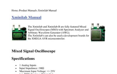
Copied from Gabriel Azziani's site - November, 2010: "Xminilab-B is a multi purpose development kit using the new XMEGA microcontrollers. It is targeted for anyone who wants to start learning AVR micros. "The Xminilab-B is also a fully featured Mixed Signal Oscilloscope and Spectrum Analyzer with an Arbitrary Function Generator. "General Specifications:
"Mixed Signal Oscilloscope Specifications:
"Arbitrary Waveform Generator Specifications:
There's an HTML manual on Gabriel's site (click here). From that, we created a .pdf version for our own reference. You can download that by clicking here (included with Gabriel's permission).
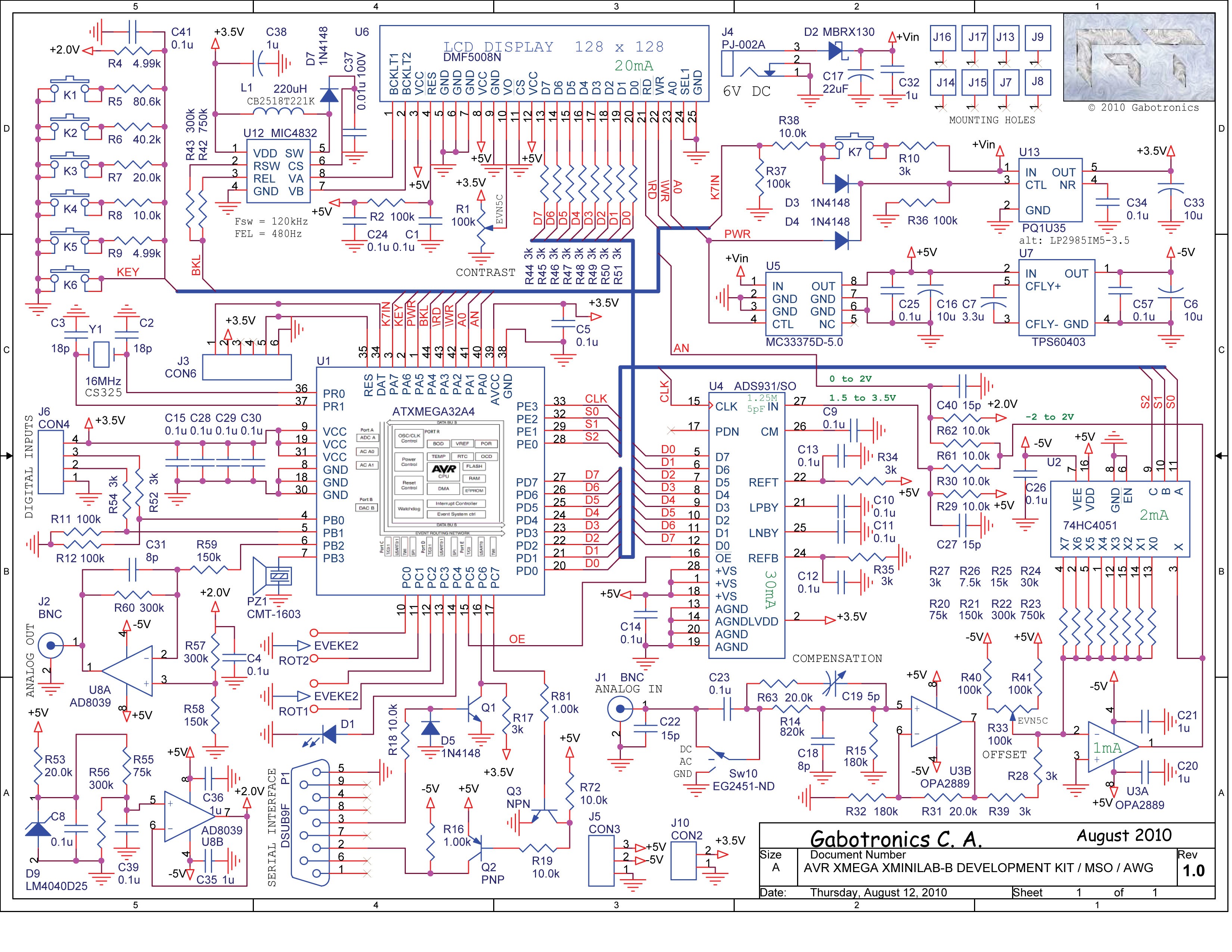
Here is the schematic drawing of the XminiLab-B circuitry:
You can download a .pdf version of the schematics by clicking here. |
||||||||||||||||||||||||||||||||||||||||||||||||||||||||||||||||||||||||||||||||||||||||||||||||||||||||||||||||||||||||||||||||||||||||||||||||||||||||||||||||||||||||||||
Modifications |
||||||||||||||||||||||||||||||||||||||||||||||||||||||||||||||||||||||||||||||||||||||||||||||||||||||||||||||||||||||||||||||||||||||||||||||||||||||||||||||||||||||||||||
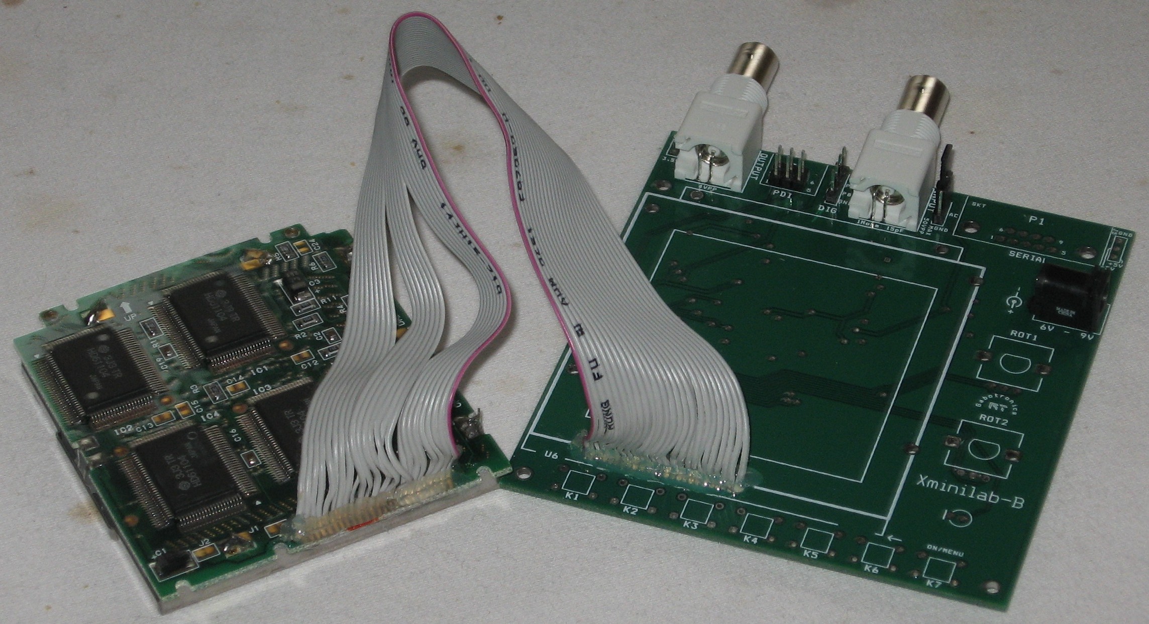
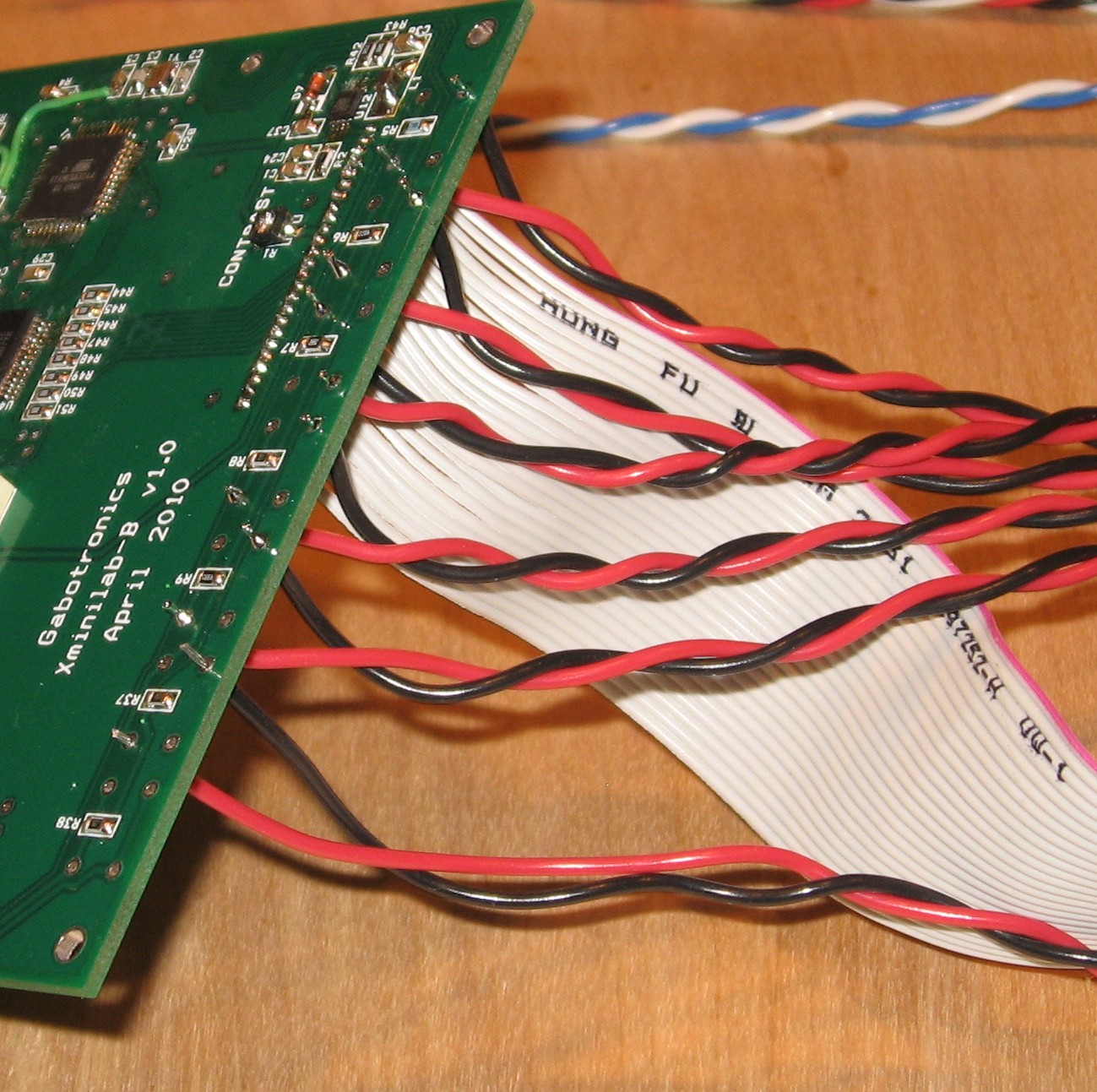
1. Ribbon Cable / ControlsIt bears noting that the guts for the thing come completely assembled from Gabriel. But we asked him to do a couple things for us special, which he generously did:
As it turns out, Gabriel soldered in the power jack and the input and output jacks but we'll work around them. Easy as cake. Piece of pie.
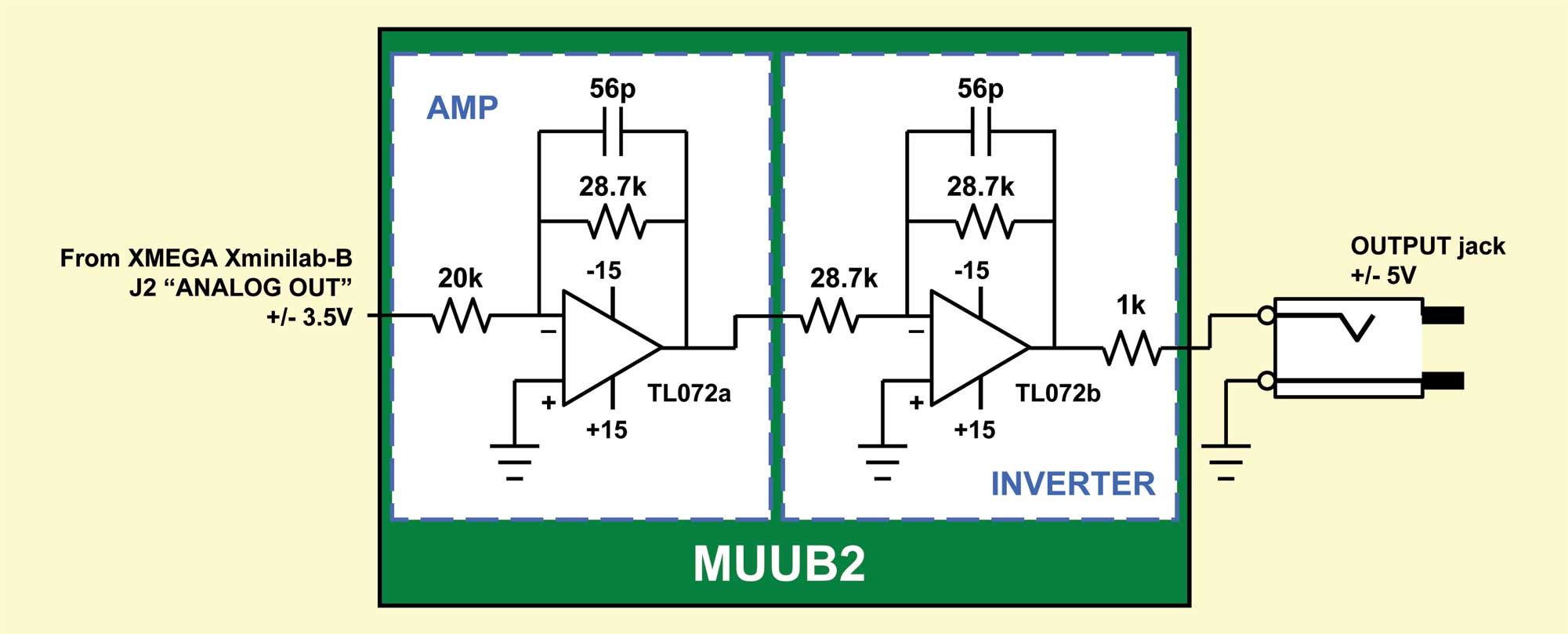
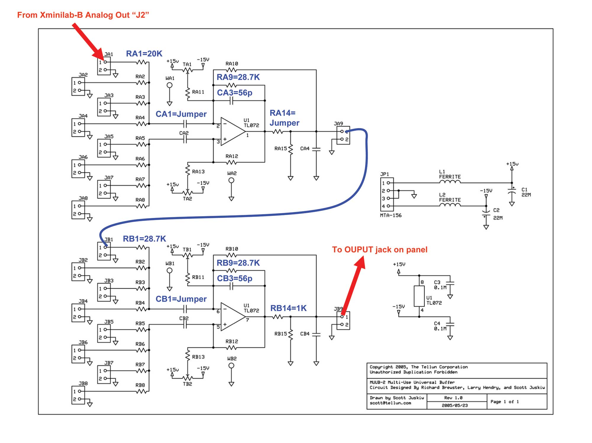
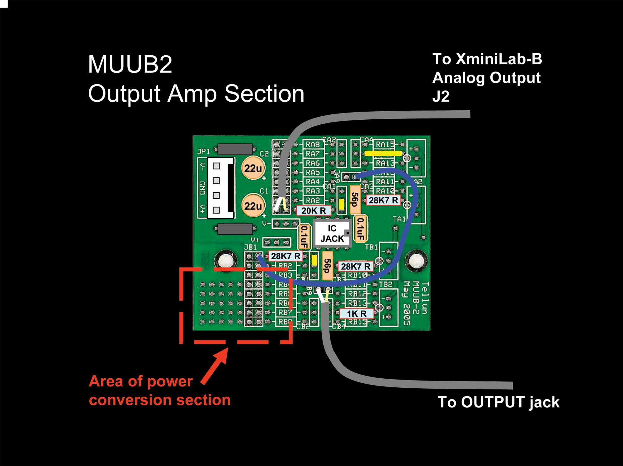
Then we contemplated a couple additional modifications - like raising the output signal from +/- 3.5V to a more standard +/- 5V (we think this is what we want) and making it so we can use our 15V power supply for power. 2. Output AmplifierWe turned to Dave Brown for assistance with an amplifier circuit we could implement on a MUUB2. We knew enough to suggested a 2 op amp approach - one op amp providing the amplification, the other inverting the signal back to the original phase (not that it really matters). Dave pointed out we could use a single non-inverting op amp, but said our approach would work too and he worked out the values of the resistors and capacitors for us:
We worked out this circuit on the MUUB2 schematic diagram:
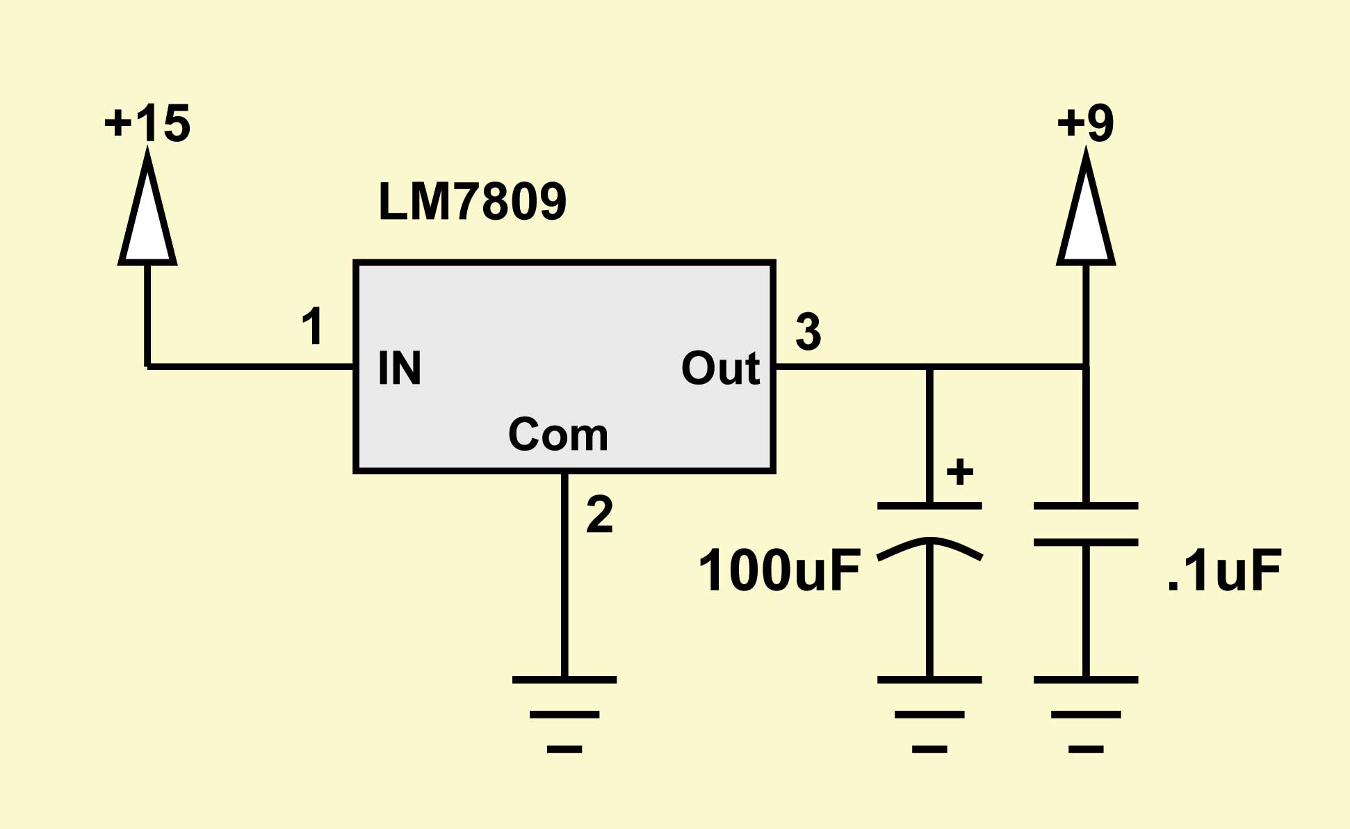
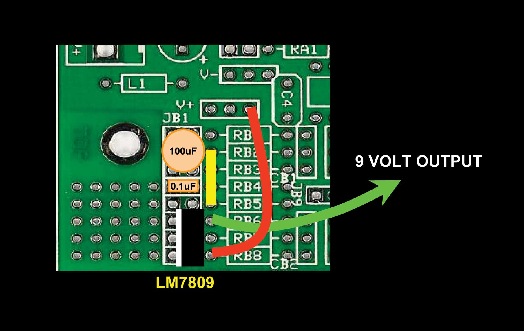
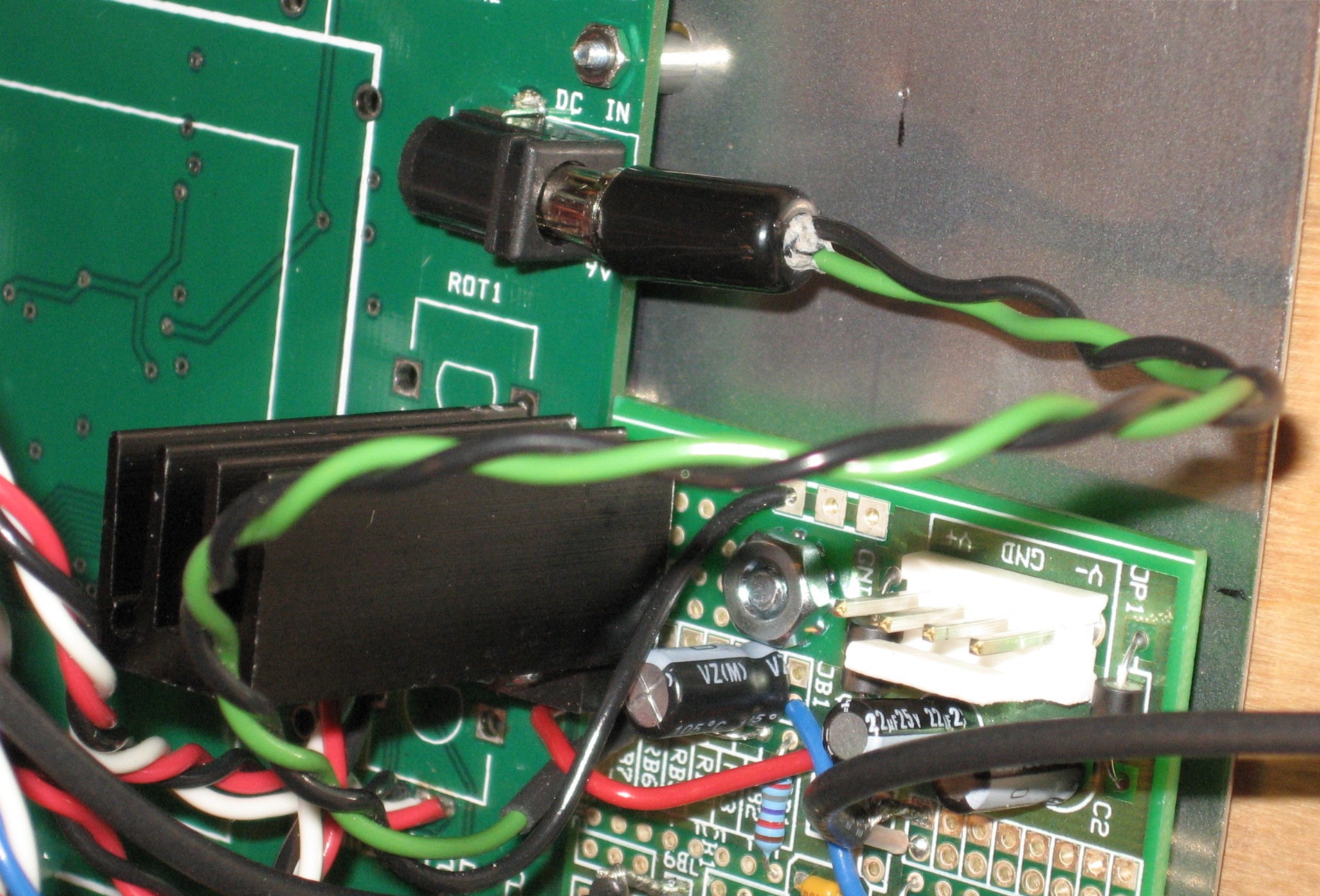
3. Power SupplyThe minilabB needs 6V to 9V / 120mA power so we needed to create a step-down using a voltage regulator. We looked back at the TL867 because we remembered Scott Juskiw implementing a +5V power supply on the little breadboard section of a MUUB4. So if we use Scott's diagram as an example, here's a schematic for how the regulator would be installed on our MUUB2:
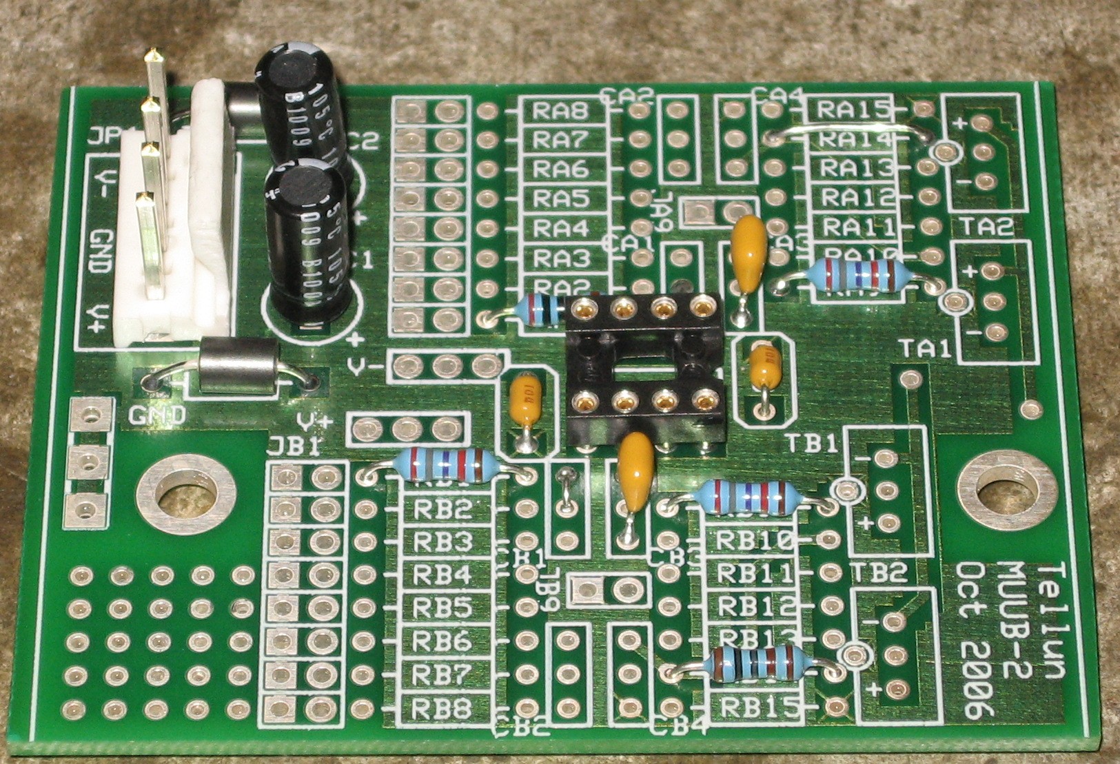
Having reviewed the minilab's schematics, Scott Juskiw suggested using a 100uF electrolytic cap (he said we could even use a 220uF cap) and a .1uF ceramic. Per Gabriel's advice, we're going to include a heat-sink for the LM7809. |
||||||||||||||||||||||||||||||||||||||||||||||||||||||||||||||||||||||||||||||||||||||||||||||||||||||||||||||||||||||||||||||||||||||||||||||||||||||||||||||||||||||||||||
Parts |
||||||||||||||||||||||||||||||||||||||||||||||||||||||||||||||||||||||||||||||||||||||||||||||||||||||||||||||||||||||||||||||||||||||||||||||||||||||||||||||||||||||||||||
|
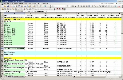
Will and I have developed a parts-list / bill-of-materials in the form of an XL spreadsheet (as usual). The list is really for the various panel-mounted controls and connection things. Please note that these are the parts we got to prototype our implementation. As we progress with our build, we'll update the BOM. But the momentary switches are the same as were used by Richard Kim and David Ingbretsen, the NKK switch is the same as was used by RK, the encoders...
Click here to download our XL spreadsheet Parts List |
||||||||||||||||||||||||||||||||||||||||||||||||||||||||||||||||||||||||||||||||||||||||||||||||||||||||||||||||||||||||||||||||||||||||||||||||||||||||||||||||||||||||||||
Miscellaneous Parts |
||||||||||||||||||||||||||||||||||||||||||||||||||||||||||||||||||||||||||||||||||||||||||||||||||||||||||||||||||||||||||||||||||||||||||||||||||||||||||||||||||||||||||||
|
Power Plug - 2.1mm, 5.5mm OD from Radio Shack |
||||||||||||||||||||||||||||||||||||||||||||||||||||||||||||||||||||||||||||||||||||||||||||||||||||||||||||||||||||||||||||||||||||||||||||||||||||||||||||||||||||||||||||
PCB Mounting Bracket |
||||||||||||||||||||||||||||||||||||||||||||||||||||||||||||||||||||||||||||||||||||||||||||||||||||||||||||||||||||||||||||||||||||||||||||||||||||||||||||||||||||||||||||
|
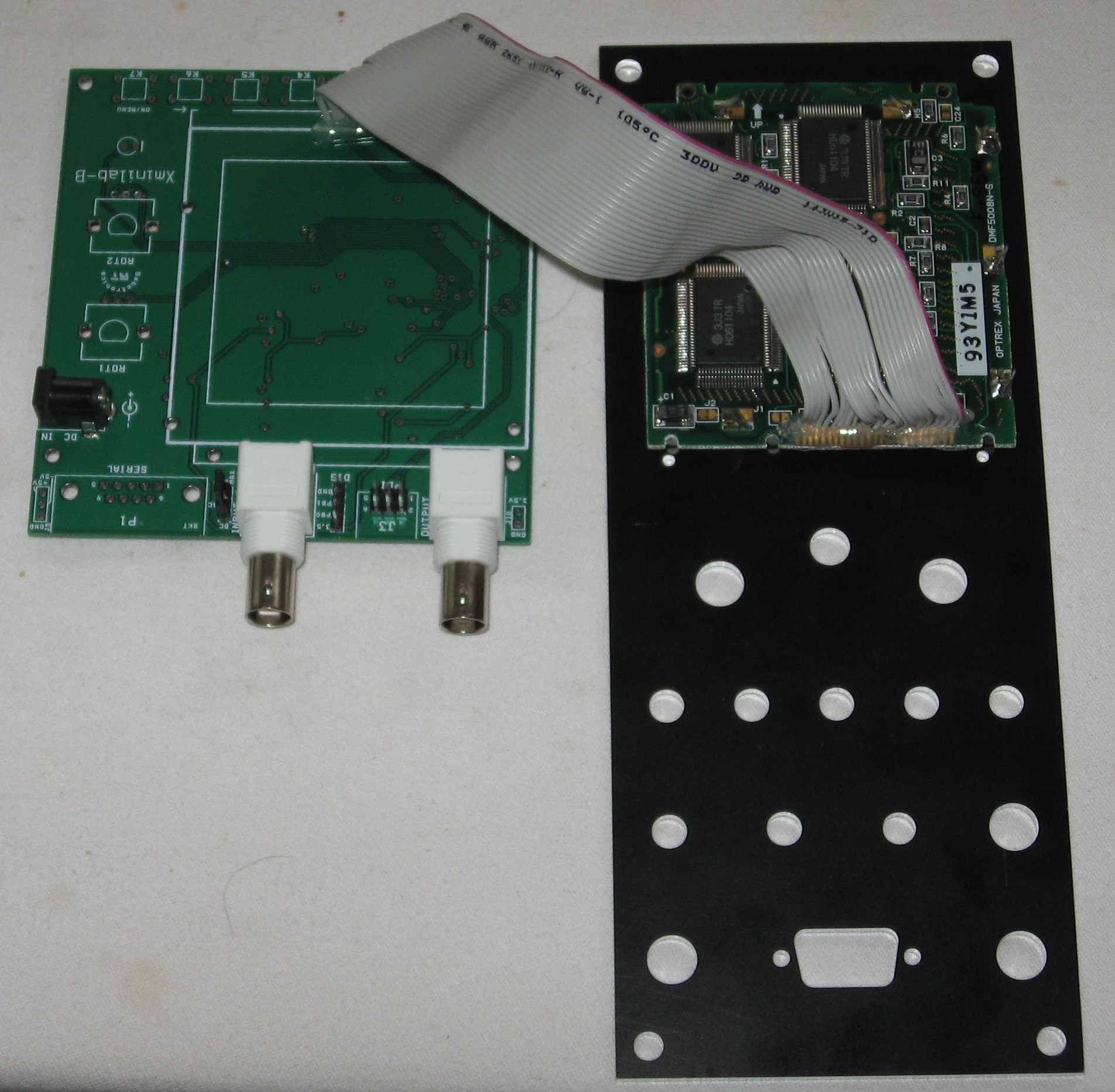
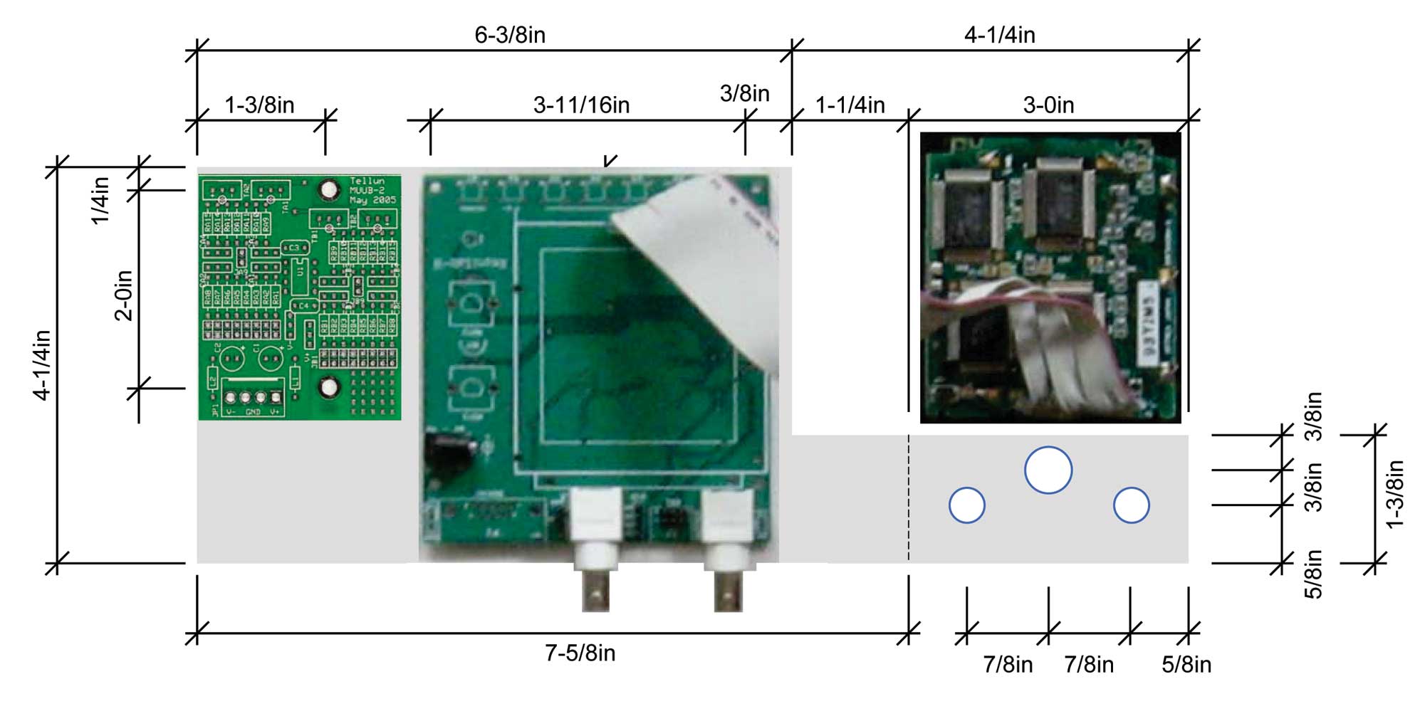
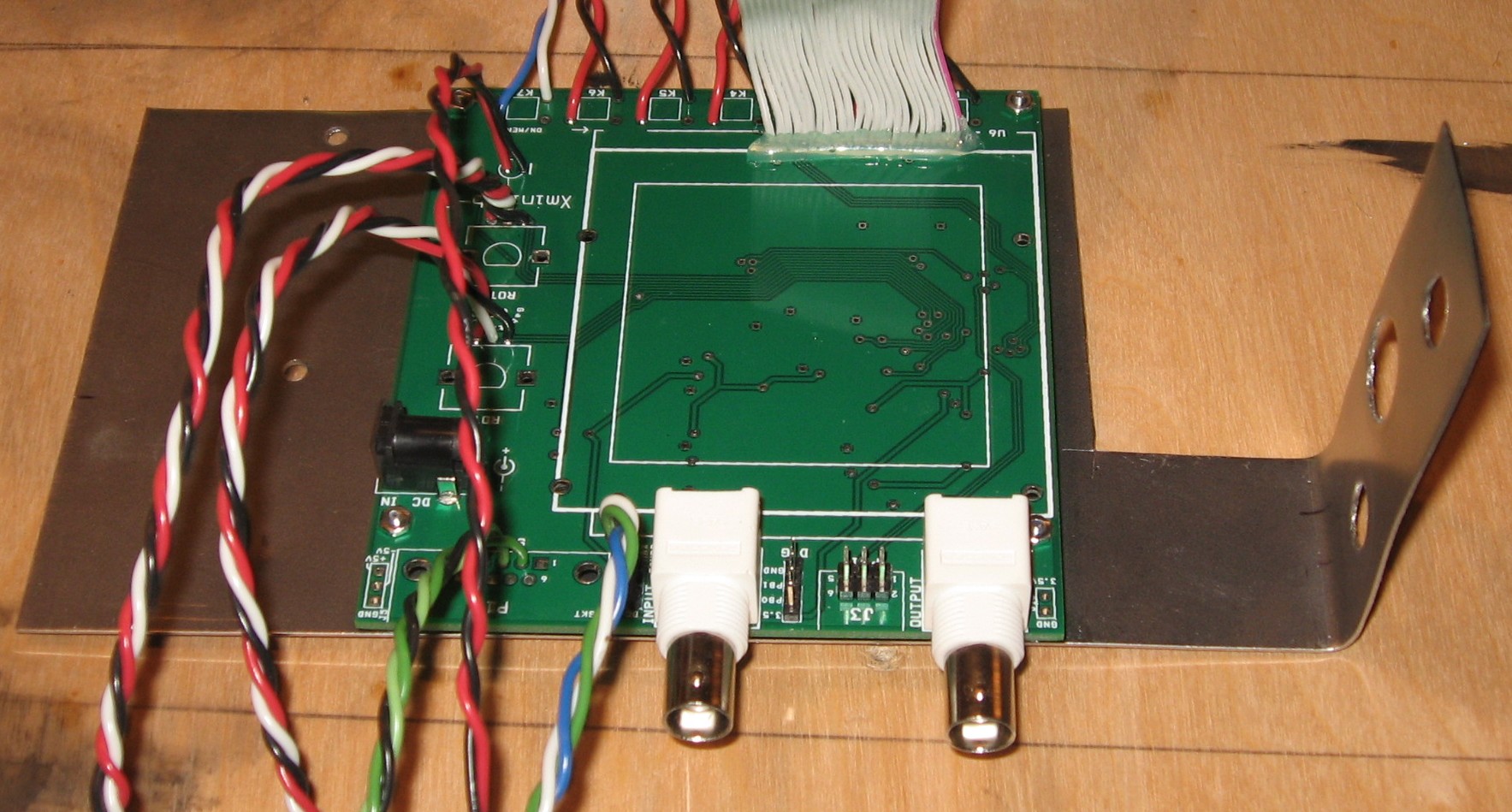
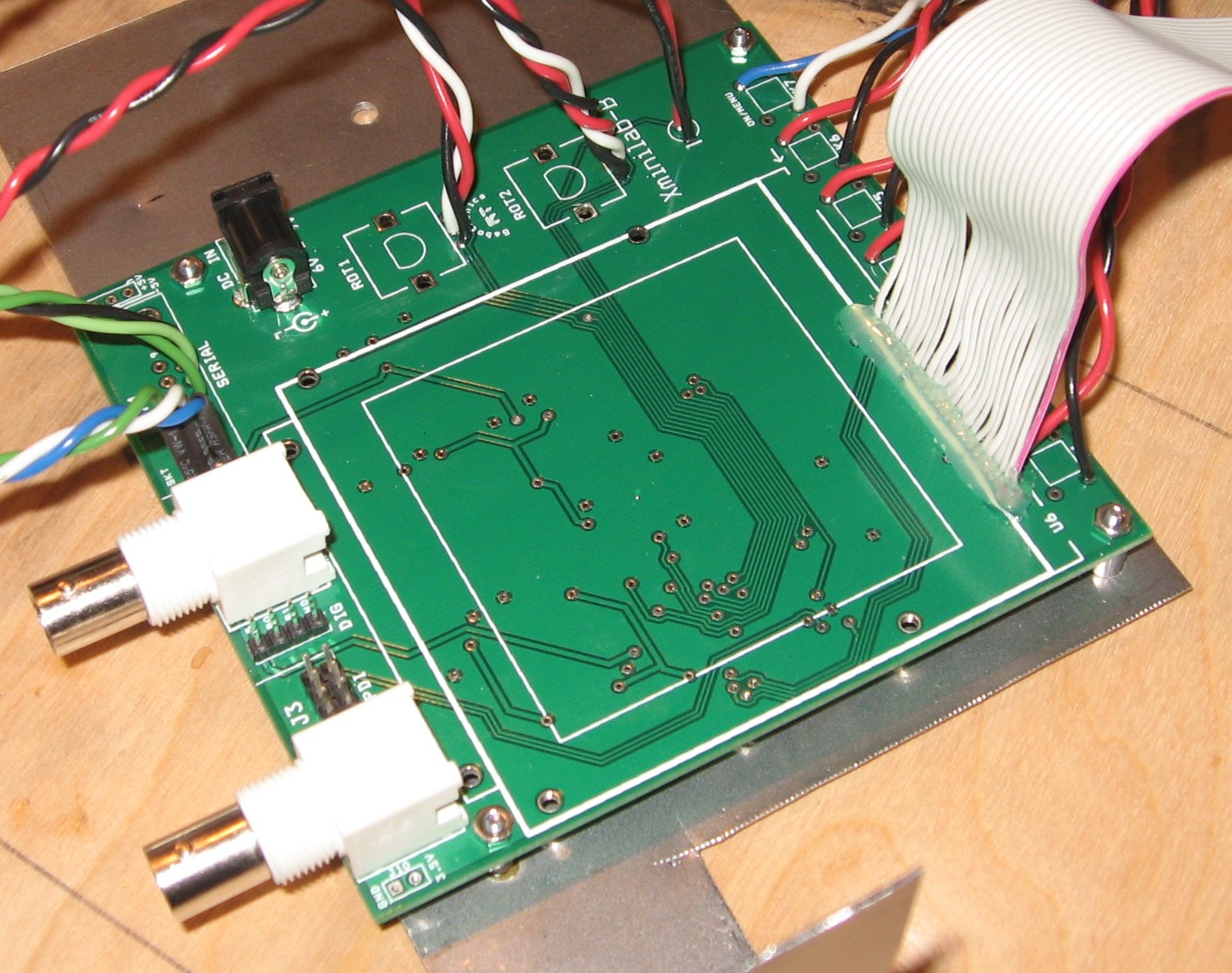
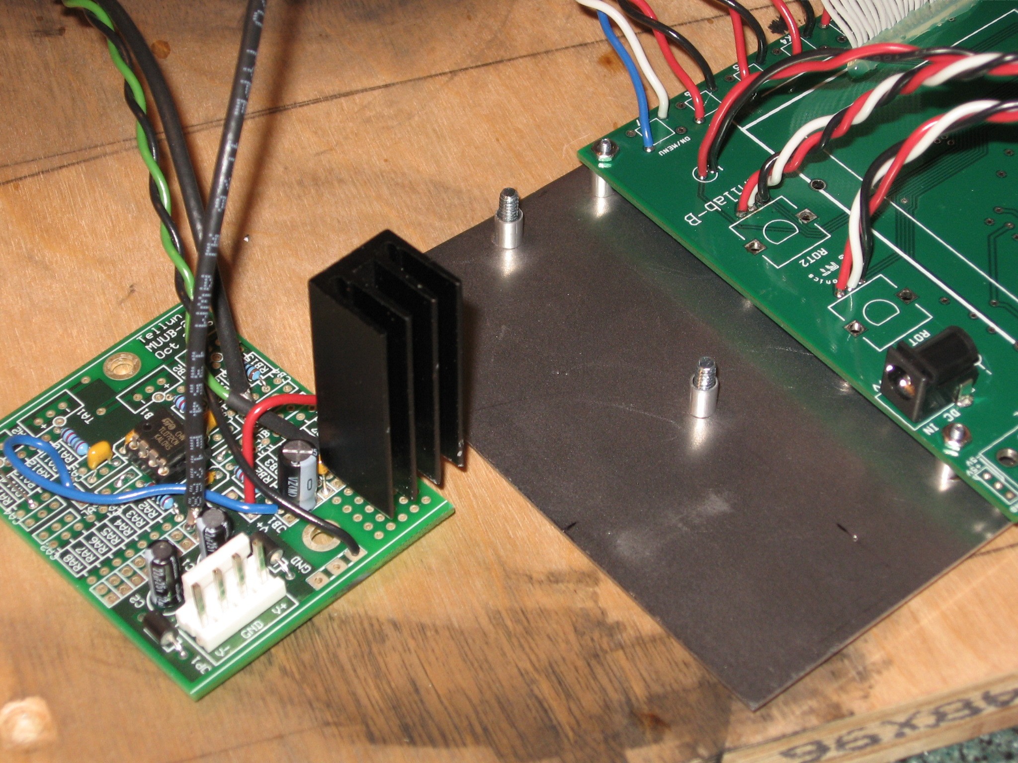
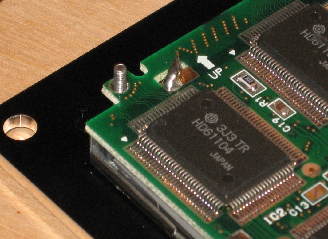
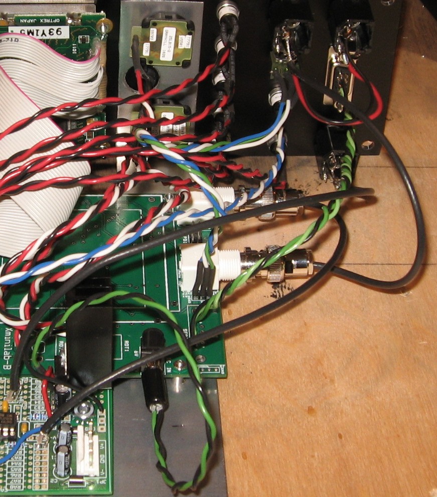
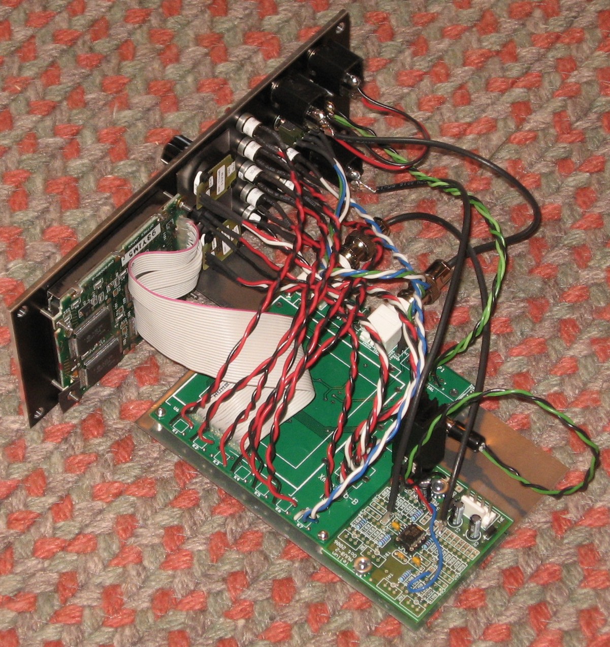
This took some thinking as well. We're going to orient the PCBs like this behind the panel.
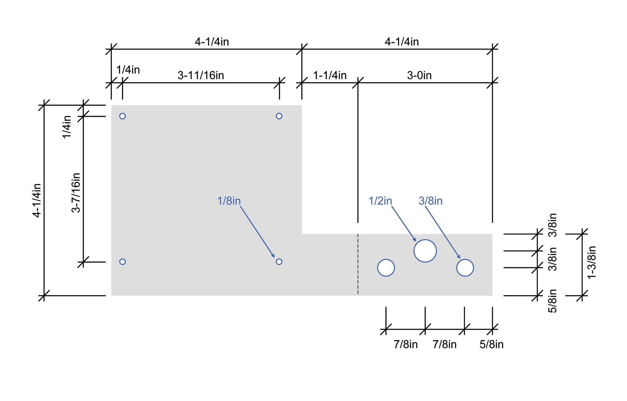
So here's our first stab at the mounting bracket. It doesn't have the mounting holes for the MUUB2 we anticipate using to install the 9V power regulator and amp to raise the output to +/-5V. But this bracket design may come in handy for you if you don't want to include those things.
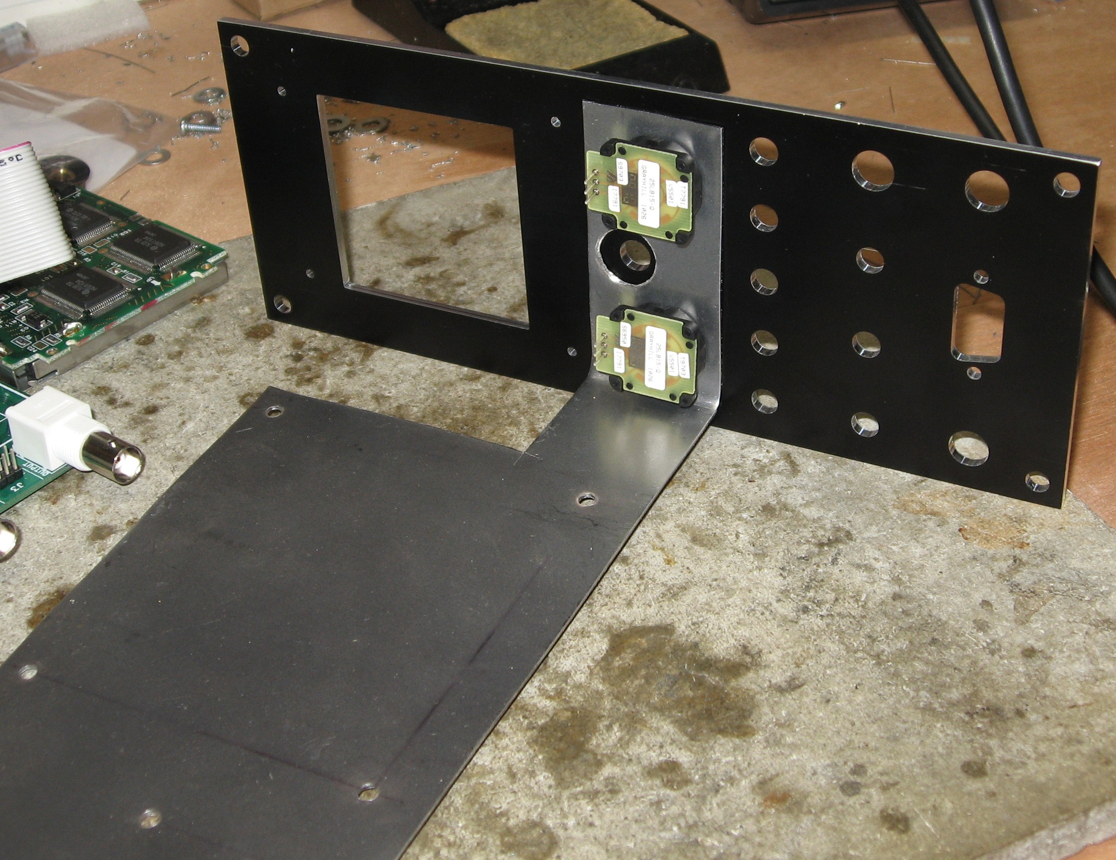
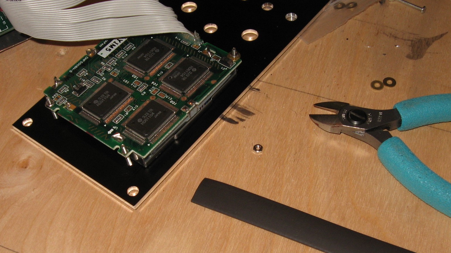
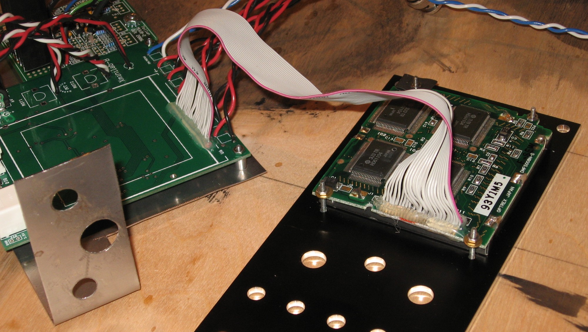
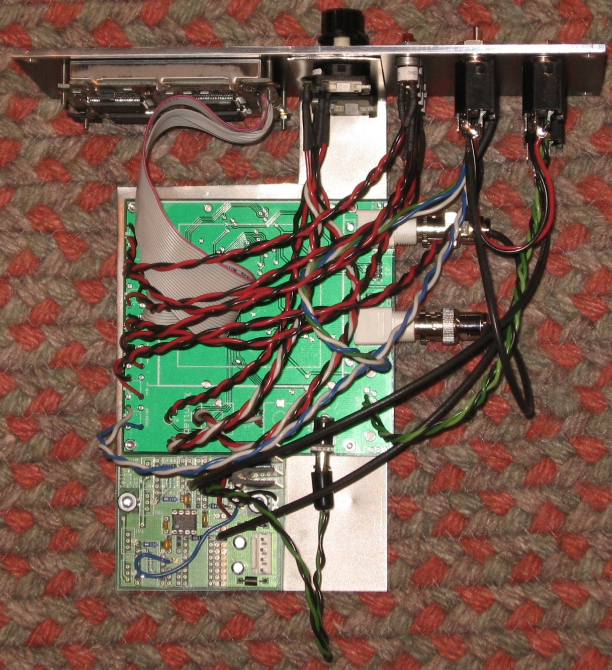
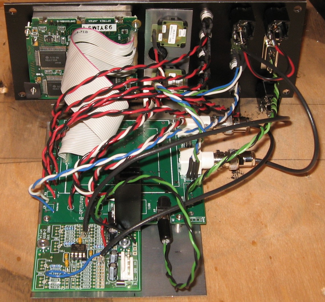
Now - we included the MUUB2 in our build. Here's how the PCBs laid out:
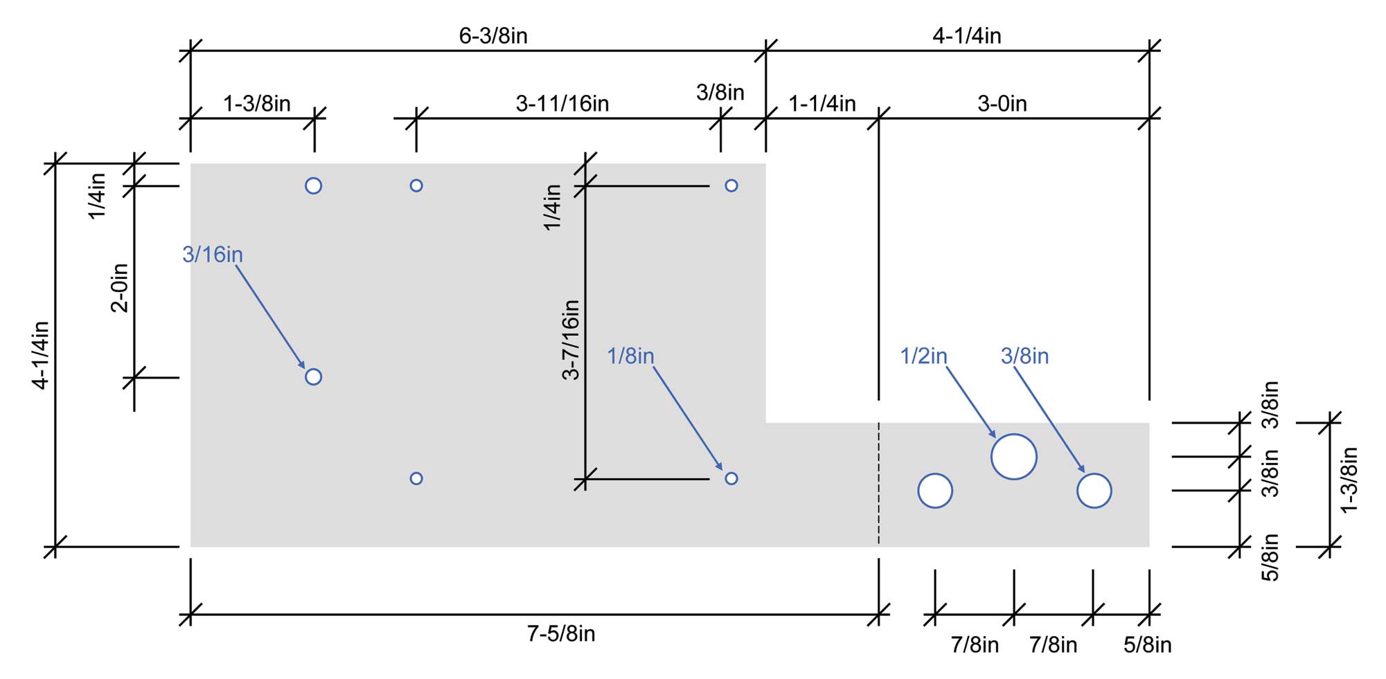
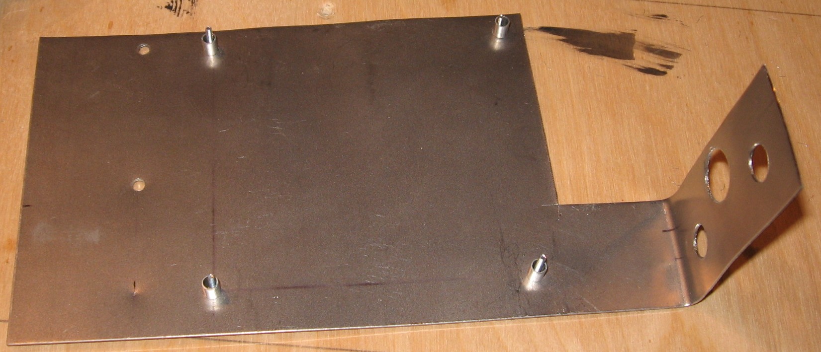
And here's our final bracket design:
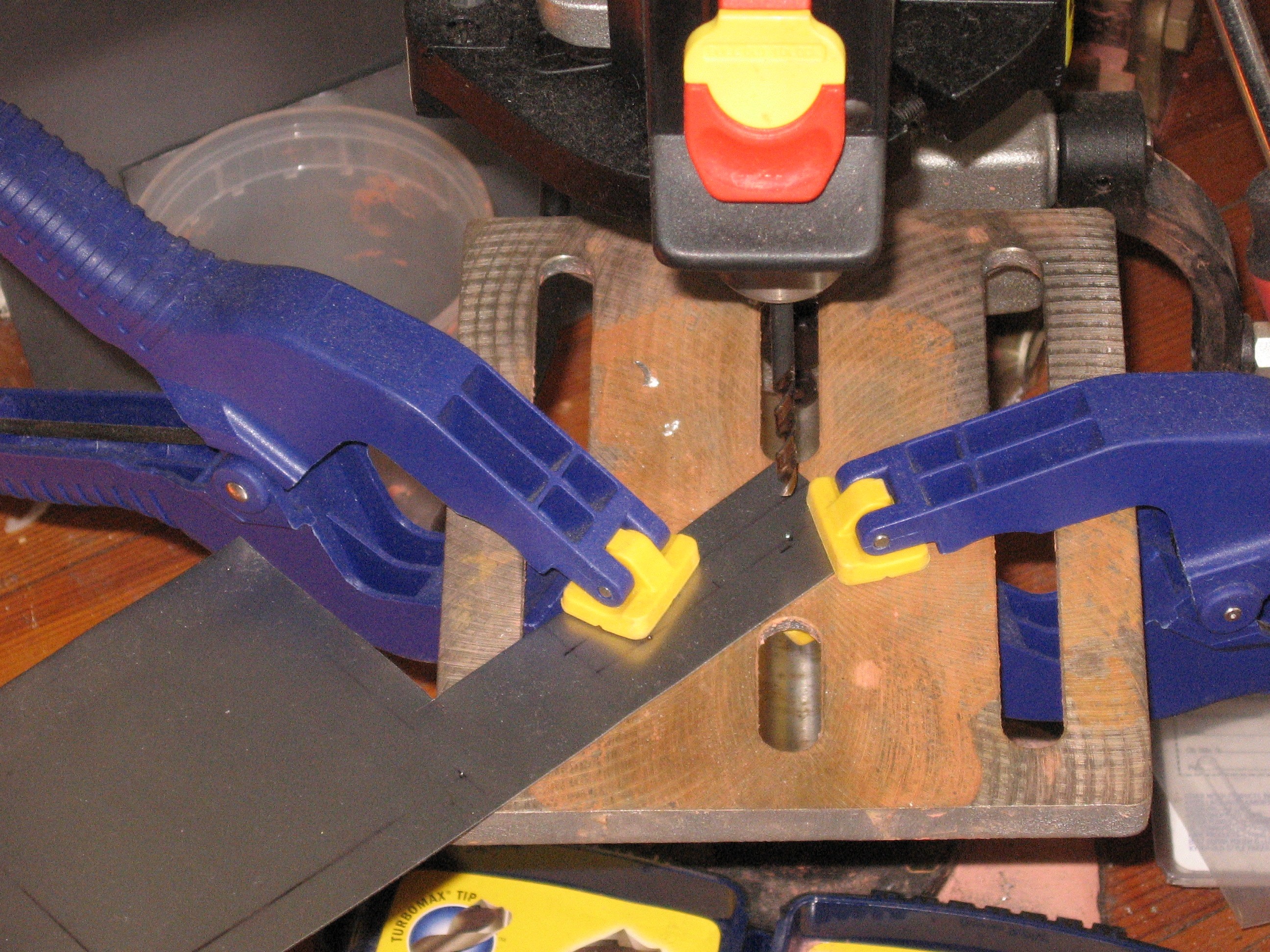
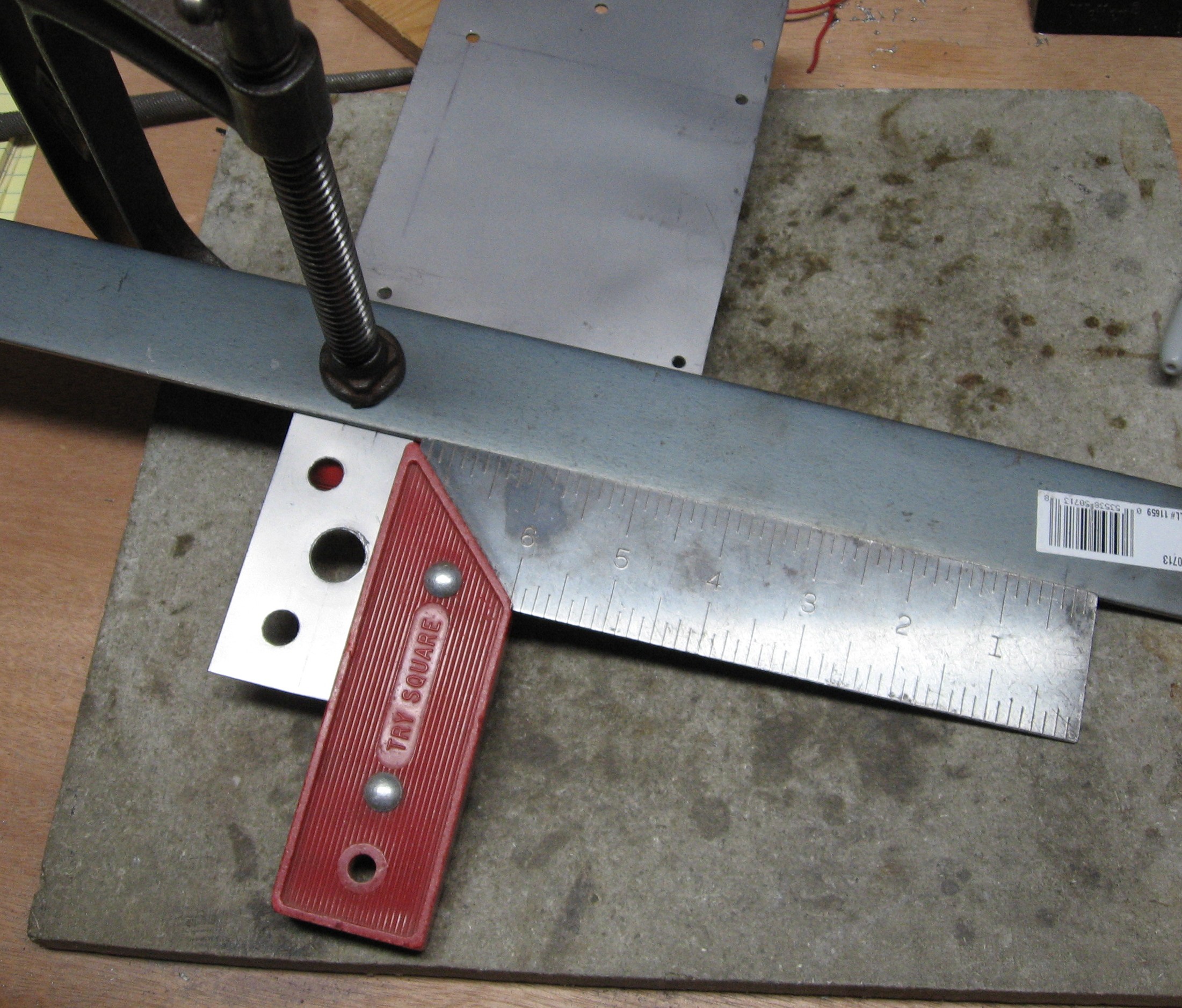
So we cut the bracket out of sheet steel per our design, and went about drilling the holes:
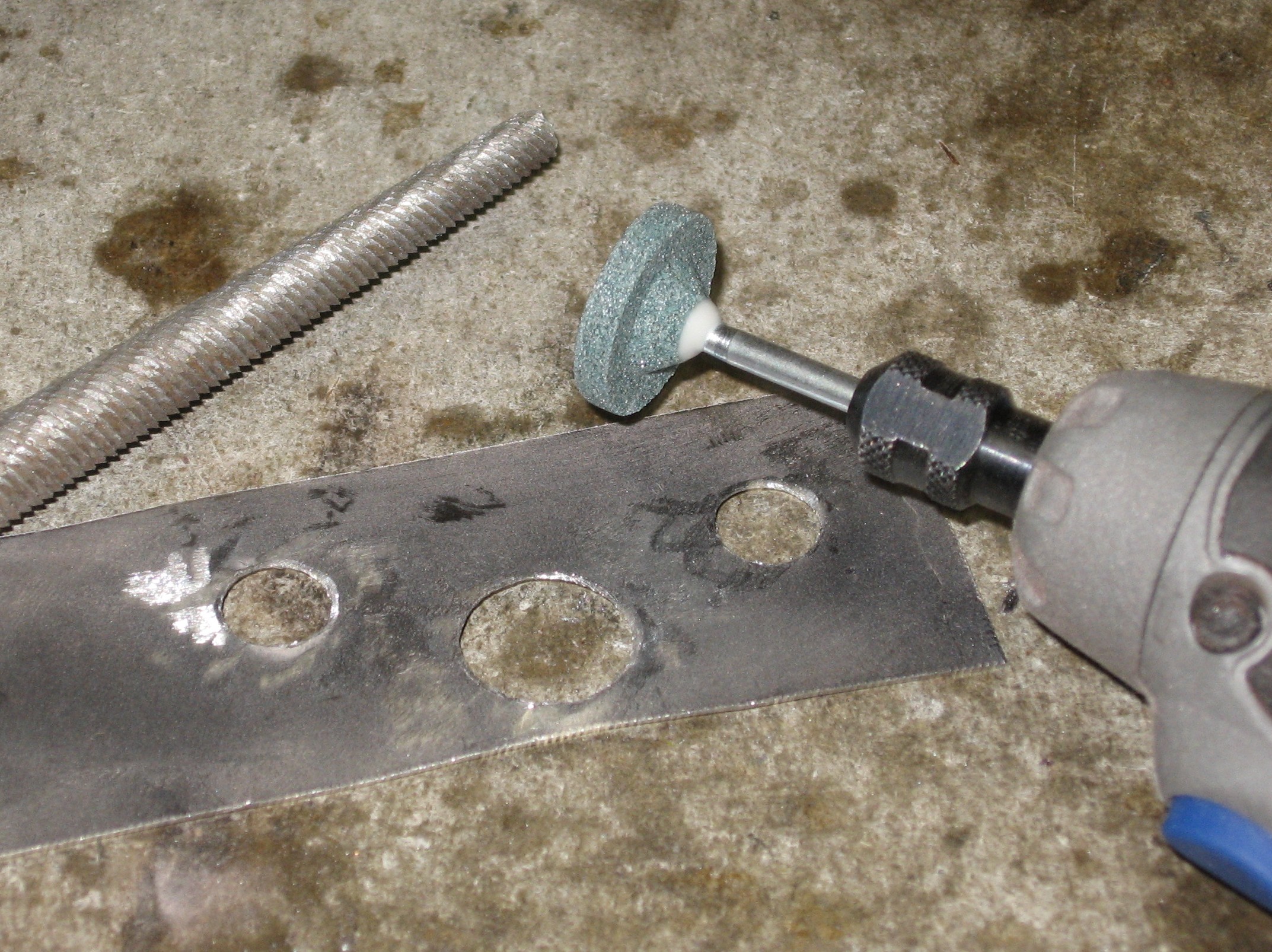
we ground away the rough back-side of the holes with a dremmel tool:
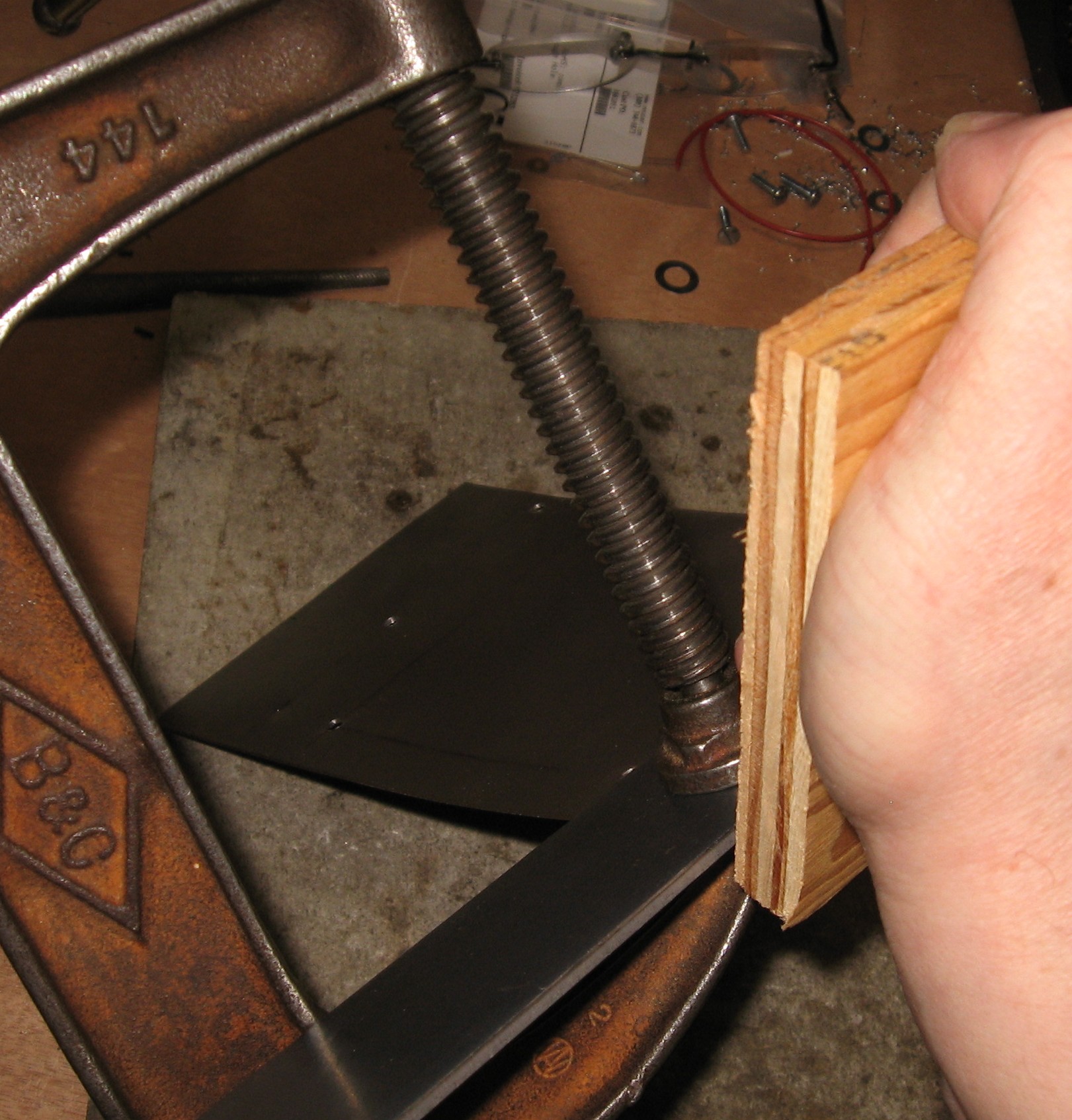
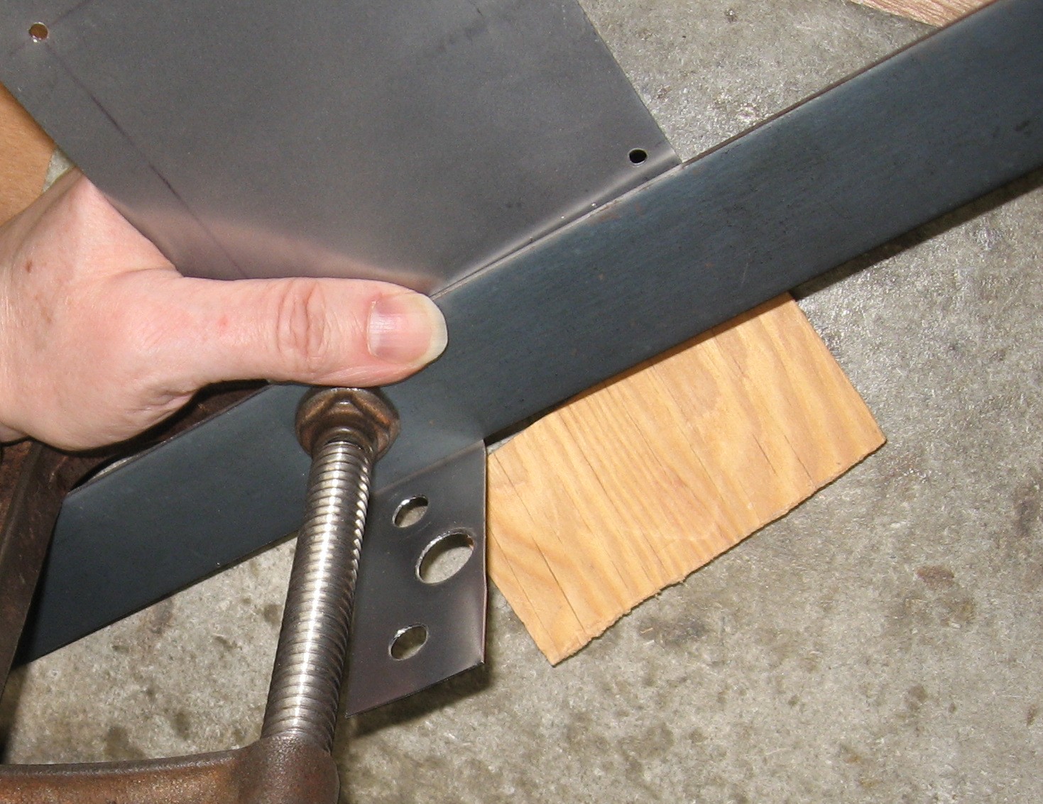
we bent the bracket using a piece of steel bar and C-clamp as a crude break. We really should buy a nice one - but - <shrug>:
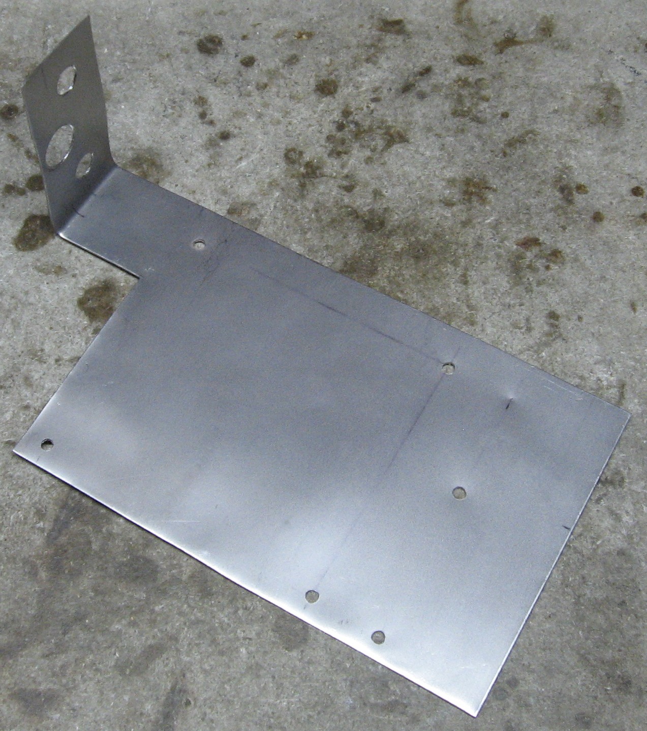
finished bracket:
|
||||||||||||||||||||||||||||||||||||||||||||||||||||||||||||||||||||||||||||||||||||||||||||||||||||||||||||||||||||||||||||||||||||||||||||||||||||||||||||||||||||||||||||
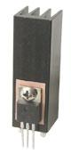
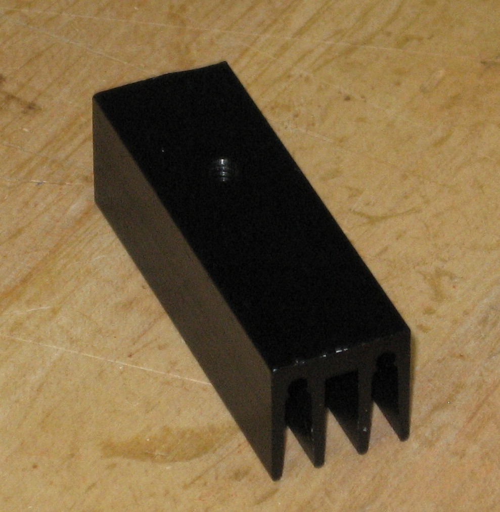
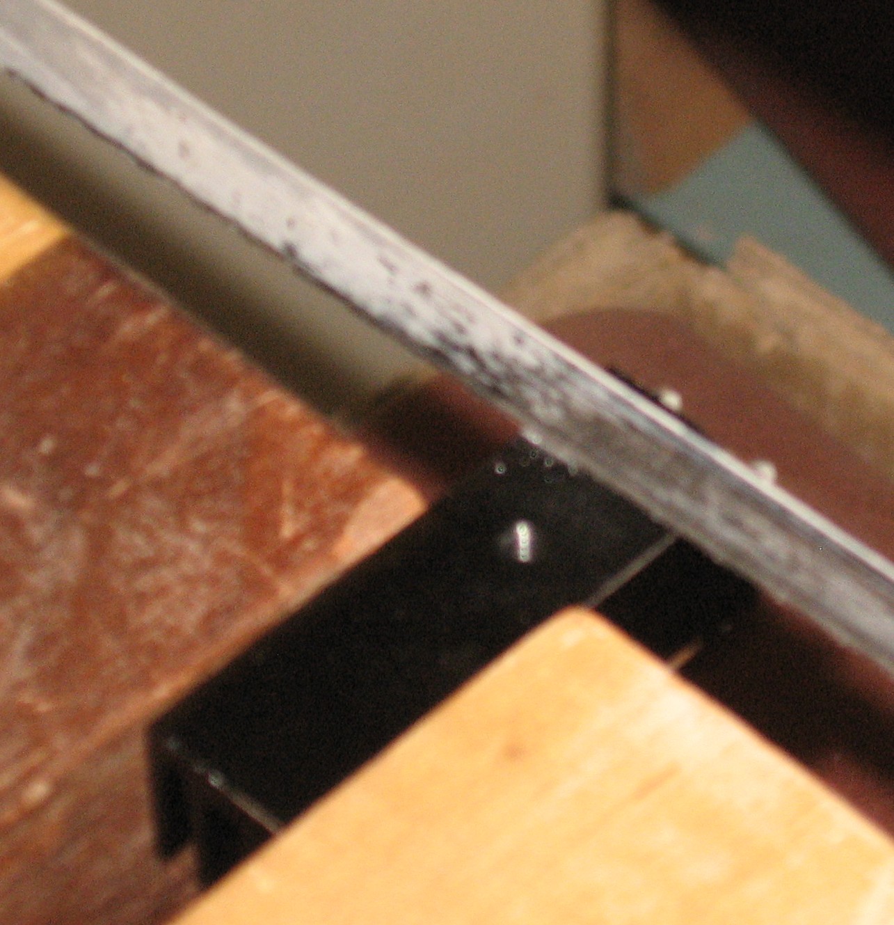
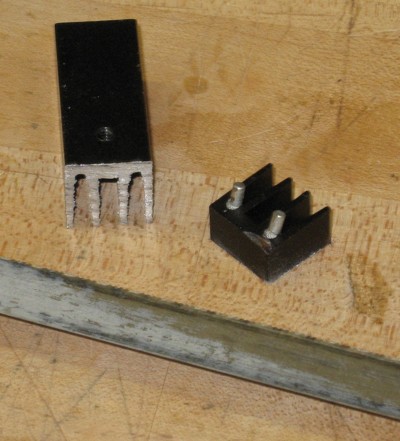
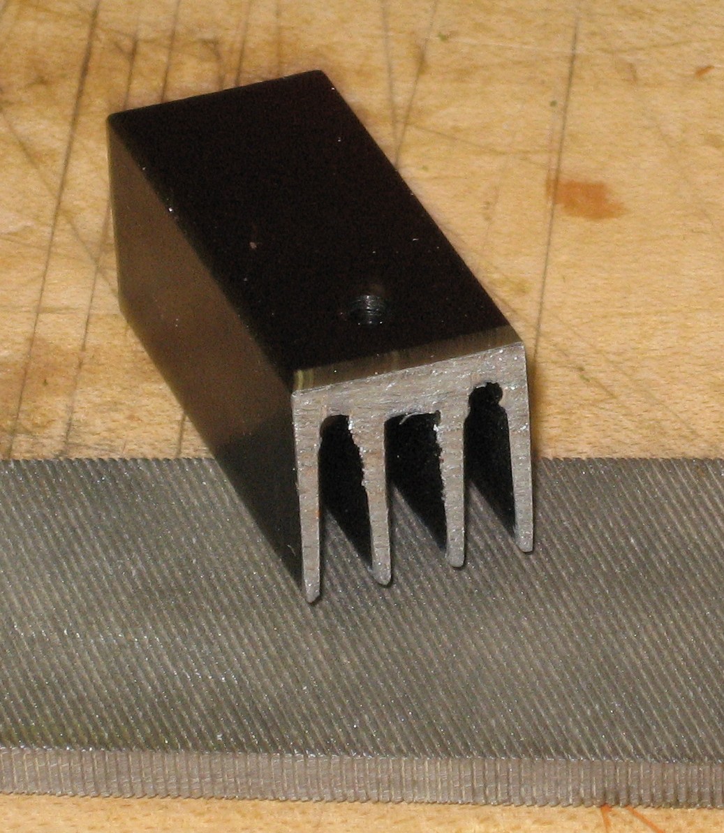
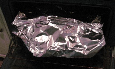
Heat Sink ModificationIf you're building this thing, you may not need to do this at all, but the heat sink we ordered for the LM7809 (it's listed in our BOM - the Aavid Thermalloy, Mouser# 532-581202B25G) is a size we liked. It's got a 6-32 threaded hole with which to bolt it to the LM7809. But it has mounting pins in the wrong spot for us and it's taller than we want it to be below the bolt-hole. No biggie - a hacksaw did the trick.
|
||||||||||||||||||||||||||||||||||||||||||||||||||||||||||||||||||||||||||||||||||||||||||||||||||||||||||||||||||||||||||||||||||||||||||||||||||||||||||||||||||||||||||||
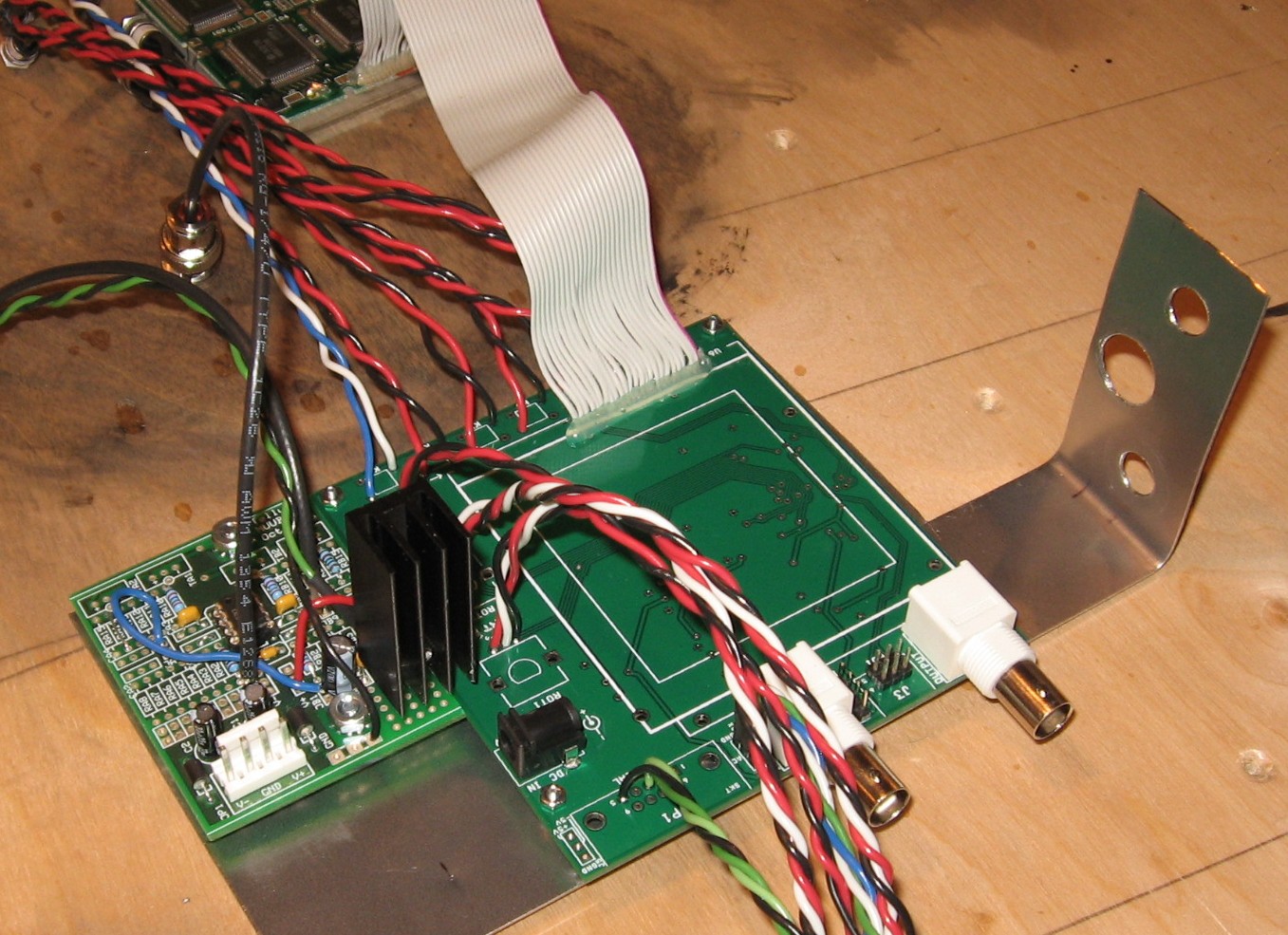
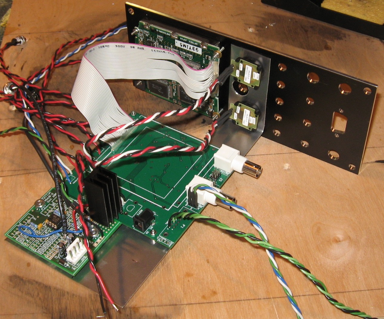
Connection WiresDuring construction, we set the PCB on the bracket with the panel so we could work out the connection wire lengths - and we made a chart for the module's connection wiring:
Wires Chart
|
||||||||||||||||||||||||||||||||||||||||||||||||||||||||||||||||||||||||||||||||||||||||||||||||||||||||||||||||||||||||||||||||||||||||||||||||||||||||||||||||||||||||||||
Panel |
||||||||||||||||||||||||||||||||||||||||||||||||||||||||||||||||||||||||||||||||||||||||||||||||||||||||||||||||||||||||||||||||||||||||||||||||||||||||||||||||||||||||||||
|
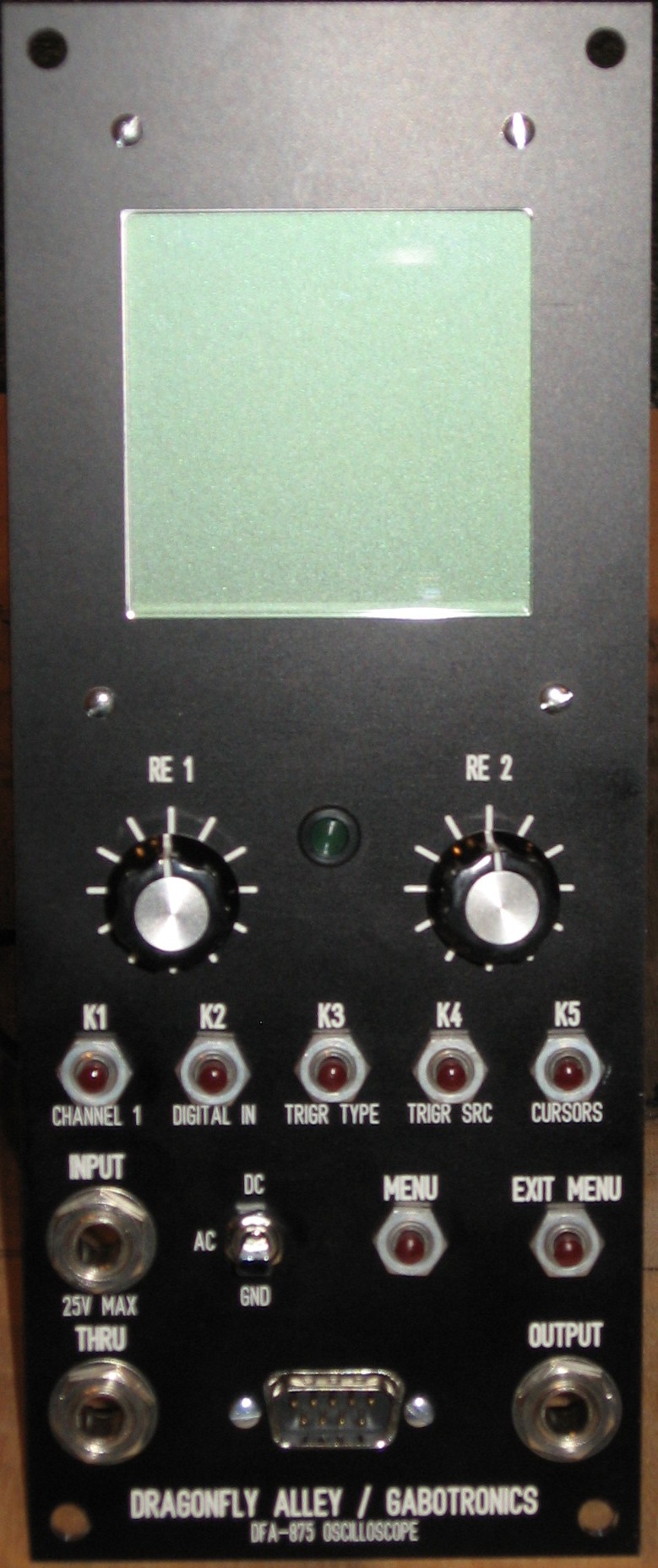
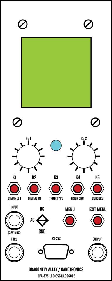
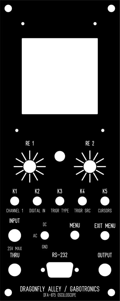
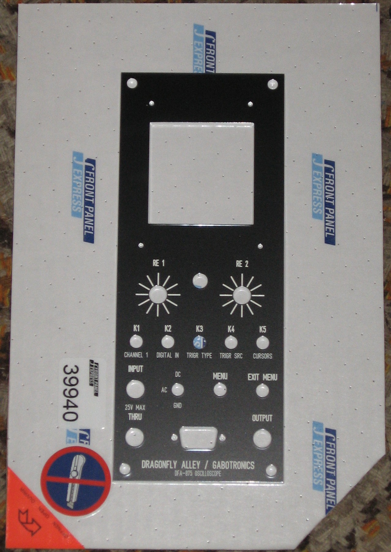
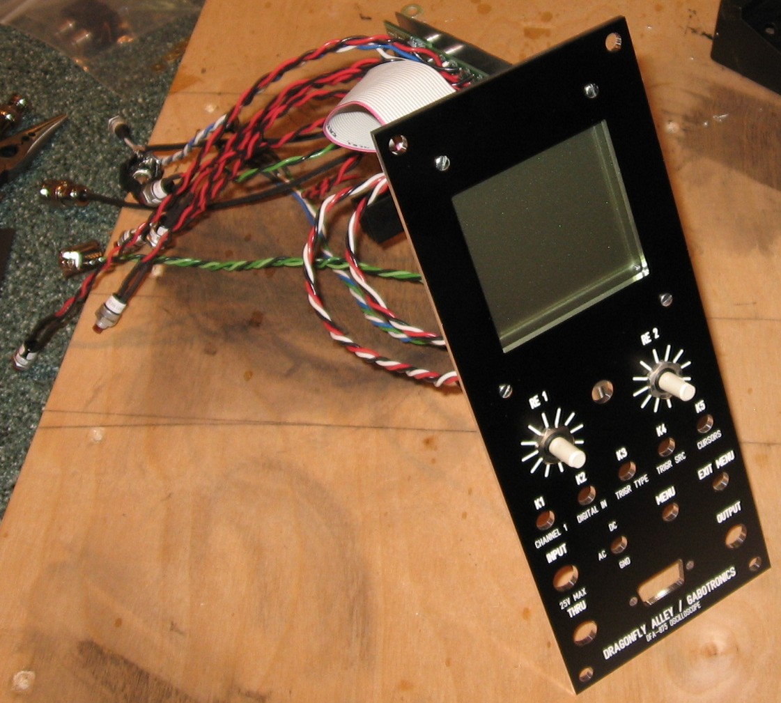
This took some thinking and was an evolutionary process. The panel design started out simpler and was based closely on David Ingbretsen's Eurorack concept. As we were stalled for several months, Richard Kim built his (using an older minilabB) so we re-examined the panel design based on his experience and lots of input from Gabriel about the newer XMEGA mililabB which is what ours is based on. Now, it bears noting that we've put "Dragonfly Alley" in a prominent place on the panel. That's for fun, not 'cause we're claiming some kind of ownership of the module's concept. We don't feel bad about doing it - the panel's just for our own use and we feel that enough of this module's design is because of our own effort, that we're not misrepresenting something by putting DFA on it in our own system. But this panel is just for us so it doesn't really matter. But if you're going to use our panel design, please do as you will with that aspect of it. Also, we're not really clear that the panel mounting holes are the right size. You might need to drill them out a tiny bit bigger depending on the size screws you're using to mount the module to the rails in your system. OK? Oh - and the scale markings around the two encoders assume a small knob - the 3/4 inch kind listed in our BOM. The normal, 1 inch MTOM standard knob overhands the scale altogether. So if you're going to use the larger knob, you'll want to adjust the size of the scale ticks.
Click here to download our FPD panel file. And here's how it came from PFE:
|
||||||||||||||||||||||||||||||||||||||||||||||||||||||||||||||||||||||||||||||||||||||||||||||||||||||||||||||||||||||||||||||||||||||||||||||||||||||||||||||||||||||||||||
ConstructionThis consisted of two parts; building the MUUB2 daughter-board and soldering in the panel connections for the XminiLab-B. The module's inner workings were already assembled by Gabriel so that wasn't at all part of the build, of course. |
||||||||||||||||||||||||||||||||||||||||||||||||||||||||||||||||||||||||||||||||||||||||||||||||||||||||||||||||||||||||||||||||||||||||||||||||||||||||||||||||||||||||||||
MUUB2 daughterboard |
||||||||||||||||||||||||||||||||||||||||||||||||||||||||||||||||||||||||||||||||||||||||||||||||||||||||||||||||||||||||||||||||||||||||||||||||||||||||||||||||||||||||||||
|
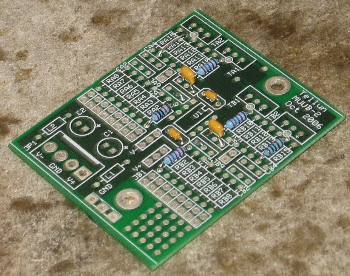
February, 2011 - Construction Phase 1All the stuff in Phase 1 gets soldered using "Organic" Solder. At every break in the action, we wash the board off to get rid of the flux. |
||||||||||||||||||||||||||||||||||||||||||||||||||||||||||||||||||||||||||||||||||||||||||||||||||||||||||||||||||||||||||||||||||||||||||||||||||||||||||||||||||||||||||||
|
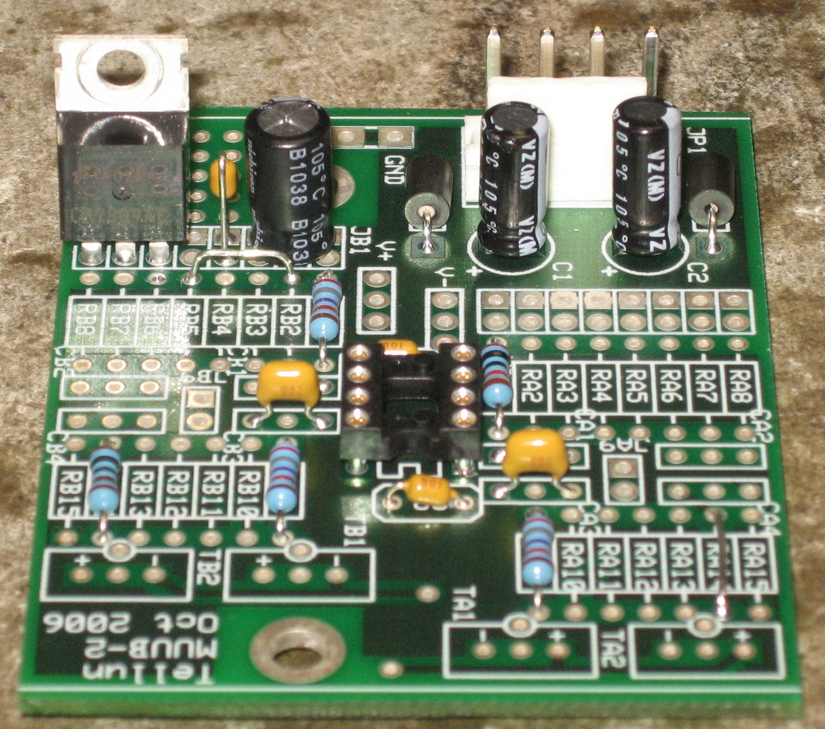
MUUB2 Output Amp
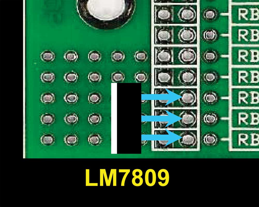
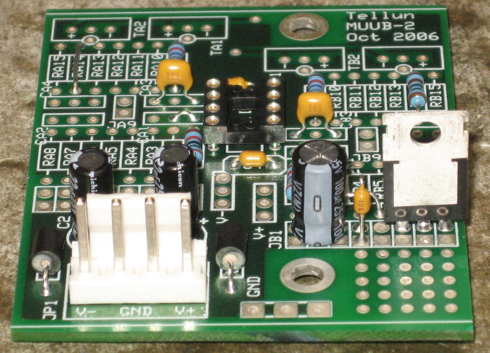
Power Converter
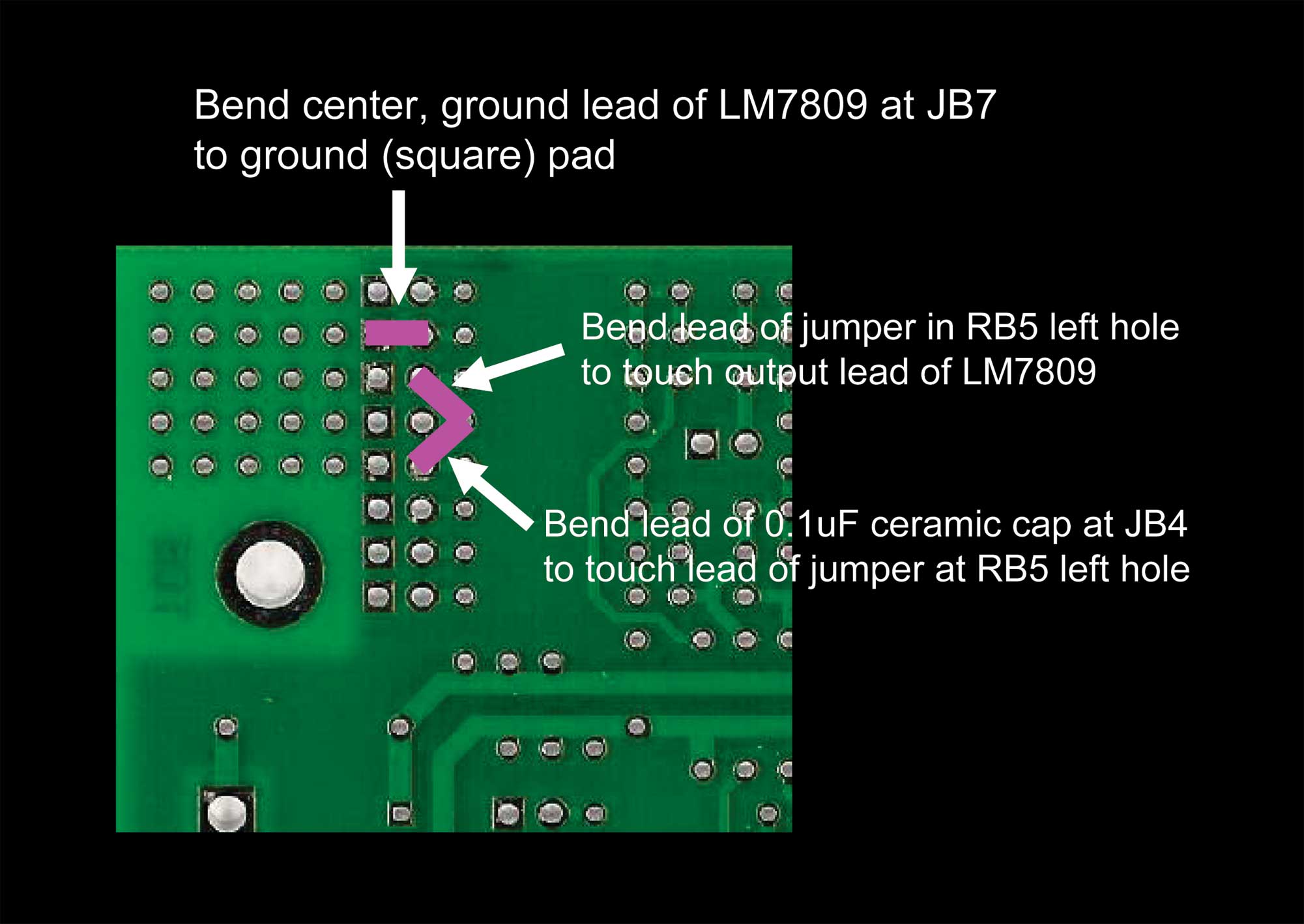
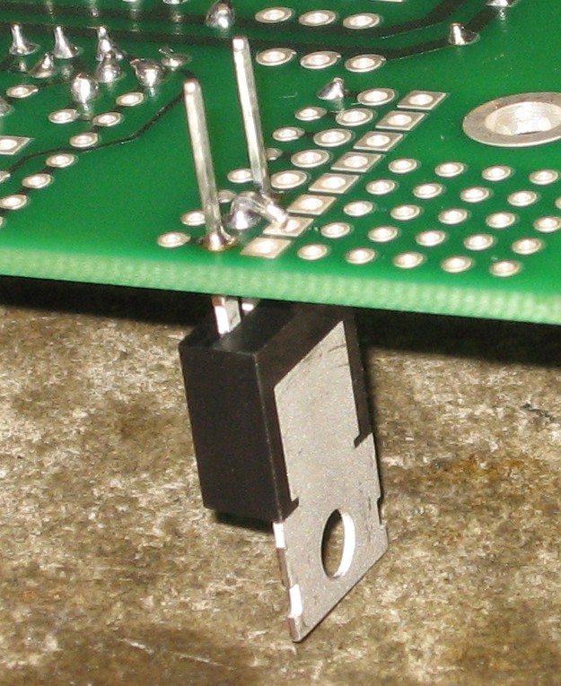
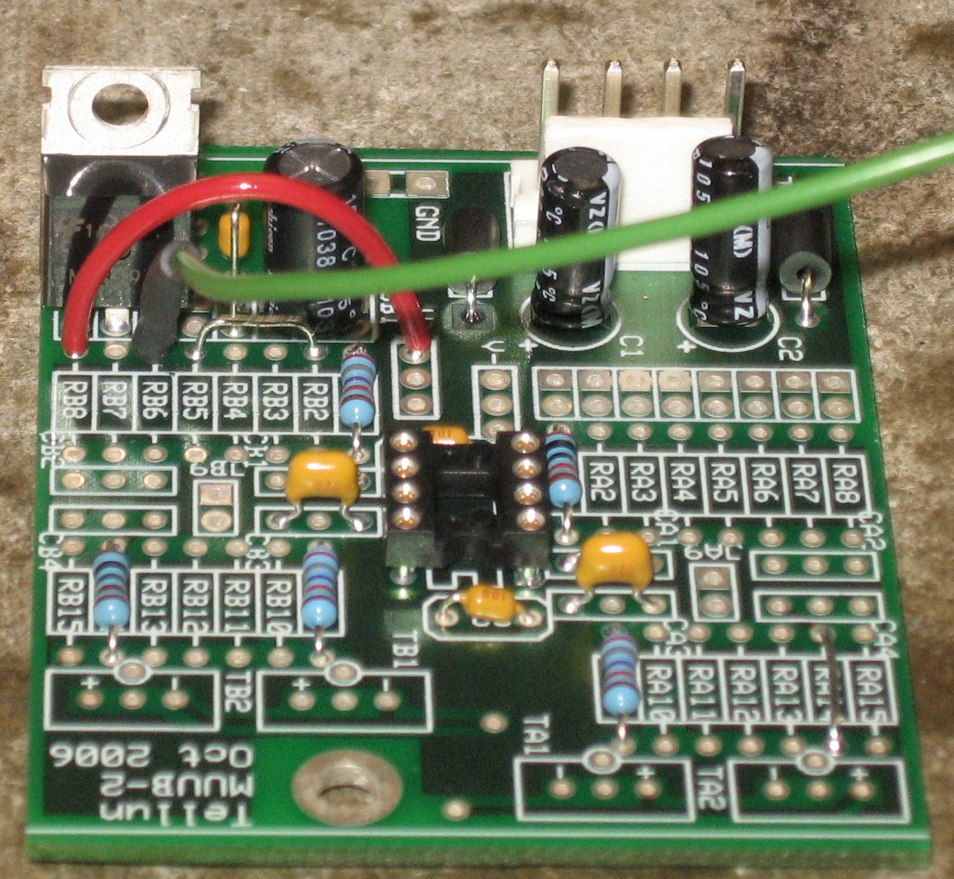
The center, ground wire of LM7809 bent to ground (square) pad:
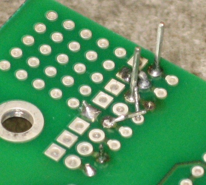
jumper lead at RB5 bent to LM7809 output lead, ceramic cap lead at JB4 bent to jumper at RB5:
|
||||||||||||||||||||||||||||||||||||||||||||||||||||||||||||||||||||||||||||||||||||||||||||||||||||||||||||||||||||||||||||||||||||||||||||||||||||||||||||||||||||||||||||
Construction Phase 2All the stuff in Phase 2 gets soldered using "No-Clean" Solder and the PCB doesn't get washed off from here on. |
||||||||||||||||||||||||||||||||||||||||||||||||||||||||||||||||||||||||||||||||||||||||||||||||||||||||||||||||||||||||||||||||||||||||||||||||||||||||||||||||||||||||||||
|
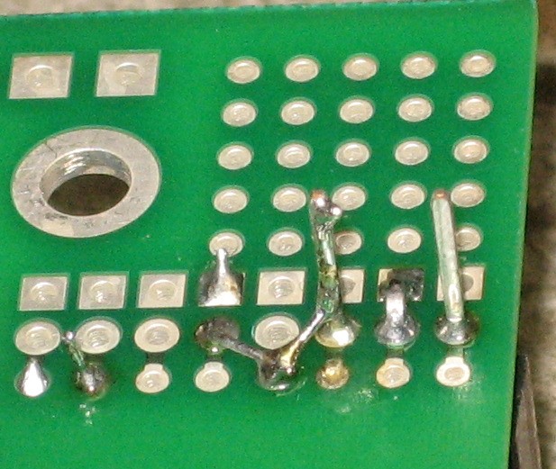
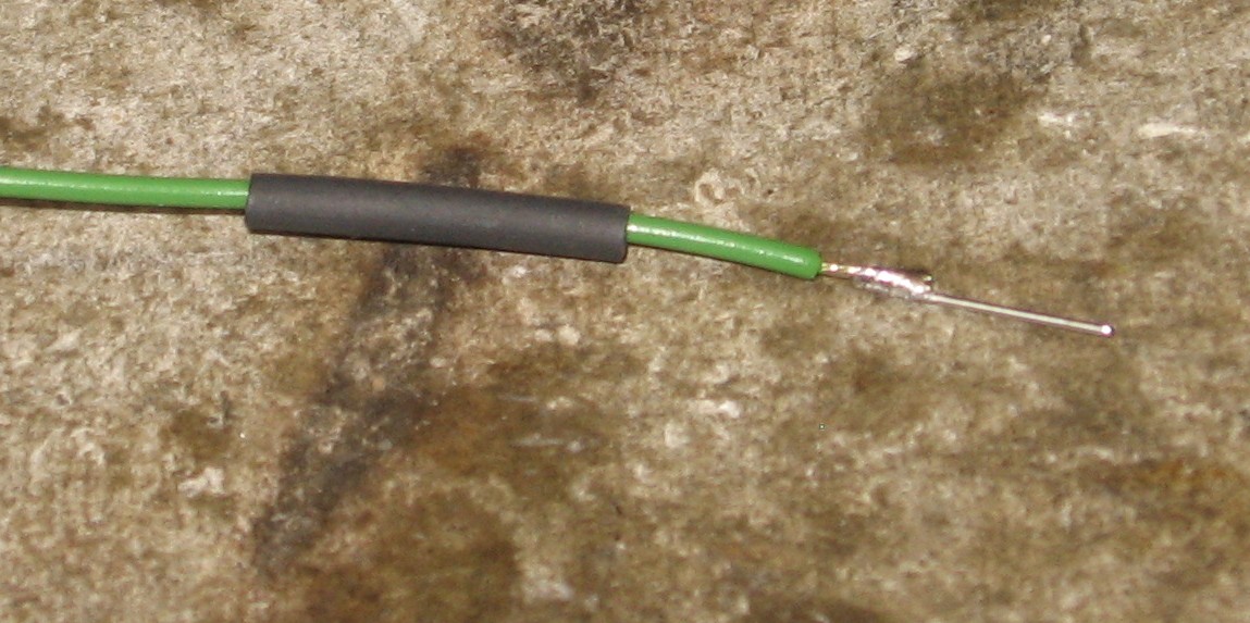
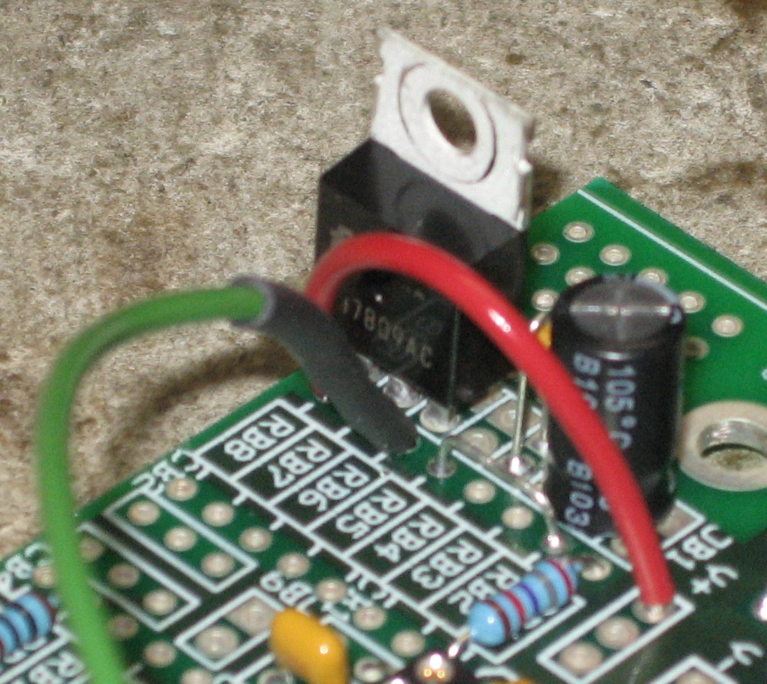
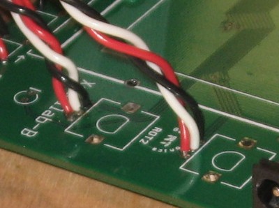
Now - in the course of messing around with the layout of this section of the PCB, we got some solder in the RB8 left side pad, so we couldn't get the green wire to fit into it. So we soldered a bit of resistor lead onto the wire. If you're building this thing, you won't have made our mistake and so your green wire will fit (just barely) in the hole of the RB8 pad:
the red and green (wire 3) wires connected:
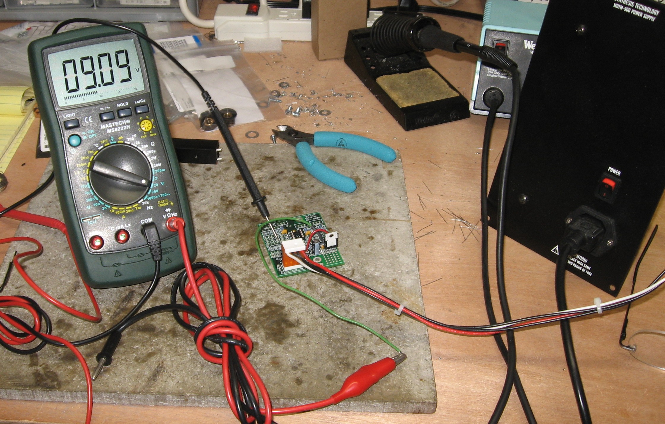
Even before we have the other wires connected, we wanted to test it. We haven't calibrated the output of the Power One - it's sitting at 15.15V - but the output of the LM7809 is 9.09V - close enough for now - at least we know it's working.
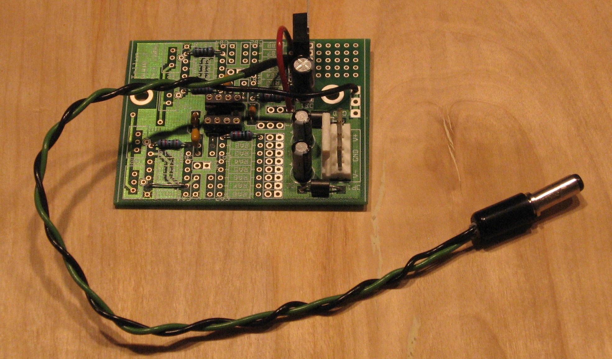
We soldered on the power plug
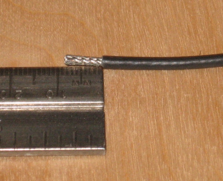
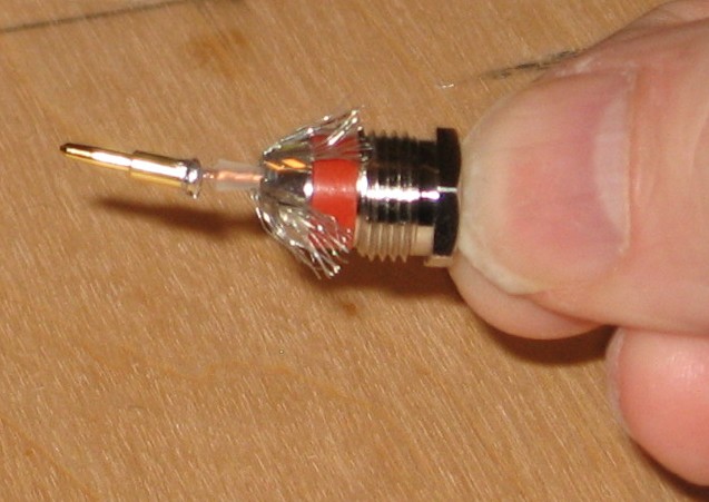
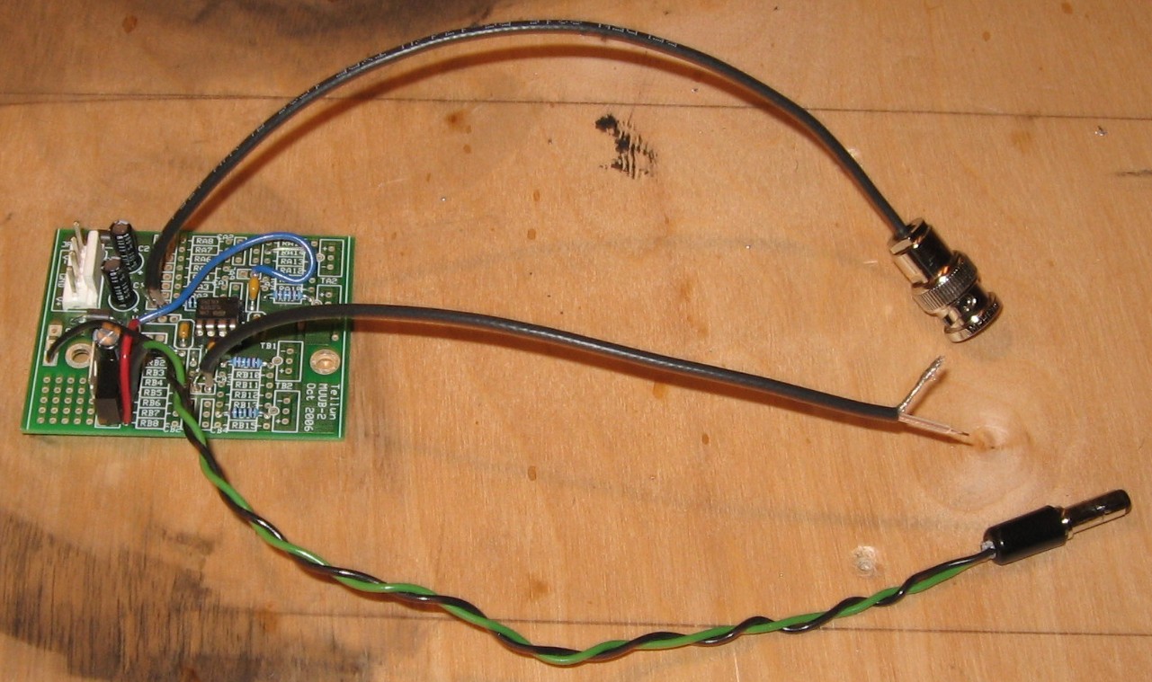
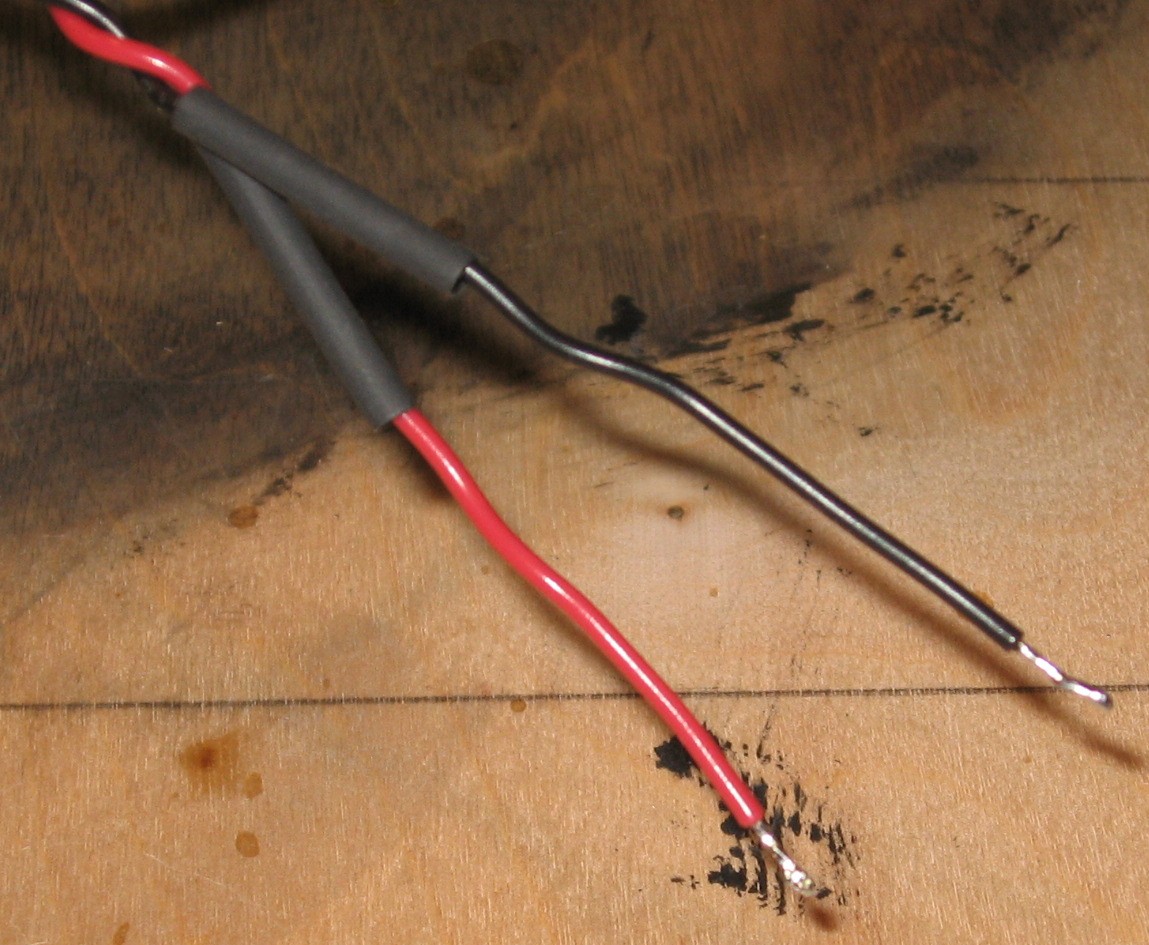
So - on with the rest of the Daughterboard construction: We soldered a 3 in. wire from JA9 (signal side) to JB1 (signal side). We soldered coax (wire #2) into JB9 for the output jack. The Xminilab B Analog Output J2 will be fed into the MUUB2 Amplifier/Inverter using the BNC connectors. If the BNC connector wasn't soldered into the Xminilab B PCB, we could just solder the wires directly. So we had to attach coax (wire #1) to the BNC plug per the instructions on the spec sheet (click here to see the pdf). Strip coax 8mm.
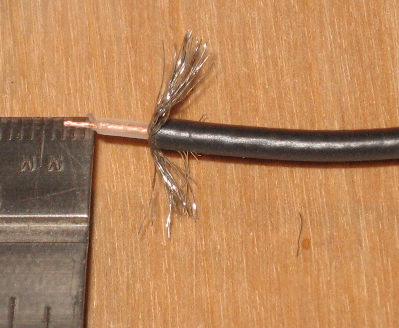
comb out shield braid and strip signal wire 3mm.
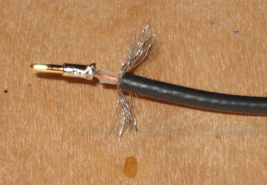
Solder pin to signal wire.
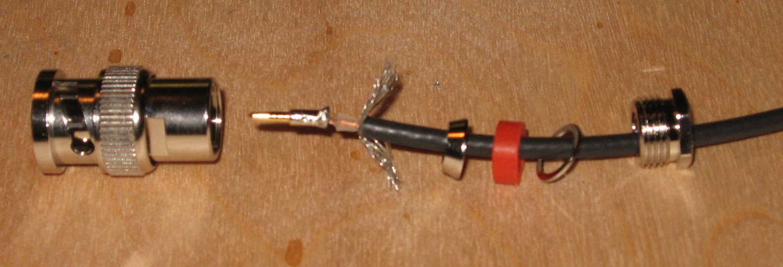
slip components onto wire.
push back shield strands.
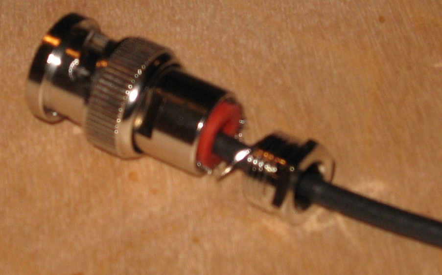
slip into plug.
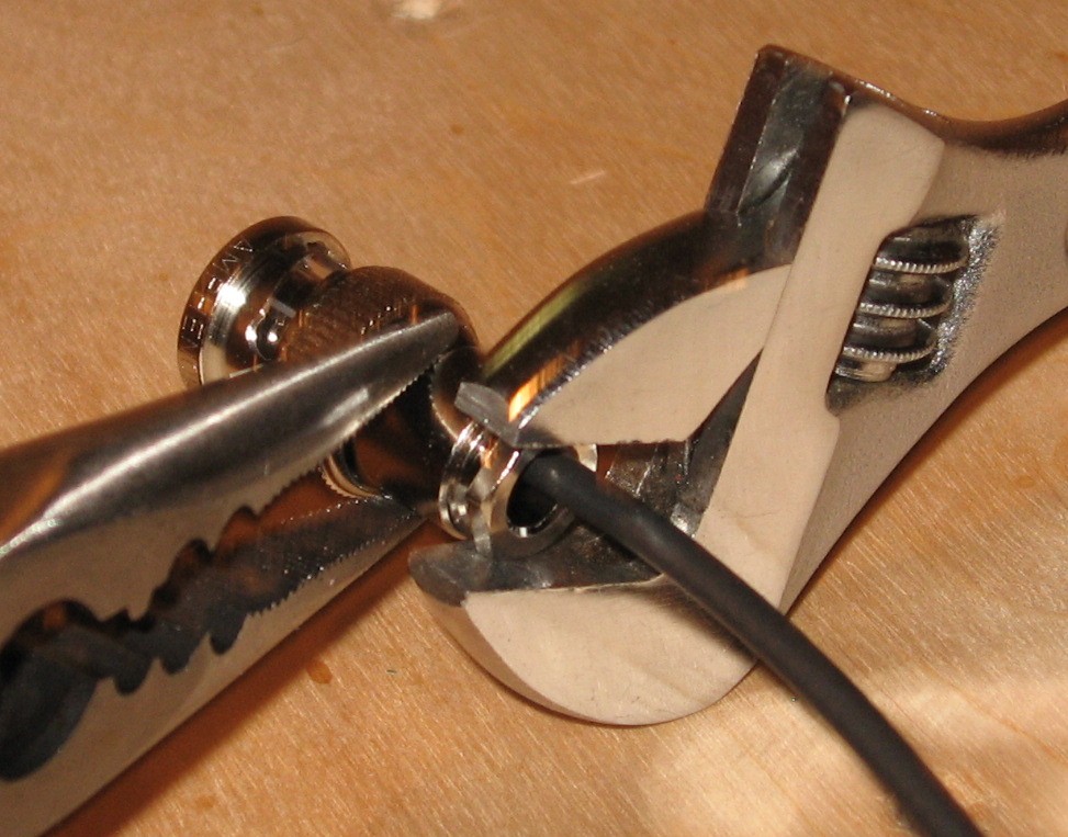
tighten.
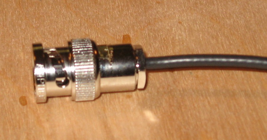
done.
TA DA!
|
||||||||||||||||||||||||||||||||||||||||||||||||||||||||||||||||||||||||||||||||||||||||||||||||||||||||||||||||||||||||||||||||||||||||||||||||||||||||||||||||||||||||||||
|
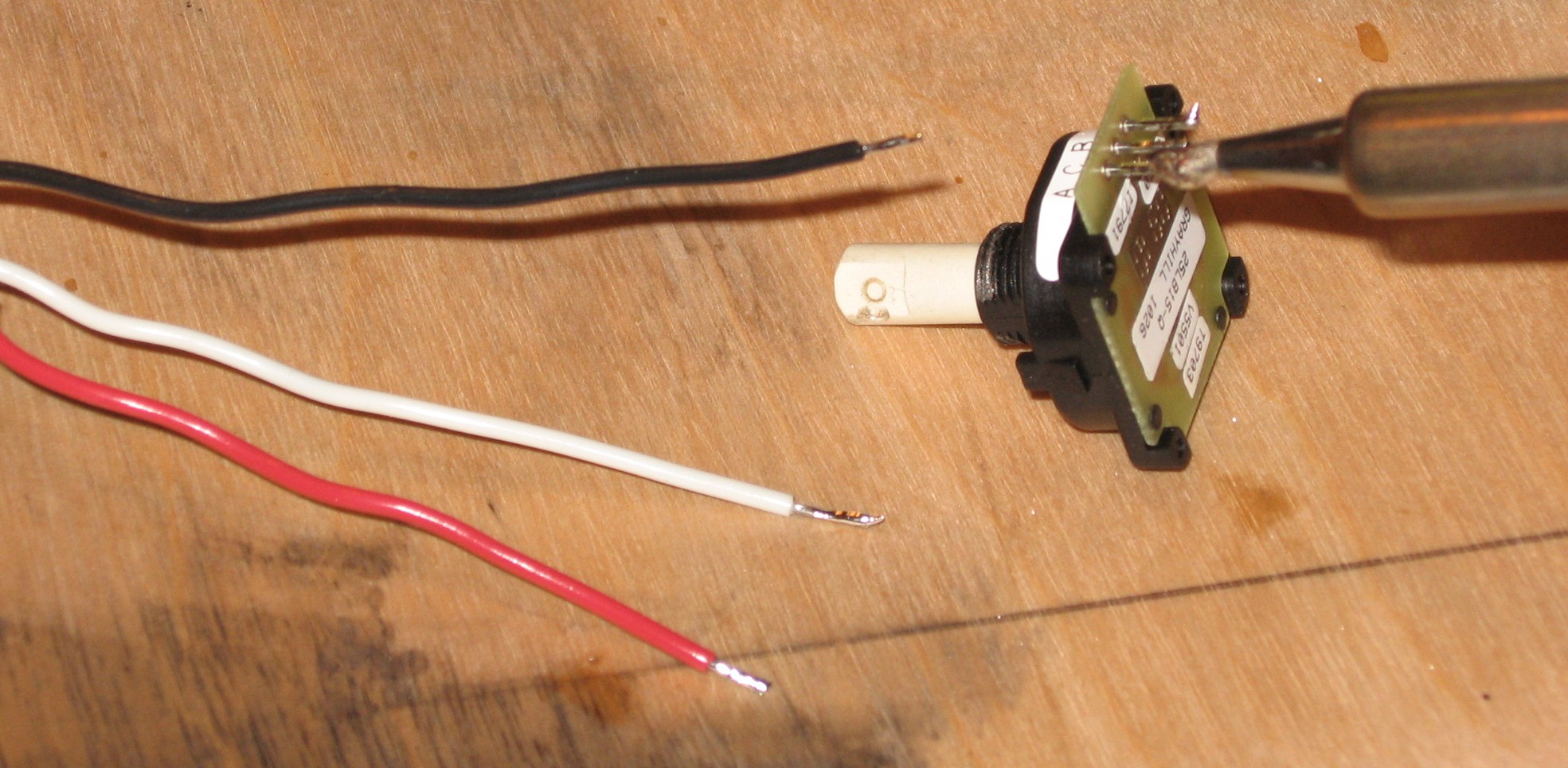
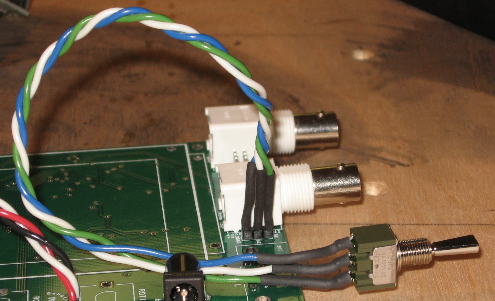
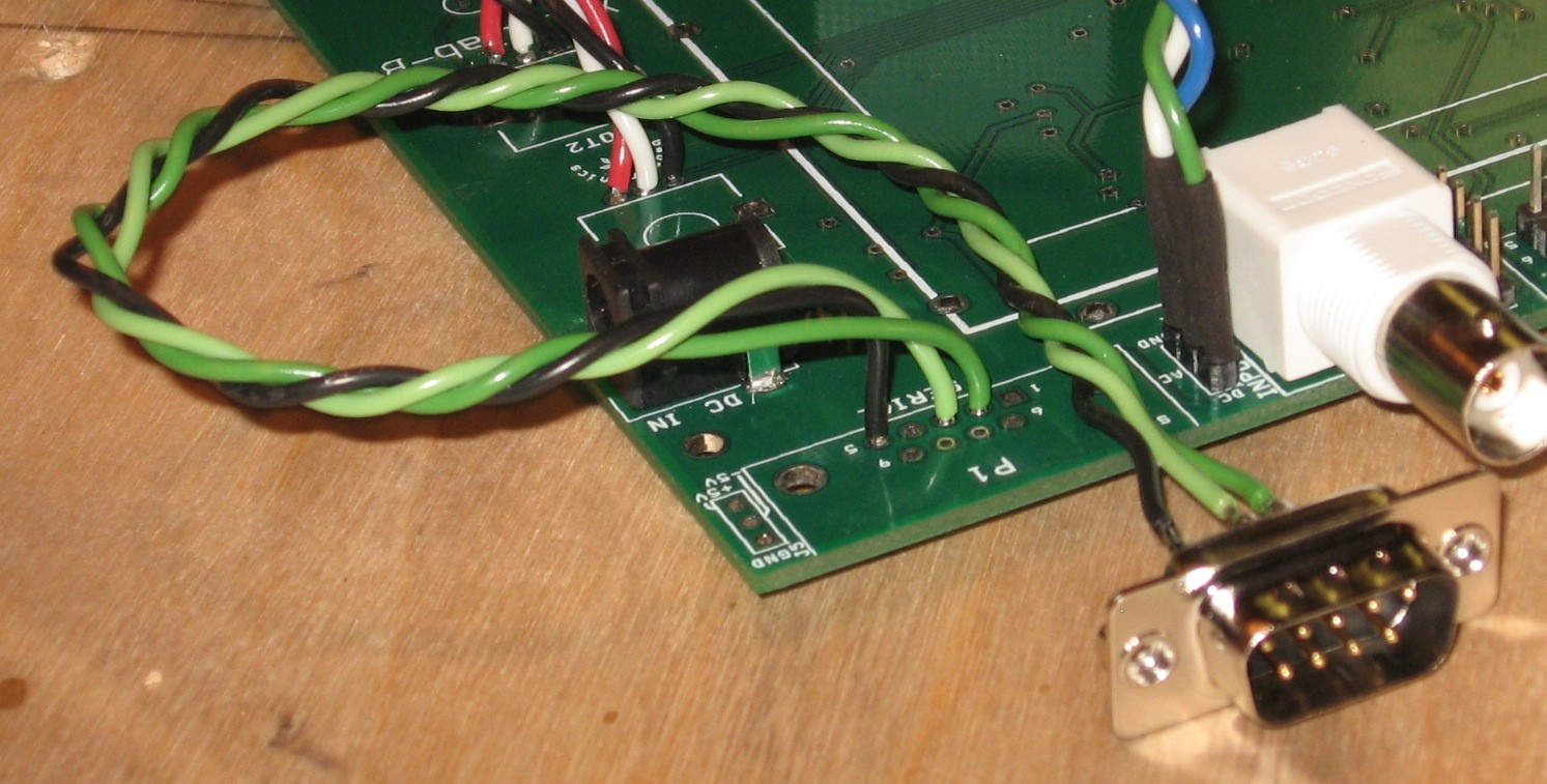
April, 2011 - Prepare Xminilab B ConnectionsThe tactile switches K1 through K7 (wires 5, 6, 7, 8, 9, 10, 11)
Tactile switch
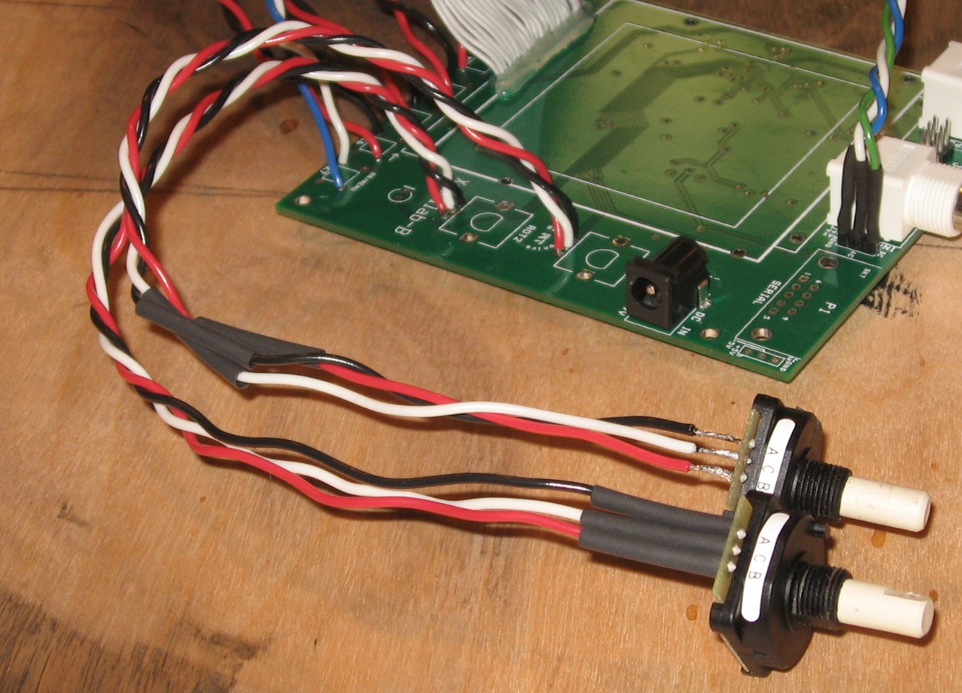
Rotary Encoders ROT1 & ROT2 - wires 15a, b, c and 16a, b, c
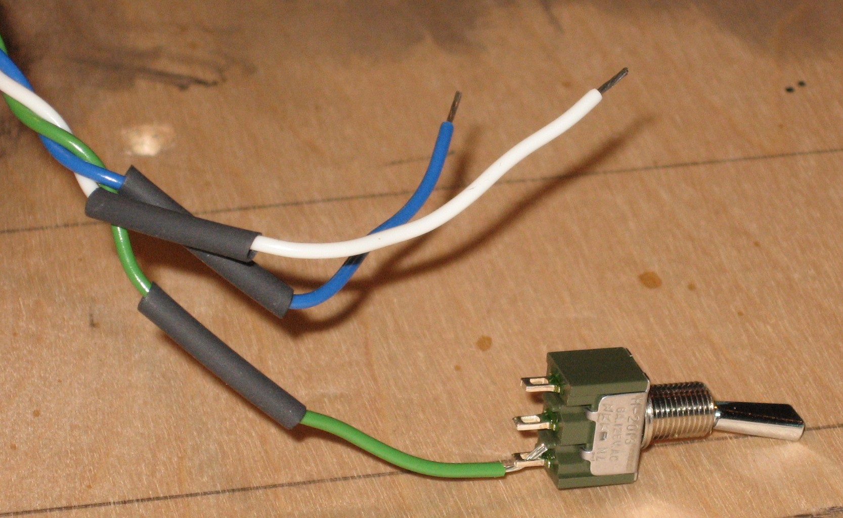
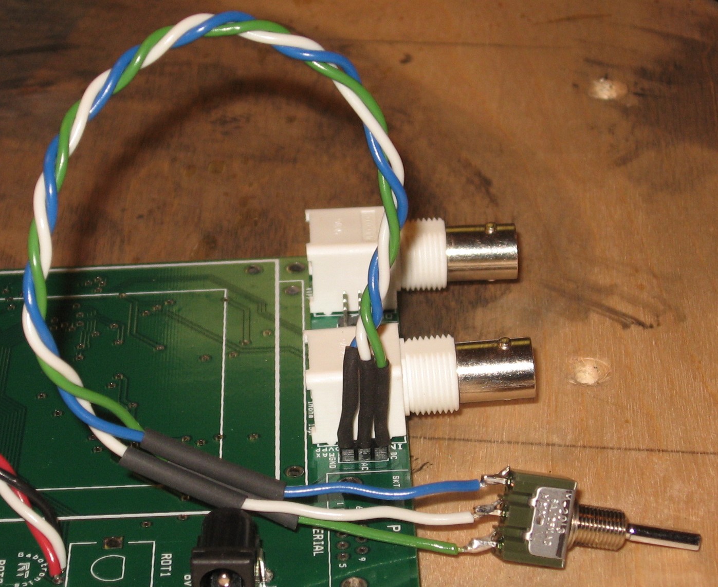
AC / DC / Ground switch - wires #12a, #12b, #12c
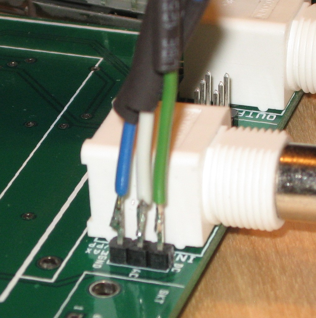
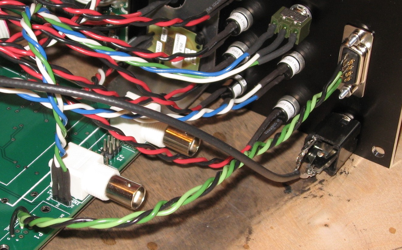
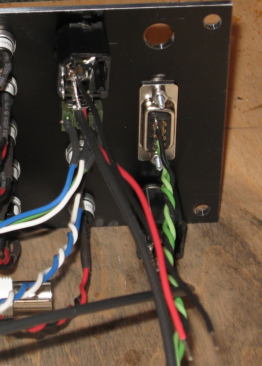
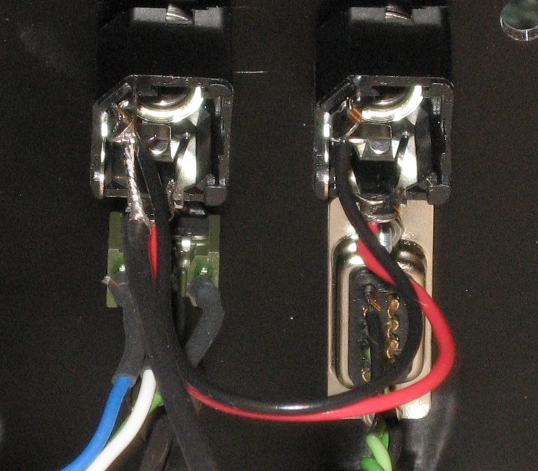
serial port - wires #18a, #18b, #18c
LED wires - wires #17a & #17b
Input Jack - Wire #13 (with BNC plug) and wires #14a and #14b.
|
||||||||||||||||||||||||||||||||||||||||||||||||||||||||||||||||||||||||||||||||||||||||||||||||||||||||||||||||||||||||||||||||||||||||||||||||||||||||||||||||||||||||||||
|
|
||||||||||||||||||||||||||||||||||||||||||||||||||||||||||||||||||||||||||||||||||||||||||||||||||||||||||||||||||||||||||||||||||||||||||||||||||||||||||||||||||||||||||||
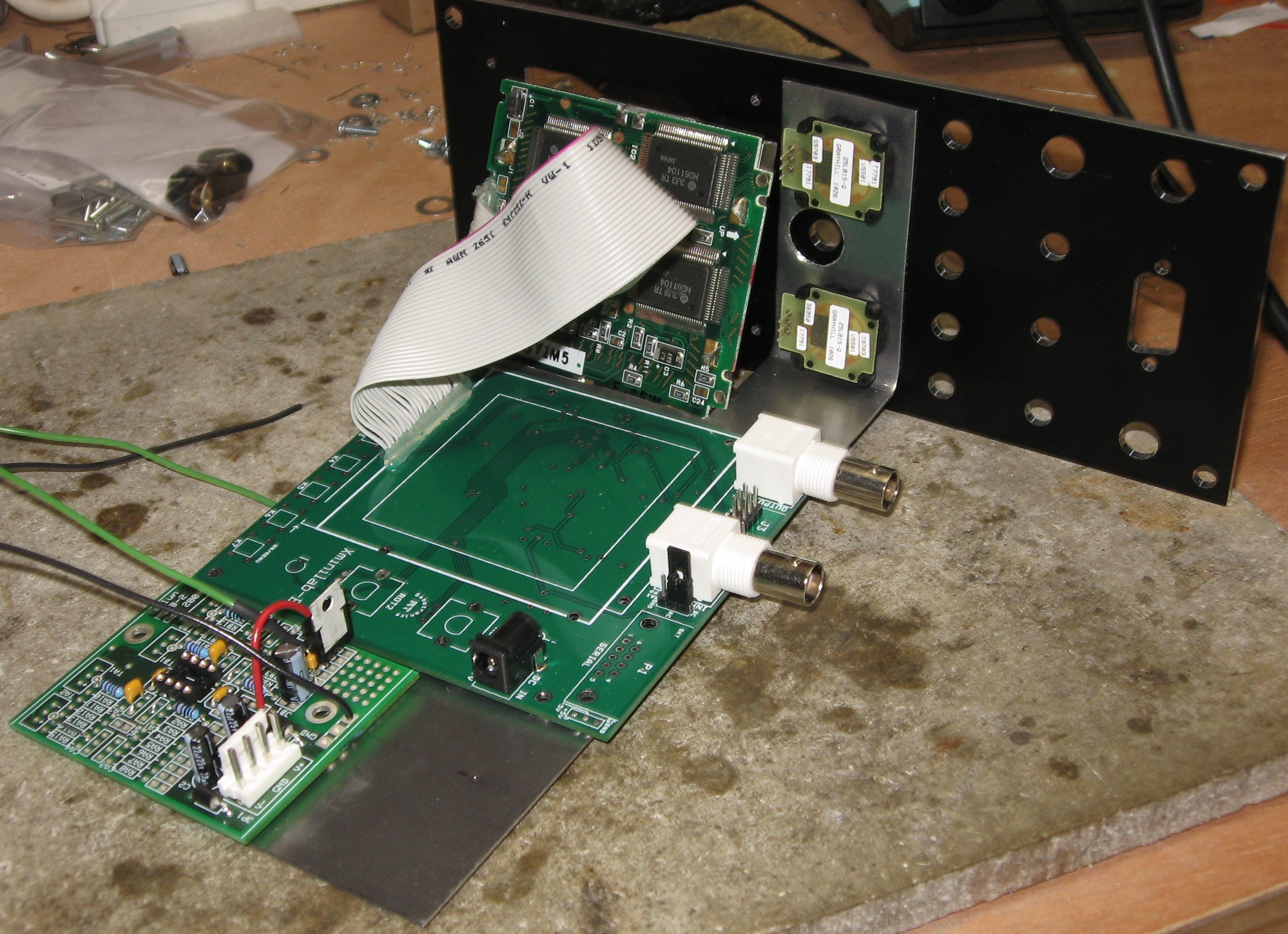
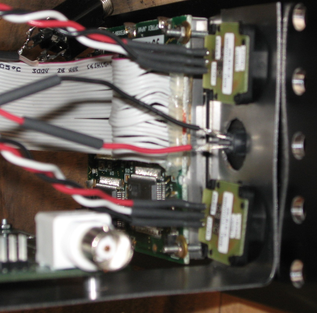
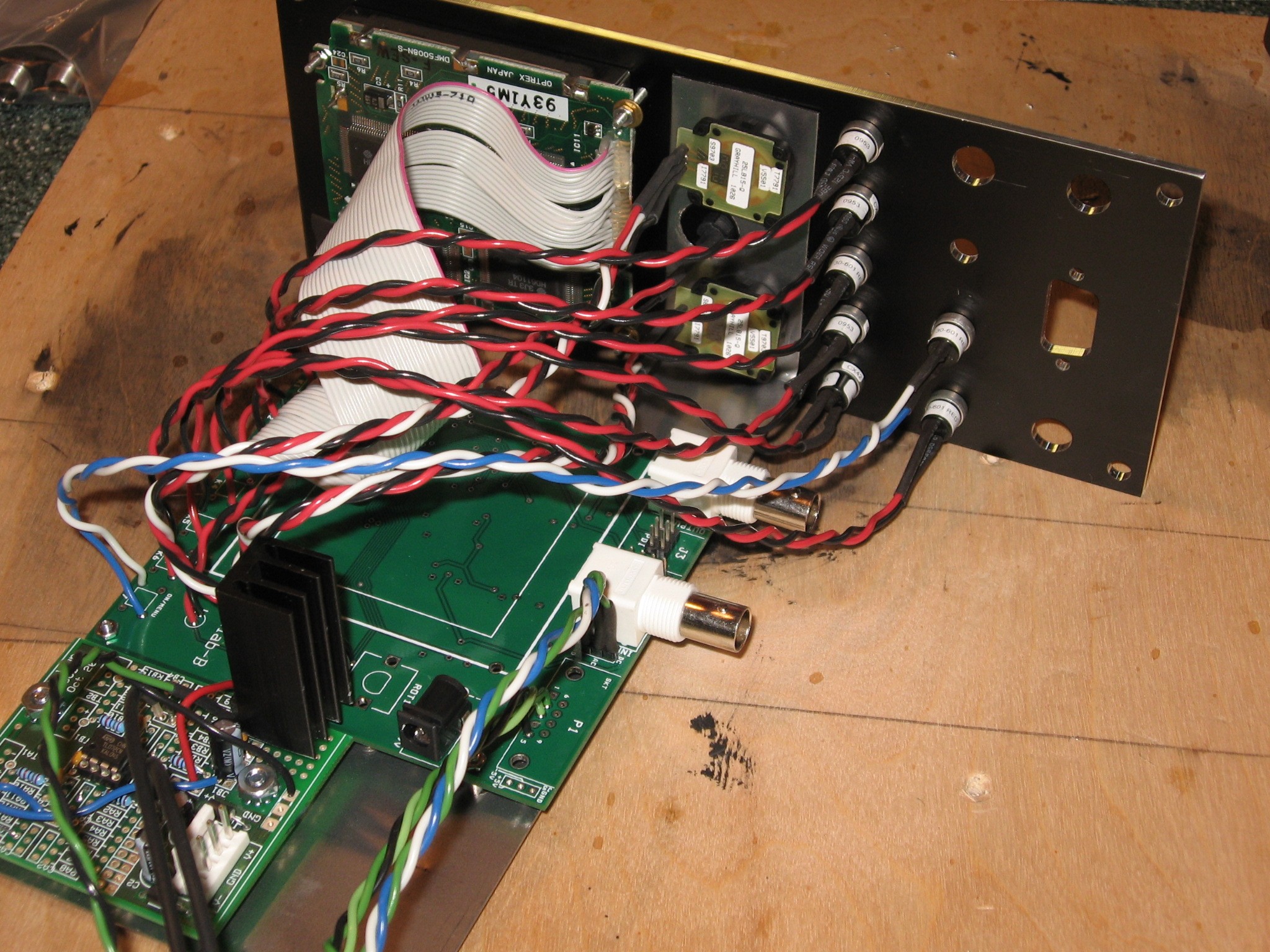
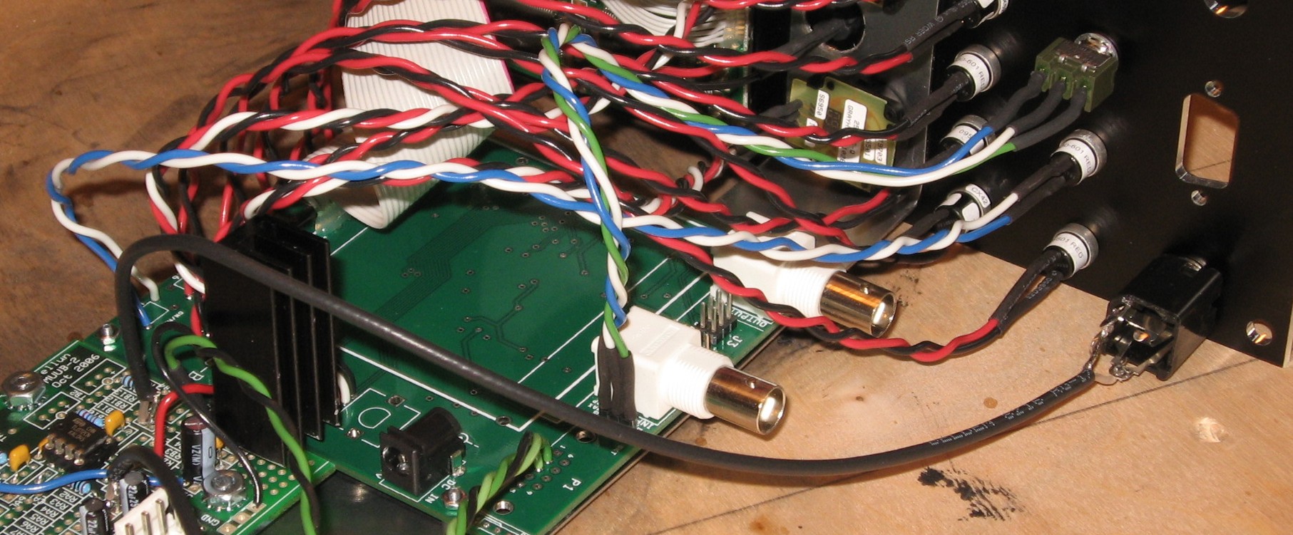
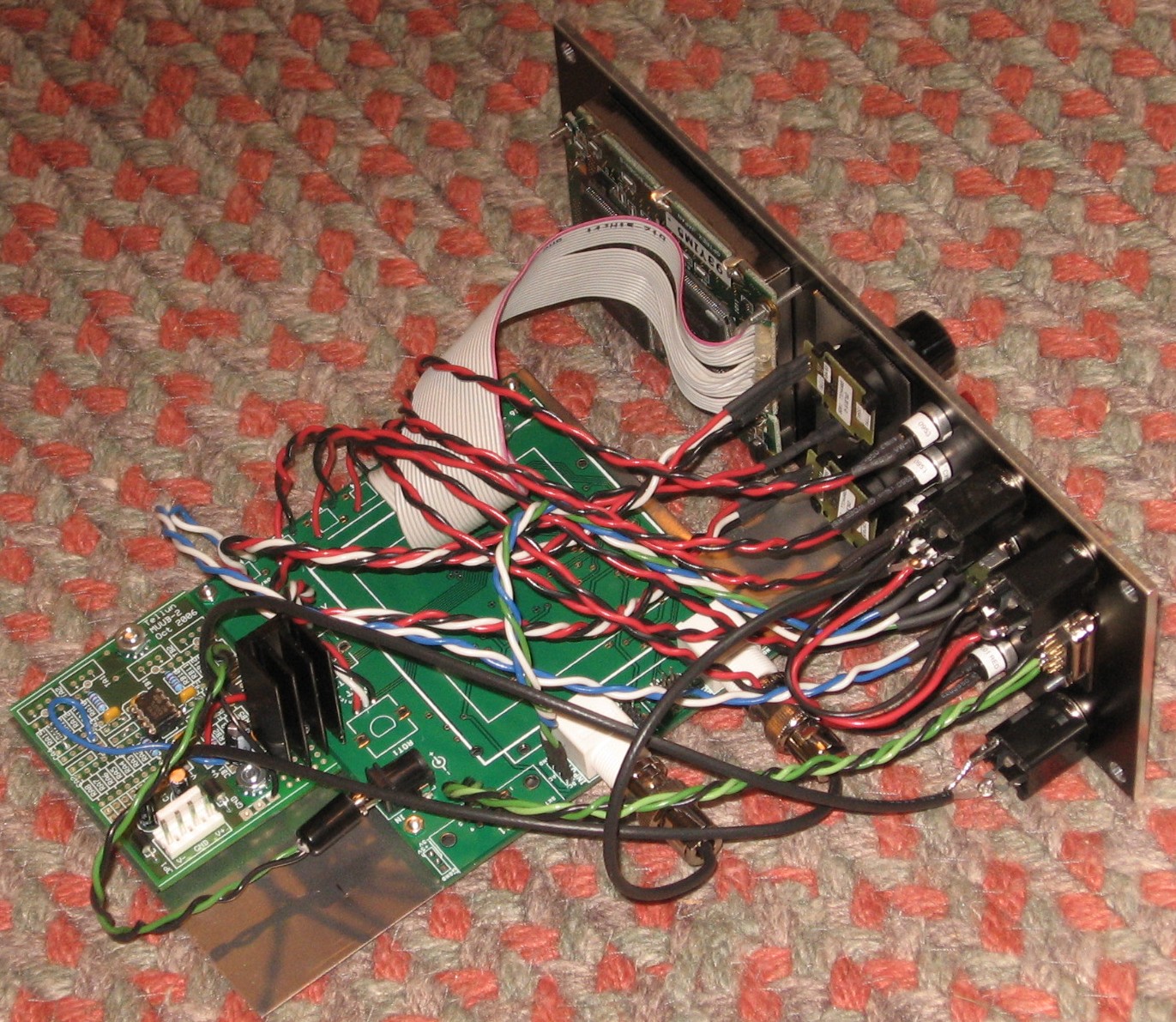
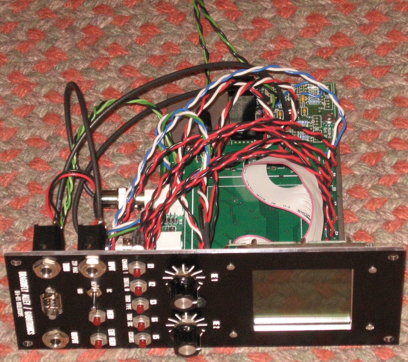
AssemblyPCBs mount on bracket
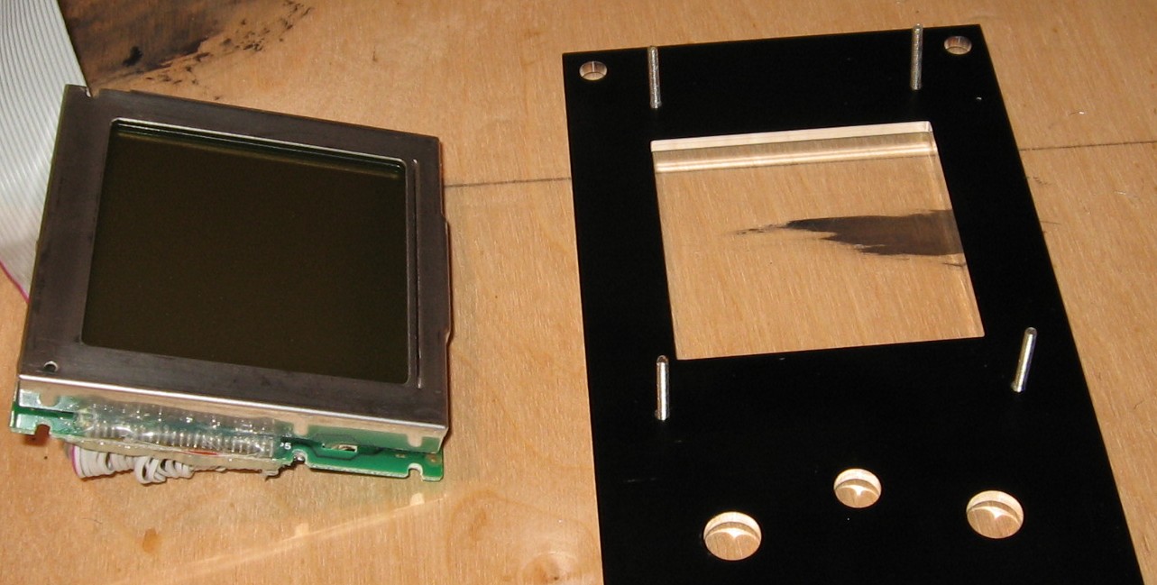
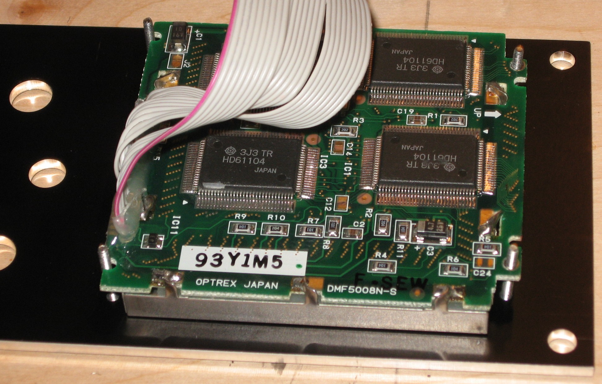
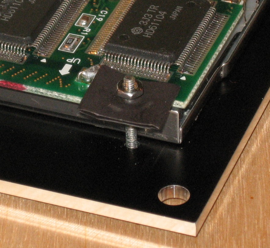
Screen mounts on panel
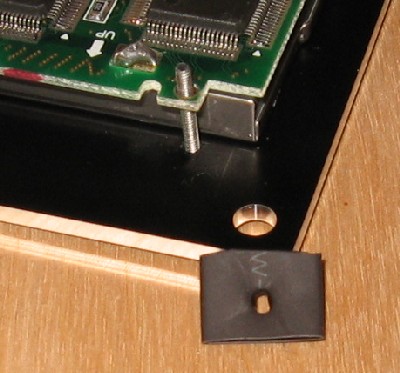
So check out how the upper right screw hole has these pads really close to it... the nut can touch those pads. So we used some big heat-schrink to make an insulative washer.
Attach bracket
Attach LED - red to the anode (long) lead and black to the cathode (short) lead
Momentary switches
Output Jack
Serial Port
Input Jack
Through Jack
Power plugged in...
BNC connectors plugged in...
Done
|
||||||||||||||||||||||||||||||||||||||||||||||||||||||||||||||||||||||||||||||||||||||||||||||||||||||||||||||||||||||||||||||||||||||||||||||||||||||||||||||||||||||||||||
Set up / Testing |
||||||||||||||||||||||||||||||||||||||||||||||||||||||||||||||||||||||||||||||||||||||||||||||||||||||||||||||||||||||||||||||||||||||||||||||||||||||||||||||||||||||||||||
Use Notes |
||||||||||||||||||||||||||||||||||||||||||||||||||||||||||||||||||||||||||||||||||||||||||||||||||||||||||||||||||||||||||||||||||||||||||||||||||||||||||||||||||||||||||||
|
|
||||||||||||||||||||||||||||||||||||||||||||||||||||||||||||||||||||||||||||||||||||||||||||||||||||||||||||||||||||||||||||||||||||||||||||||||||||||||||||||||||||||||||||


|
The fine Print: Use this site at your own risk. We are self-proclaimed idiots and any use of this site and any materials presented herein should be taken with a grain of Kosher salt. If the info is useful - more's the better. Bill and Will © 2005-2011 all frilling rights reserved
|