back to my homepage

JH. Krautrock Phaser
(a. k. a. "Compact Clone" - insprired by the Schulte Compact A Phasing)


Background

If you listen to German records from the 1970's, you often hear a rather unique phasing that comes from a device called "Compact A Phaser" from the Berlin company "Gert Schulte Audio Elektronik". It's often referred to as "Schulte Phaser", and I have heard it being called "Krautrock Phaser", "Schulze Phaser" (because it's prominent on many early KS albums), "TD Phaser" (because of Tangerine Dream). In my opinion, this phaser has been important to the sound of these early electronic musicians almost as much as the synthesizers the used.

My Compact Clone from 1999

In 1999 I have built a clone of this on veroboard, and put it into the enclosure you can see in the pictures below.
This has been partially sponsored by the vintage synthesizer shop Touched by Sound back then, who also have taken my Phaser to NAMM to test the waters for commercial production. Well, it didn't come to this for various reasons, but I've been enjoying my Compact Clone ever since, and mostly use it on my Korg Lambda string ensemble.
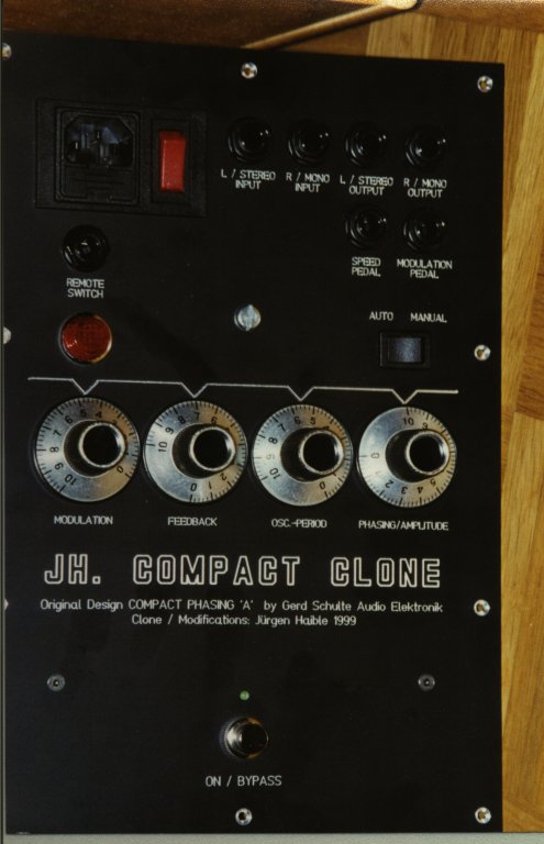

Front panel view (click on image to enlarge)
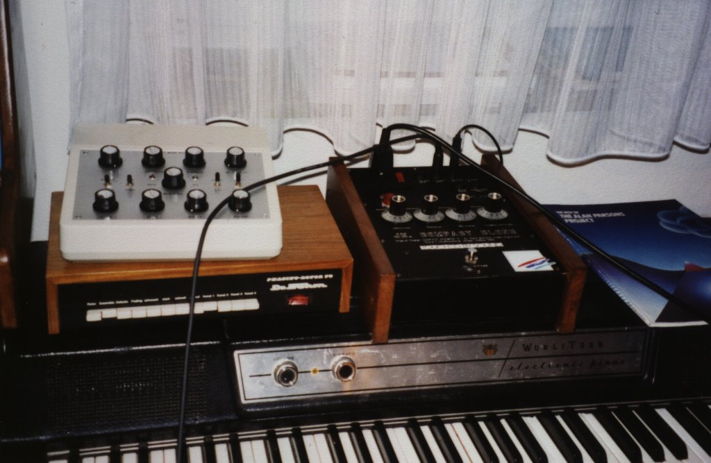
With wooden cheeks (click on image for greater picture)


The new Compact Clone 2007

I've decided to do another redesign of that circuit and make a PCB layout.

All who have followed my DIY projects over the years know that I'm using the term "clone" rather loosely.
I'm not actually "cloning" anything, which would be a 1:1 reproduction of the original circuit and/or the appearance.
I certainly do strive for a most perfect reproduction of the sound that made a vintage design famous, but I also add features of my own that I find usefull, and tayler the circuit to my own needs and standards.

In case of the Compact Clone this means:

Things I keep
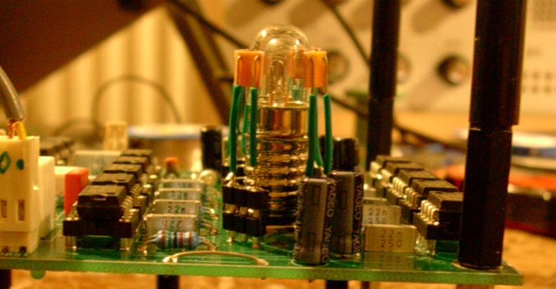
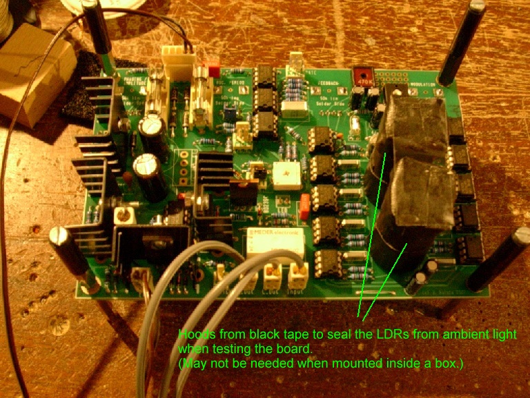
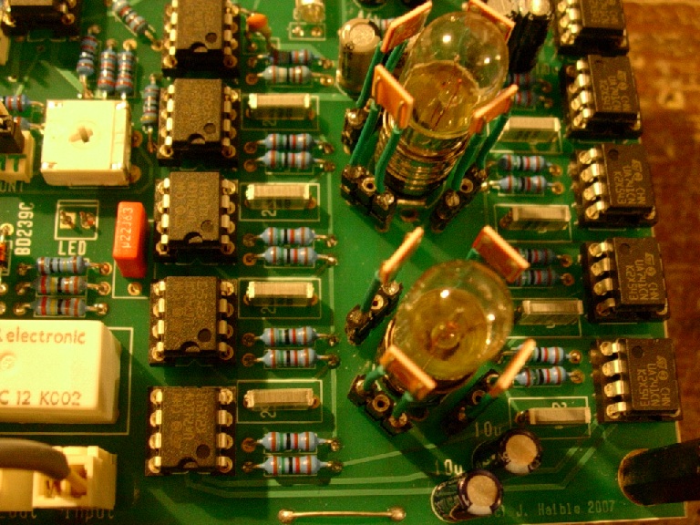
The incandescent lamp / LDR combination that is responsible for the unique way of sweeping
Big incandescent lamp as sweep indicator on front panel
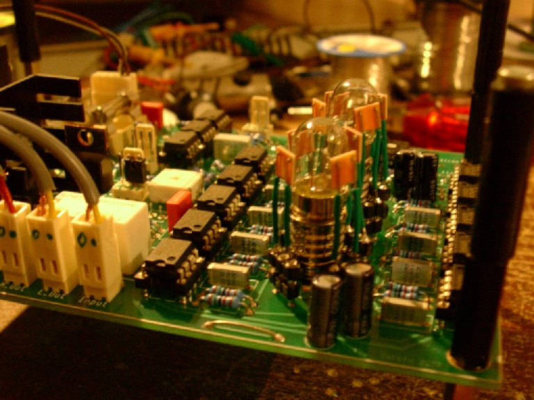
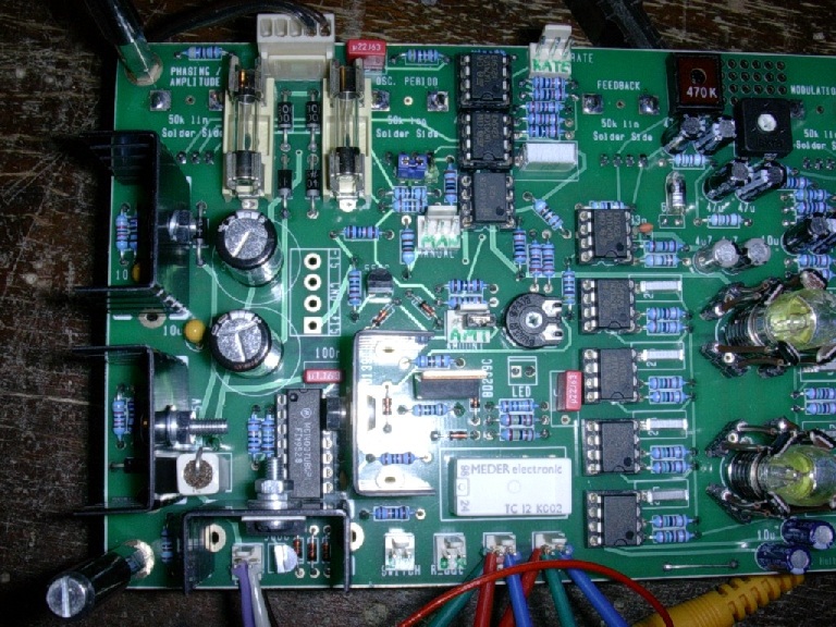
The circuit topology: 8 Stages of Phasing, 2 Stages of Feedback. Negative, lowpass-filtered feedback
The 741 opamps
The unique "Osc. Period" potentiometer that has maximum LFO rate on ccw end. (optional)
Works with original 7V 100mA lamps.
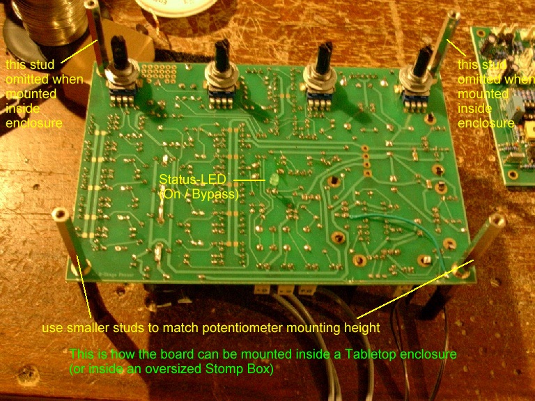
The possibility to mount potentiometers direcly on board. (Alps RK11 vertical mount types or similar.)
Of course you can connect about every other potentiometer with wires, too.
Mains-Powered (optional). For +/-15V powered, see below.
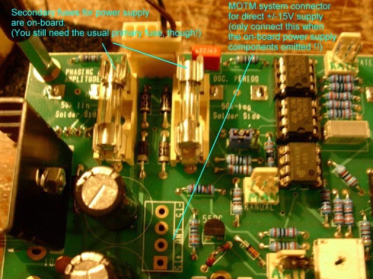
Power supply for mains powering on the PCB, including secondary fuses, rectifiers, electrolytic caps, voltage regulators and heatsinks.

Things I change
It's possible to adapt the circuit to slightly different lamps and LDRs.
I've added a lot of coupling capacitors to keep offset voltages from the outputs
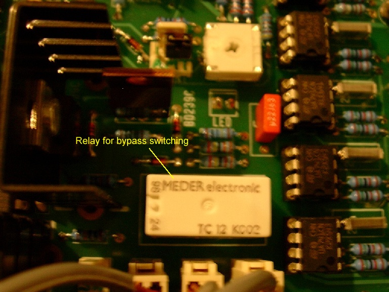
A Hard-Bypass with a relay that is controlled by an momentary switch. (Push: Turn on. Push again: Turn off.)
Several of these switches can be wired in parallel, i.e you can have on on the front panel, and another one connected via jack for remote control.
Circuit redesigned for easily available potentiometers: 50k lin  and 50k log  (47k is the same, actually.)
It's also possible to adapt it for slightly different pot values (feel free to ask), if your favorite form factor of potentiometer only comes in certain values.
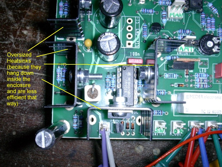
You don't need that special "staircase" enclosure when using pcb-mounted potentiometers. In my version, the pots are mounted on the solder side of the board. So the component side looks down inside the enclosure, not being in th eway of the front (or rather "top") panel.
Complete redesign for +/-15V operation. Option for MOTM-style power connector on the PCB.
Large heatsinks and stronger Lamp Driver transistors.
Mains transformer and primary fuse not on PCB for safety reasons.
No DIN jack.
Switch for LFO / Manual sweep on front panel
1/4" TRS jacks for remote control of Sweep Rate and Modulation Depth.


Sound Samples

The first three sound samples are from my 2000 Album "Dark November".  The arpeggiated notes from the OB-8 are treated with the Compact Clone. In the first sample, it's rather tame. At the beginning of the second sample, the unique resonance Phaser kicks in.
Second Loop 1 (1.172 MB)
Second Loop 2 (1.172 MB)
Second Loop 3 (1.172 MB)

Schematics

NEW: PDF document with schematics of on-board components (and some hints how to cennect off-board components, too.)

The PCB

Here's a preview of what the PCB will look like (preliminary version):


Click on the image for a larger view of the components.

NEW: Component overlay with reference designators instead of component values. (Very useful for debugging and modifications)

NEW: Component overlay with component values (as silkscreened on the board)

Bill of Materials

Here's a list of components that I've used: Krautrock Phaser BOM.
It only contains the components that are soldered to the board, no front panel components.
You'll want to have a nice "retro" looking lamp holder on th efront panel, too.
The incandescent lamp for the front panel is the same type as the two for illuminating the LDRs.
In Europe, E10 sockets are probably more common than elsewhere in the world. You can choose whatever socket you want - it just has to fit the lamp you're using. You can also simply solder the lamps to the PCBs with short, stiff wires, if you don't find a socket that fits into the PCB.
The lamps I'm using are 7V / 100mA types - spec'ed the same as in the original Compact A Phasing. If you cannot get these, you can try with 6.3V lamps of approximately the same power (0.7 Watt). In that case, you have to connect two 1N4002 diodes in series with these lamps. The PCB has the necessary pads and holes for this already, but I have not tested 6.3V lamps myself.

IMPORTANT: Safety and Thermal Issues

I once had an original Compact A for testing, and I've been quite shocked about open mains voltage on the printed circuit board. No, I didn't get an electrical shock, but I could have. Also, some of the components became very hot, and the transistors had very small heatsinks. This is in no way meant for bashing the original design - it may just have been that particular specimen, and it may have been tampered with (modified) - who knows.
What I want to say is this:
We're driving incandescent lamps here, and these need more current than LEDs, so the transistors which drive them will get hot, the voltage regulators will get hot, so we have to cool them. There are 4 rather big heat sinks on the board. Thes will help to dissipate the heat into the interior of the phaser enclosure. Now, that enclosure should be sealed against light from the outside, because of the LDRs. This means it will also be sealed for heat, more or less. A possible solution is to use a metal enclosure, or at least an enclosure with a large metal front panel. Keep in mind that the heat transfer then goes like this:
Transistor -> heatsink -> air inside enclosure -> metal enclosure -> air outside enclosure.
This is why the heatsinks on the board are rather oversized (yet unexpensive), and why you should have a metal enclosure or large metal front panel.
In my first prototype, I have wrapped each Lamp + 4 LDRs combination with a black adhesive tape, to further improove shielding against light.
With this, you don't need an enclosure that is sealed against light. But you must be careful about your choice of adhesive tape: It must be safe against ignition. Ok, the incandescent lamps should only get warm, not hot - the circuit is designed to run the lamps well below their nominal current rating, to increase their life-span. But you must make sure that there are no errors that cause a higher current to flow, before you apply any tape around the lamps. Run the circuit for a while, and carefully check the warmth of the lamps with your fingers.
There are many ways to build a phaser with these PCBs, and I cannot check every possible way how it could be done. In short: I just provide the boards, but you are responsible for safety.


Compact Clone 2007 Prototype Pictures


(to be continued ... )

 back to my homepage