Bill and Will's Synth
| |||||||||||||||||||||||||||||||||||||||||||||||||||||||||||||||||||||||||||||||||||||||||||||||||||||||||||||||||||||||||||||||||||||||||||||||||||||||||||||||||||||||||||||||||||||||||||||||||||||||||||||||||||||||||||||||||||||||||||||||||||||||||||||||||||||||||||||||||||||||||||||||||||||||||||||||||||||||||||||||||||||||||||||||||||||||||||||||||||||||||||||||||||||||||||||||||||||||||||||||||||||||||||||||||||||||||||||||||||||||||||||||||||||||||||||||||||||||||||||||||||
Table of Contents |
|||||||||||||||||||||||||||||||||||||||||||||||||||||||||||||||||||||||||||||||||||||||||||||||||||||||||||||||||||||||||||||||||||||||||||||||||||||||||||||||||||||||||||||||||||||||||||||||||||||||||||||||||||||||||||||||||||||||||||||||||||||||||||||||||||||||||||||||||||||||||||||||||||||||||||||||||||||||||||||||||||||||||||||||||||||||||||||||||||||||||||||||||||||||||||||||||||||||||||||||||||||||||||||||||||||||||||||||||||||||||||||||||||||||||||||||||||||||||||||||||||
|
This page has become really long, so here's a table of contents that we hope will make it easier to traverse: Background - presents our thinking about our power distribution system Parts - presents a Bill of Materials and notes about it |
|||||||||||||||||||||||||||||||||||||||||||||||||||||||||||||||||||||||||||||||||||||||||||||||||||||||||||||||||||||||||||||||||||||||||||||||||||||||||||||||||||||||||||||||||||||||||||||||||||||||||||||||||||||||||||||||||||||||||||||||||||||||||||||||||||||||||||||||||||||||||||||||||||||||||||||||||||||||||||||||||||||||||||||||||||||||||||||||||||||||||||||||||||||||||||||||||||||||||||||||||||||||||||||||||||||||||||||||||||||||||||||||||||||||||||||||||||||||||||||||||||
Background |
|||||||||||||||||||||||||||||||||||||||||||||||||||||||||||||||||||||||||||||||||||||||||||||||||||||||||||||||||||||||||||||||||||||||||||||||||||||||||||||||||||||||||||||||||||||||||||||||||||||||||||||||||||||||||||||||||||||||||||||||||||||||||||||||||||||||||||||||||||||||||||||||||||||||||||||||||||||||||||||||||||||||||||||||||||||||||||||||||||||||||||||||||||||||||||||||||||||||||||||||||||||||||||||||||||||||||||||||||||||||||||||||||||||||||||||||||||||||||||||||||||
|
So we're building this chart to do a nearly accurate calculation. For the modules we don't really know the value for we took a guess on the high side and marked them with a tilda.
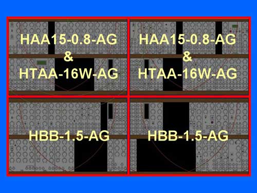
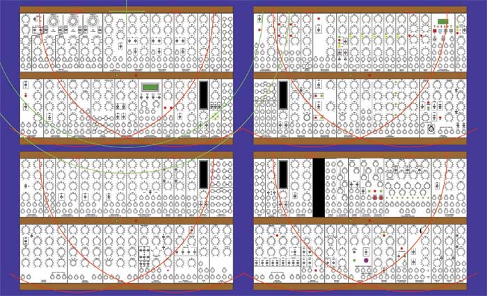
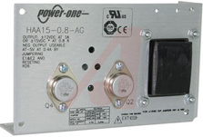
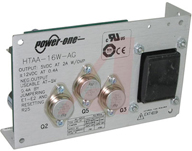
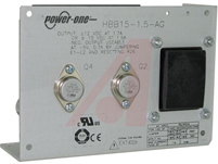
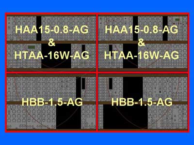
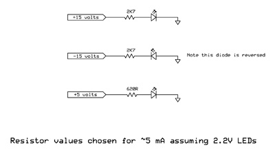
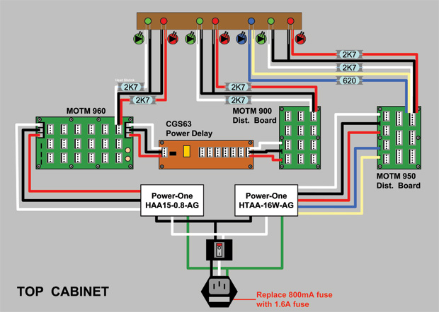
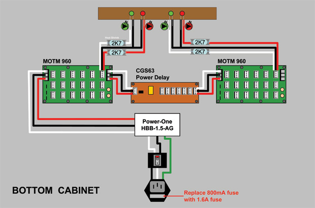
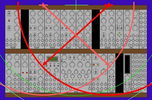
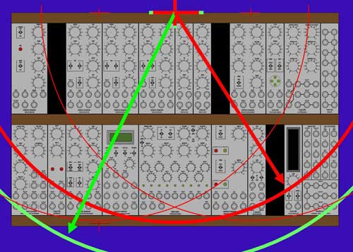
Supply We ordered four power supplies from Paul - two each of the 900s and 950s - so we'd have four panels - one each for our cabinets with plug, fuse, and switch. But instead of mounting the power supply units and power distribution boards on the panels, we'll mount them separately in the cabinets. Each 900 has an HAA15-0.8-AG dual Power-One (click here for .pdf spec sheet). Each 950 has an HTAA-16W-AG Power-One (Click here for .pdf spec sheet). We'll put one HAA15-0.8-AG and one HTAA-16W-AG in each top cabinet (that's where the +5V is needed). In each of the bottom cabinets, we'll put an HBB15-1.5-AG; 1.5 amps of +/- 15V. Indicators We want to have LEDs to indicate when the power is on - green for each +15V "rail," red for each -15V "rail," blue for each +5 "rail." We didn't know exactly how to go about it, so we asked Dave Brown. He wrote us back: "LEDs on all three supplies is a good idea. I always make sure that there are modules on every power supply that have LEDs. The brightness of the LED will tell you that the voltage is reasonable, but not accurate. For example, if for some reason the +15 was only at +12, the LED brightness would probably be indistinguishable. "...Sometimes a power supply will "crowbar" meaning the inrush current was sufficiently high that it goes into current limit. LEDs will tell you that they all came up. "Figure out how much current you want to drive the LEDs with for a reasonable brightness. If they are all the same, then make each of the currents be the same. LED brightness varies with color and efficiency so I run my blue LEDs on much less current. Also, the voltage drop varies with color. "Assume a standard red LED with 2.0 volt drop. 3 - 5 mA would be enough current. "For the +15 volts supplies: (15-2.0)/5 mA = 2600 ohms. Use probably the next higher value, so 2K7. Use this for both the + and - 15 volts supplies. For the -15 volt supply, just turn the diode around. Connect the cathode to -15 and the anode to ground. "For +5 volts, you want the current to be the same. Use the same formula to find that resistor. Using 2K7, (15-2.0)/2K7 = 4.8 mA. (5-2.0)/4.8 mA = 625R. Use a 620 ohm resistor. "You could probably get away with higher resistance values. It depends on the brightness you want." But we're total idiots so we asked Dave to show us exactly how to do it. We mentioned that we were going to use a blue LED for the +5V indicator. He reminded that these are a little brighter that the green and red. He provided us with this little diagram - thank goodness - easy as cake. (Thanks Dave!) Distribution Here's the distribution plan for the top cabinets: Here's the distribution plan for the bottom cabinets: Power cables illustrated... The above synth layout (four cases - each two rows high and 18U wide) can be accomplished with a couple power cable layouts. One uses all standard 20" MOTM power cables, but with two distribution points. This may have advantages, given power distribution considerations:
Another layout is with mostly 20" power cables (red), but some custom 24" cables (or 30" cables) (green) and centrally located distribution.
|
|||||||||||||||||||||||||||||||||||||||||||||||||||||||||||||||||||||||||||||||||||||||||||||||||||||||||||||||||||||||||||||||||||||||||||||||||||||||||||||||||||||||||||||||||||||||||||||||||||||||||||||||||||||||||||||||||||||||||||||||||||||||||||||||||||||||||||||||||||||||||||||||||||||||||||||||||||||||||||||||||||||||||||||||||||||||||||||||||||||||||||||||||||||||||||||||||||||||||||||||||||||||||||||||||||||||||||||||||||||||||||||||||||||||||||||||||||||||||||||||||||
Parts |
|||||||||||||||||||||||||||||||||||||||||||||||||||||||||||||||||||||||||||||||||||||||||||||||||||||||||||||||||||||||||||||||||||||||||||||||||||||||||||||||||||||||||||||||||||||||||||||||||||||||||||||||||||||||||||||||||||||||||||||||||||||||||||||||||||||||||||||||||||||||||||||||||||||||||||||||||||||||||||||||||||||||||||||||||||||||||||||||||||||||||||||||||||||||||||||||||||||||||||||||||||||||||||||||||||||||||||||||||||||||||||||||||||||||||||||||||||||||||||||||||||
|
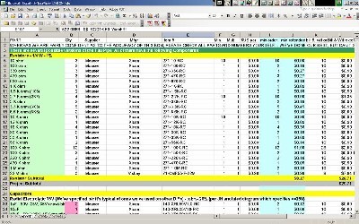
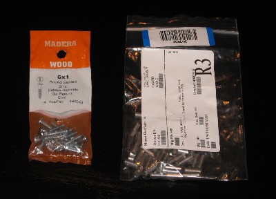
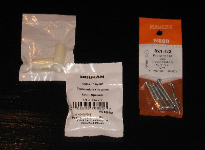
Will and I have developed a parts-lists / bill-of-materials in the form of an XL spreadsheet. Click here to download the spreadsheet (apx. 250K). 1/2 in spacers and 1 inch #6 screws for the distribution boards 1 in nylon spacers and 1-1/2 inch #8 screws for the power-ones | |||||||||||||||||||||||||||||||||||||||||||||||||||||||||||||||||||||||||||||||||||||||||||||||||||||||||||||||||||||||||||||||||||||||||||||||||||||||||||||||||||||||||||||||||||||||||||||||||||||||||||||||||||||||||||||||||||||||||||||||||||||||||||||||||||||||||||||||||||||||||||||||||||||||||||||||||||||||||||||||||||||||||||||||||||||||||||||||||||||||||||||||||||||||||||||||||||||||||||||||||||||||||||||||||||||||||||||||||||||||||||||||||||||||||||||||||||||||||||||||||||
Construction |
|||||||||||||||||||||||||||||||||||||||||||||||||||||||||||||||||||||||||||||||||||||||||||||||||||||||||||||||||||||||||||||||||||||||||||||||||||||||||||||||||||||||||||||||||||||||||||||||||||||||||||||||||||||||||||||||||||||||||||||||||||||||||||||||||||||||||||||||||||||||||||||||||||||||||||||||||||||||||||||||||||||||||||||||||||||||||||||||||||||||||||||||||||||||||||||||||||||||||||||||||||||||||||||||||||||||||||||||||||||||||||||||||||||||||||||||||||||||||||||||||||
|
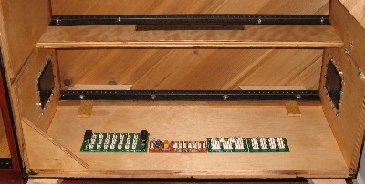
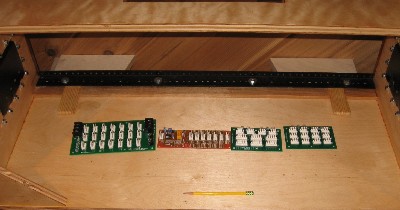
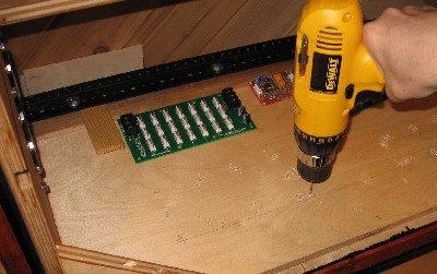
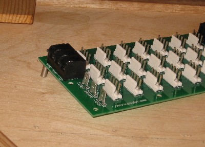
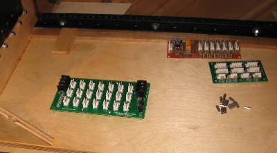
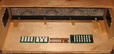
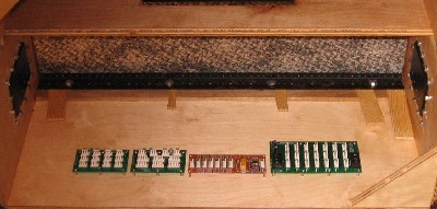
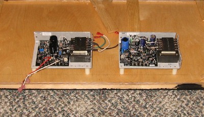
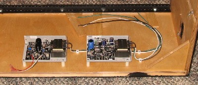
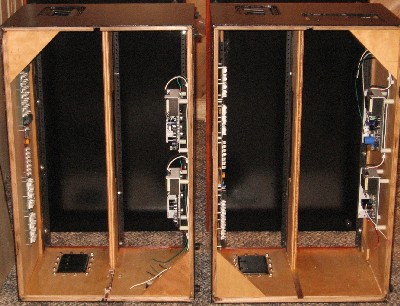
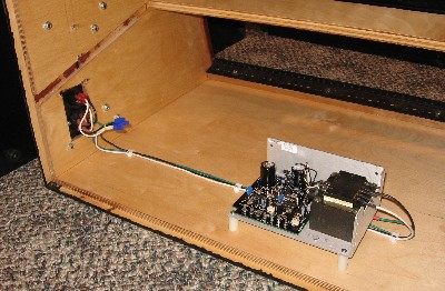
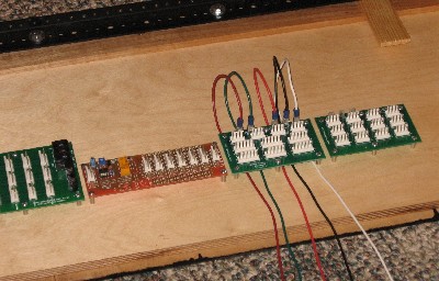
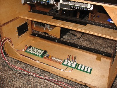
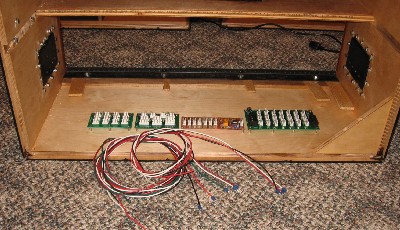
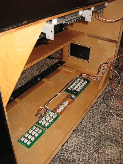
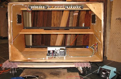
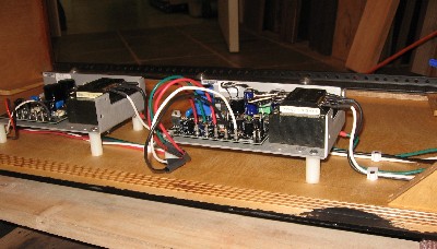
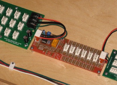
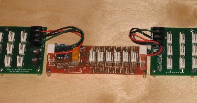
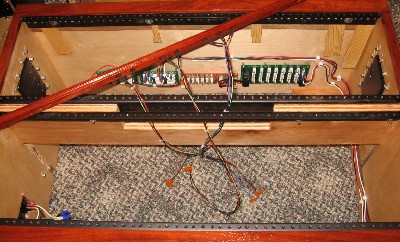
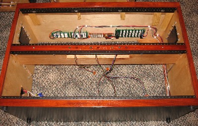
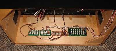
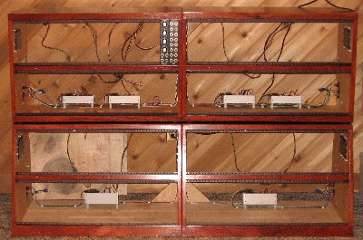
OK - the cabinets built, it's time to empower them. Distribution BoardsWe attached the distribution boards to the tops of the cabinets. Starting with the upper two cabinets— here's how we layed out the distribution boards. Upper-right cabinet first:
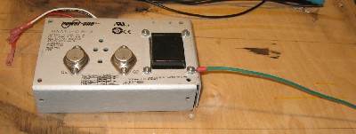
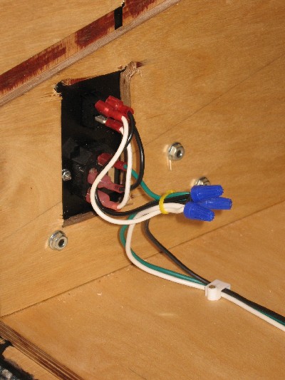
top left layout is the opposite - there's a slight advantage in this because of the location of the modules that need the +5V. In the case of the bottom cabinets, the layout is simpler - it's shown later on this page The Power-OnesThey were connected to the AC power using the switch/plug/power-panels we got from Synth Tech and incorporated into our case designs.
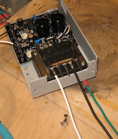
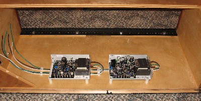
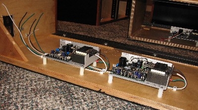
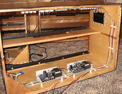
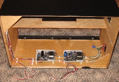
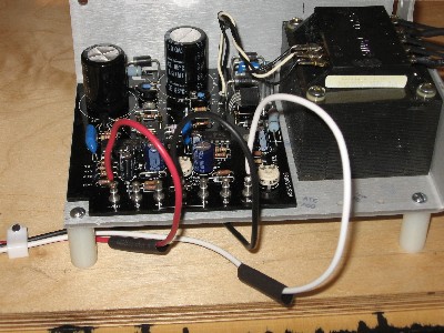
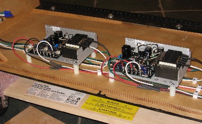
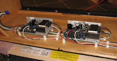
The upper cabinets:We mounted the power-ones so their calibration variable resistors are accessible from the rear of the cabinet
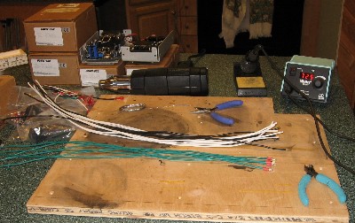
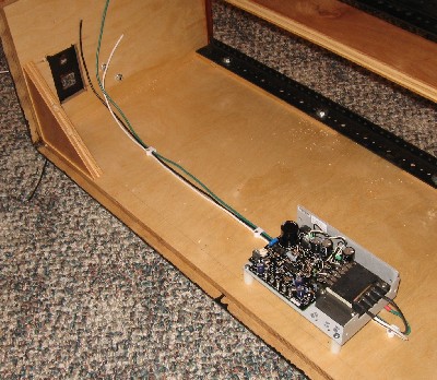
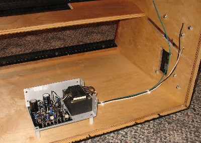
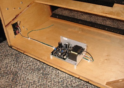
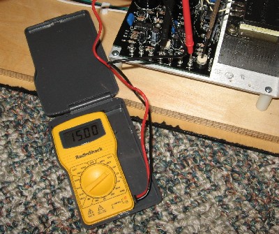
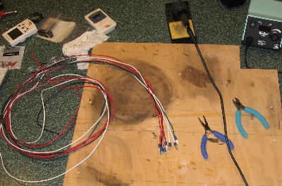
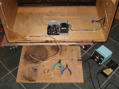
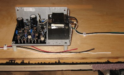
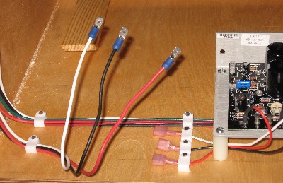
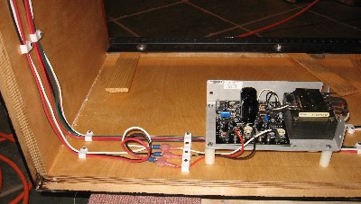
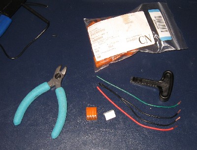
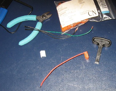
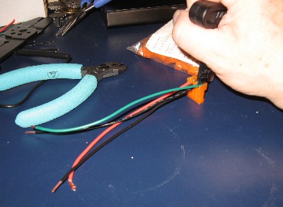
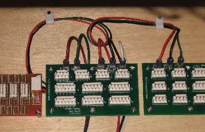
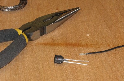
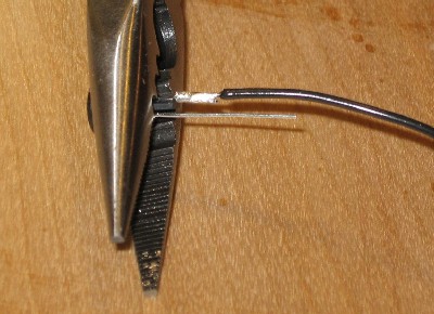
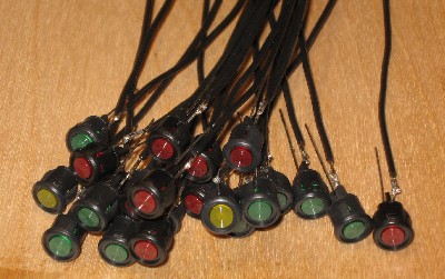
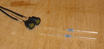
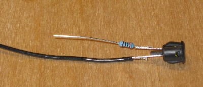
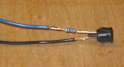
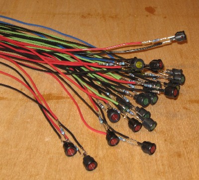
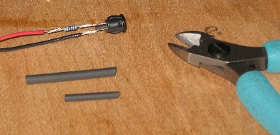
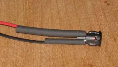
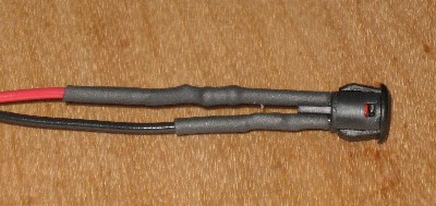
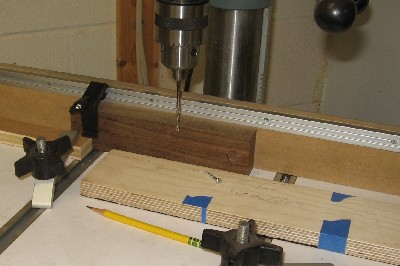
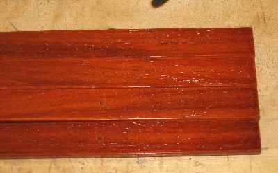
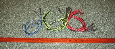
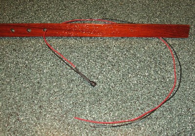
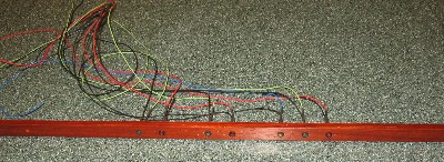
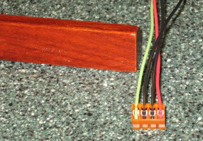
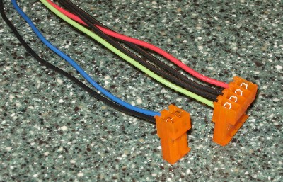
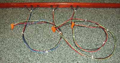
Here's what they look like with the power-ones and distribution panels The bottom cabinets:We connected the power-ones to the AC power using wire-nuts. We adjusted the voltage to satisfy ourselves we'd done it all correctly. Worked like a charm. Distribution WiringWe soldered pan connectors to distribution wires Then starting with the upper cabinets, we ran the distribution wires from the distribution boards to the power-ones — first the upper-right one. We ran the distribution wires around the side of the cabinet opposite the AC power panel and we figured it out so none of the wires had to cross each other in the process. Then the top-left cabinet Connecting the Power OnesThe distribution wires get soldered to the power ones. First, a bottom cabinet. The top cabinets have the two power ones. One of the power ones was used in a stock MOTM 900. Rather than unsolder the connections, we soldered on pan connectors to do the job. Jumper cables for the power delaysWe made little cables to connect the poser delays in line Power indicator LEDsThen we prepared the LEDs with resistors in line pre our diagram (far) above. We cut the wires to 28 in. The LEDs went into the cabinets' center facings.First we drilled holes for the screws that would attach the facings to the cabinets. The we threaded the LED wires through the indicator holes in the facings. We attached plugs to the LED wires And bound them together with ties. We put the facings in place - threading the bound LED wires around the brace like we had planned. And we plugged them in. Done.Some of the LEDs didn't light when we tested them, but we fiddled with the plugs and found loose connections. In the end, all the power ones, the power delays, and the LED indicators worked great! |
|||||||||||||||||||||||||||||||||||||||||||||||||||||||||||||||||||||||||||||||||||||||||||||||||||||||||||||||||||||||||||||||||||||||||||||||||||||||||||||||||||||||||||||||||||||||||||||||||||||||||||||||||||||||||||||||||||||||||||||||||||||||||||||||||||||||||||||||||||||||||||||||||||||||||||||||||||||||||||||||||||||||||||||||||||||||||||||||||||||||||||||||||||||||||||||||||||||||||||||||||||||||||||||||||||||||||||||||||||||||||||||||||||||||||||||||||||||||||||||||||||
Set up / Testing |
|||||||||||||||||||||||||||||||||||||||||||||||||||||||||||||||||||||||||||||||||||||||||||||||||||||||||||||||||||||||||||||||||||||||||||||||||||||||||||||||||||||||||||||||||||||||||||||||||||||||||||||||||||||||||||||||||||||||||||||||||||||||||||||||||||||||||||||||||||||||||||||||||||||||||||||||||||||||||||||||||||||||||||||||||||||||||||||||||||||||||||||||||||||||||||||||||||||||||||||||||||||||||||||||||||||||||||||||||||||||||||||||||||||||||||||||||||||||||||||||||||
Use Notes |
|||||||||||||||||||||||||||||||||||||||||||||||||||||||||||||||||||||||||||||||||||||||||||||||||||||||||||||||||||||||||||||||||||||||||||||||||||||||||||||||||||||||||||||||||||||||||||||||||||||||||||||||||||||||||||||||||||||||||||||||||||||||||||||||||||||||||||||||||||||||||||||||||||||||||||||||||||||||||||||||||||||||||||||||||||||||||||||||||||||||||||||||||||||||||||||||||||||||||||||||||||||||||||||||||||||||||||||||||||||||||||||||||||||||||||||||||||||||||||||||||||
|
|
|||||||||||||||||||||||||||||||||||||||||||||||||||||||||||||||||||||||||||||||||||||||||||||||||||||||||||||||||||||||||||||||||||||||||||||||||||||||||||||||||||||||||||||||||||||||||||||||||||||||||||||||||||||||||||||||||||||||||||||||||||||||||||||||||||||||||||||||||||||||||||||||||||||||||||||||||||||||||||||||||||||||||||||||||||||||||||||||||||||||||||||||||||||||||||||||||||||||||||||||||||||||||||||||||||||||||||||||||||||||||||||||||||||||||||||||||||||||||||||||||||
|
The fine Print: Use this site at your own risk. We are self-proclaimed idiots and any use of this site and any materials presented herein should be taken with a grain of Kosher salt. If the info is useful - more's the better. Bill and Will © 2005-2011 all frilling rights reserved
|
