Bill and Will's Synth
|
||||||||||||||||||||||||||||||||||||||||||||||||||||||||||||||||||||||||||||||||||||||||||||||||||||||||||||||||||||||||||||||||||||||||||||||||||||||||||||||||||||||||||||||||||||||||||||||||||||||||||||||||||||||||||||||||
|
Table of Contents |
||||||||||||||||||||||||||||||||||||||||||||||||||||||||||||||||||||||||||||||||||||||||||||||||||||||||||||||||||||||||||||||||||||||||||||||||||||||||||||||||||||||||||||||||||||||||||||||||||||||||||||||||||||||||||||||||
|
This page has become really long, so here's a table of contents that we hope will make it easier to traverse: Background - presents an explanation and Yves' initial description of the Module Modifications - Yves' modification to the CV input for MOTM users Parts - presents a Bill of Materials and notes about it Panel - presents the MOTM format panel Construction Phase 1 - Resistors, Capacitors, IC Sockets, Power Plugs, MTA headers Construction Phase 2 - Trimmers, Panel connections |
||||||||||||||||||||||||||||||||||||||||||||||||||||||||||||||||||||||||||||||||||||||||||||||||||||||||||||||||||||||||||||||||||||||||||||||||||||||||||||||||||||||||||||||||||||||||||||||||||||||||||||||||||||||||||||||||
Background - Yves' Design |
||||||||||||||||||||||||||||||||||||||||||||||||||||||||||||||||||||||||||||||||||||||||||||||||||||||||||||||||||||||||||||||||||||||||||||||||||||||||||||||||||||||||||||||||||||||||||||||||||||||||||||||||||||||||||||||||
|
Here's Yves' Schematic (click here to download a larger version): Here's what he says about the module: "Well, here is another classical and very special filter based on the EMS diode ladder filter! This filter has a sound of its own and is the signature of the classical Pink Floyd's song 'On the run'. "My aim here was to design a quite faithful copy of this mythic filter while using components that minimize the burden of selecting a great number of matched transistors. This is why I used transistor arrays (CA3046, CA3096). However, because the CA3096 has become a rare part and is now overpriced, I have also designed a PCB with discrete trannies to replace it. As for all the other filters of my YUSYNTH project, I have added an input and an output buffer to adapt this filter to the input and output levels of my modular system. "I also added an input for voltage control of the resonance : everything was there in the original module but was not made available, probably because of the limited size of the patch pin matrix of the AKS/VCS3... "Because, my power supply standard is +15/-15V, I have included a power regulator IC (78L12) to convert +15V to +12V and a single transitor voltage regulator -15V to -9V (I wanted to use a 79L09 but changed my mind when I realized that this voltage regulator is quite a rare part and is difficult to source)." In his design of the circuit, Yves provides two PCB designs - one that uses a CA3096 and one that uses four discrete transistors (two BC557s and two BC547). The CA3096 is very, very difficult to get hold of. We did find some on Ebay in Dec '09 - but not from anyone we'd dealt with. You might substitute a CA3086 available from Bridechamber, nonetheless, when Scott Deyo produced PCBs for the module, he chose the "Discreet Transistor" version to avoid the issue. It's the transistors that replace the CA3096 that should, optimally, be matched - although Yves wrote to us that transistors from the same "batch" will most likely be matched close enough. Here's the layout of his PCB (this is Yves' illustration - thanks, Yves): And here's how it gets wired up (again, this is Yves' illustration): There's more info on his site. But this is going to be a pretty straight-forward thing to do. We're just building it as Yves designed it. |
||||||||||||||||||||||||||||||||||||||||||||||||||||||||||||||||||||||||||||||||||||||||||||||||||||||||||||||||||||||||||||||||||||||||||||||||||||||||||||||||||||||||||||||||||||||||||||||||||||||||||||||||||||||||||||||||
Modifications |
||||||||||||||||||||||||||||||||||||||||||||||||||||||||||||||||||||||||||||||||||||||||||||||||||||||||||||||||||||||||||||||||||||||||||||||||||||||||||||||||||||||||||||||||||||||||||||||||||||||||||||||||||||||||||||||||
|
We ran into a note on electromusic.com regarding changing the input resistor for the control voltage - so we asked Yves about it. He wrote us back: "...if you are using the MOTM or Synthesizers.com ADSR it is better to change R15 to 47K in order to benefit of a wider range. The actual value of R15 was selected having in mind that it would be used with the yusynth envelopes which deliver a 10V ADSR signal while the MOTM envelopes are limited to 5V. I chose 10V for my envelopes because I thought that using V/Oct modules (filters ...) it was logical to have envelopes covering a 10 octave range." So we looked at the schematics - R15 is off of pad "CV 3" on the PCB. We discovered this after we'd already finished Phase 1 of the build so we had to remove the 100K resistor and replace it with the 47K. |
||||||||||||||||||||||||||||||||||||||||||||||||||||||||||||||||||||||||||||||||||||||||||||||||||||||||||||||||||||||||||||||||||||||||||||||||||||||||||||||||||||||||||||||||||||||||||||||||||||||||||||||||||||||||||||||||
Parts |
||||||||||||||||||||||||||||||||||||||||||||||||||||||||||||||||||||||||||||||||||||||||||||||||||||||||||||||||||||||||||||||||||||||||||||||||||||||||||||||||||||||||||||||||||||||||||||||||||||||||||||||||||||||||||||||||
|
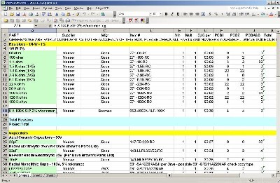
Will and I have developed a parts-list / bill-of-materials in the form of an XL spreadsheet (as usual). After some scrounging, we found everything OK. Please don't take it as gospel. Even so, just now we've used it to make our Mouser and Digikey purchases and we are relatively confident in our specifications. The module requires "matched diodes" and the transistors that replace the CA3096 should, again, optimally, be matched. Now again, Yves wrote to us that transistors from the same "batch" will most likely be matched close enough, but we wanted to learn how to match transistors anyway... so we did some research, built a little tester circuit, and went about matching some transistors - we used some that were within 2mV of each other. The diodes were easier - we just used our new test meter that has a diode tester to measure them. Per Yves's parts list, we used diodes within 3mV of each other. Click here to download our XL spreadsheet Parts List |
||||||||||||||||||||||||||||||||||||||||||||||||||||||||||||||||||||||||||||||||||||||||||||||||||||||||||||||||||||||||||||||||||||||||||||||||||||||||||||||||||||||||||||||||||||||||||||||||||||||||||||||||||||||||||||||||
|
Panel |
||||||||||||||||||||||||||||||||||||||||||||||||||||||||||||||||||||||||||||||||||||||||||||||||||||||||||||||||||||||||||||||||||||||||||||||||||||||||||||||||||||||||||||||||||||||||||||||||||||||||||||||||||||||||||||||||
|
We got ours from Bridechamber: The paint had made the holes a little too small - no biggie just a couple twists of our rat-tail file and all is well. |
||||||||||||||||||||||||||||||||||||||||||||||||||||||||||||||||||||||||||||||||||||||||||||||||||||||||||||||||||||||||||||||||||||||||||||||||||||||||||||||||||||||||||||||||||||||||||||||||||||||||||||||||||||||||||||||||
Construction Phase 1All the stuff in Phase 1 gets soldered using "Organic" Solder. At every break in the action, we wash the board off to get rid of the flux. |
||||||||||||||||||||||||||||||||||||||||||||||||||||||||||||||||||||||||||||||||||||||||||||||||||||||||||||||||||||||||||||||||||||||||||||||||||||||||||||||||||||||||||||||||||||||||||||||||||||||||||||||||||||||||||||||||
|
Jumpers, Resistors, Capacitors, Power |
||||||||||||||||||||||||||||||||||||||||||||||||||||||||||||||||||||||||||||||||||||||||||||||||||||||||||||||||||||||||||||||||||||||||||||||||||||||||||||||||||||||||||||||||||||||||||||||||||||||||||||||||||||||||||||||||
|
We're combining all these components in one photo. It's pretty self evident. As usual, whereas we are vigilant about orienting all the resistors, caps, etc. consistently so their values can be read easily (in case we need to trouble-shoot them later), we oriented the resistors with the "tolerance" stripe on the left (relative to the text on the pcb). We got started doing it this way when we started building our synth and now we do it so all our modules are consistent with each other. You might want to do it the opposite way - with the "tolerance" stripe on the right. Also of note is the jumper that will be under the CA3046 IC. We made sure this was squished down flat against the PCB to take up as little space as possible. Later on, we discovered the modification of replacing R15 with 47K. If you're going to use an Oakley, synthesizers.com, or MOTM ADSR you should do this right off the bat. |
||||||||||||||||||||||||||||||||||||||||||||||||||||||||||||||||||||||||||||||||||||||||||||||||||||||||||||||||||||||||||||||||||||||||||||||||||||||||||||||||||||||||||||||||||||||||||||||||||||||||||||||||||||||||||||||||
|
ICs - Misc Stuff |
So far so good. Our progress got stalled for a few months until we could get around to matching diodes and transistors. We had bought 100 1N4148 diodes and we measured them with our Digital Volt Meter's diode tester setting. Per Yves, we needed 14 diodes matched within 3 milliVolts. We wound up with more than 14 that measured 635 - so we used them. We also bought 100 BC557s and 100 BC547s and measured them per the MOOG Transistor Matching Technique. Per Yves, we optimally needed two of each matched transistors in place of the CA3096 IC. Among many matches we had, we wound up with three of each that measured 592 milliVolts. We used those. |
|||||||||||||||||||||||||||||||||||||||||||||||||||||||||||||||||||||||||||||||||||||||||||||||||||||||||||||||||||||||||||||||||||||||||||||||||||||||||||||||||||||||||||||||||||||||||||||||||||||||||||||||||||||||||||||||
|
Changing R15 |
Now, you won't have to do this, but we didn't know about the R15 mod up front, so we changed it from 100K to 47K here.
|
|||||||||||||||||||||||||||||||||||||||||||||||||||||||||||||||||||||||||||||||||||||||||||||||||||||||||||||||||||||||||||||||||||||||||||||||||||||||||||||||||||||||||||||||||||||||||||||||||||||||||||||||||||||||||||||||
|
|
||||||||||||||||||||||||||||||||||||||||||||||||||||||||||||||||||||||||||||||||||||||||||||||||||||||||||||||||||||||||||||||||||||||||||||||||||||||||||||||||||||||||||||||||||||||||||||||||||||||||||||||||||||||||||||||||
Construction Phase 2All the stuff in Phase 2 gets soldered using "No-Clean" Solder and the PCB doesn't get washed off from here on. |
||||||||||||||||||||||||||||||||||||||||||||||||||||||||||||||||||||||||||||||||||||||||||||||||||||||||||||||||||||||||||||||||||||||||||||||||||||||||||||||||||||||||||||||||||||||||||||||||||||||||||||||||||||||||||||||||
|
Trimmers |
||||||||||||||||||||||||||||||||||||||||||||||||||||||||||||||||||||||||||||||||||||||||||||||||||||||||||||||||||||||||||||||||||||||||||||||||||||||||||||||||||||||||||||||||||||||||||||||||||||||||||||||||||||||||||||||||
|
PCB / Panel connections |
||||||||||||||||||||||||||||||||||||||||||||||||||||||||||||||||||||||||||||||||||||||||||||||||||||||||||||||||||||||||||||||||||||||||||||||||||||||||||||||||||||||||||||||||||||||||||||||||||||||||||||||||||||||||||||||||
|
We worked out this chart for the module's connection wiring.
Using the above table, we determined that of the above wires, connections 1., 3., 4., 6., 7., 9., 12., 15, 18., 19., 20., and 24 are to the PCB. So we made a chart of those in a good soldering order to make it easy to refer to and we soldered them into the PCB before mounting it.
| ||||||||||||||||||||||||||||||||||||||||||||||||||||||||||||||||||||||||||||||||||||||||||||||||||||||||||||||||||||||||||||||||||||||||||||||||||||||||||||||||||||||||||||||||||||||||||||||||||||||||||||||||||||||||||||||||
|
ICs into Sockets |
||||||||||||||||||||||||||||||||||||||||||||||||||||||||||||||||||||||||||||||||||||||||||||||||||||||||||||||||||||||||||||||||||||||||||||||||||||||||||||||||||||||||||||||||||||||||||||||||||||||||||||||||||||||||||||||||
|
Mounting Bracket |
||||||||||||||||||||||||||||||||||||||||||||||||||||||||||||||||||||||||||||||||||||||||||||||||||||||||||||||||||||||||||||||||||||||||||||||||||||||||||||||||||||||||||||||||||||||||||||||||||||||||||||||||||||||||||||||||
|
We drilled holes into the mounting bracket for the PCB. We used 1/4in spaces and 8-32 screws (the PCB accommodates #8 screws). |
||||||||||||||||||||||||||||||||||||||||||||||||||||||||||||||||||||||||||||||||||||||||||||||||||||||||||||||||||||||||||||||||||||||||||||||||||||||||||||||||||||||||||||||||||||||||||||||||||||||||||||||||||||||||||||||||
|
Mounting the PCB |
||||||||||||||||||||||||||||||||||||||||||||||||||||||||||||||||||||||||||||||||||||||||||||||||||||||||||||||||||||||||||||||||||||||||||||||||||||||||||||||||||||||||||||||||||||||||||||||||||||||||||||||||||||||||||||||||
|
Because we want to mount the PCB behind the panel like we do for all our other modules - on the right - and also we want the PCB to have the power header at the back with the -15 pin on top, we're mounting it upside-down. |
||||||||||||||||||||||||||||||||||||||||||||||||||||||||||||||||||||||||||||||||||||||||||||||||||||||||||||||||||||||||||||||||||||||||||||||||||||||||||||||||||||||||||||||||||||||||||||||||||||||||||||||||||||||||||||||||
|
Pots / Chicklets |
||||||||||||||||||||||||||||||||||||||||||||||||||||||||||||||||||||||||||||||||||||||||||||||||||||||||||||||||||||||||||||||||||||||||||||||||||||||||||||||||||||||||||||||||||||||||||||||||||||||||||||||||||||||||||||||||
|
We'll fix up the 10K linear and 50K log pots we got with Chicklets (from John Loffink). The 25K pots are round ones - we'll wire directly to their lugs. | ||||||||||||||||||||||||||||||||||||||||||||||||||||||||||||||||||||||||||||||||||||||||||||||||||||||||||||||||||||||||||||||||||||||||||||||||||||||||||||||||||||||||||||||||||||||||||||||||||||||||||||||||||||||||||||||||
|
The Pots and Jacks |
||||||||||||||||||||||||||||||||||||||||||||||||||||||||||||||||||||||||||||||||||||||||||||||||||||||||||||||||||||||||||||||||||||||||||||||||||||||||||||||||||||||||||||||||||||||||||||||||||||||||||||||||||||||||||||||||
|
The Resonance, Frequency CV, and Resonance CV pots hold the mounting bracket to the panel.
|
||||||||||||||||||||||||||||||||||||||||||||||||||||||||||||||||||||||||||||||||||||||||||||||||||||||||||||||||||||||||||||||||||||||||||||||||||||||||||||||||||||||||||||||||||||||||||||||||||||||||||||||||||||||||||||||||
|
Making the Connections |
||||||||||||||||||||||||||||||||||||||||||||||||||||||||||||||||||||||||||||||||||||||||||||||||||||||||||||||||||||||||||||||||||||||||||||||||||||||||||||||||||||||||||||||||||||||||||||||||||||||||||||||||||||||||||||||||
|
OK - step by step: 1. Resonance Pot - 10K lin 2. Frequency Pot - 10K lin 3. Frequency CV Pot - 25K lin
4. Input 1 Pot - 50K log 5. Resonance CV Pot - 25K lin
6. Input 2 Pot - 50K log 7. Output Jack 8. Resonance CV Jack 9. Frequency CV Jack 10. 1V/Oct Jack 11. Input 2 Jack 12. Input 1 Jack Jacks |
||||||||||||||||||||||||||||||||||||||||||||||||||||||||||||||||||||||||||||||||||||||||||||||||||||||||||||||||||||||||||||||||||||||||||||||||||||||||||||||||||||||||||||||||||||||||||||||||||||||||||||||||||||||||||||||||
|
Ties |
||||||||||||||||||||||||||||||||||||||||||||||||||||||||||||||||||||||||||||||||||||||||||||||||||||||||||||||||||||||||||||||||||||||||||||||||||||||||||||||||||||||||||||||||||||||||||||||||||||||||||||||||||||||||||||||||
|
Knobs |
||||||||||||||||||||||||||||||||||||||||||||||||||||||||||||||||||||||||||||||||||||||||||||||||||||||||||||||||||||||||||||||||||||||||||||||||||||||||||||||||||||||||||||||||||||||||||||||||||||||||||||||||||||||||||||||||
|
Construction Done |
||||||||||||||||||||||||||||||||||||||||||||||||||||||||||||||||||||||||||||||||||||||||||||||||||||||||||||||||||||||||||||||||||||||||||||||||||||||||||||||||||||||||||||||||||||||||||||||||||||||||||||||||||||||||||||||||
|
Set up / Testing |
||||||||||||||||||||||||||||||||||||||||||||||||||||||||||||||||||||||||||||||||||||||||||||||||||||||||||||||||||||||||||||||||||||||||||||||||||||||||||||||||||||||||||||||||||||||||||||||||||||||||||||||||||||||||||||||||
|
Use Notes |
||||||||||||||||||||||||||||||||||||||||||||||||||||||||||||||||||||||||||||||||||||||||||||||||||||||||||||||||||||||||||||||||||||||||||||||||||||||||||||||||||||||||||||||||||||||||||||||||||||||||||||||||||||||||||||||||
|
|
||||||||||||||||||||||||||||||||||||||||||||||||||||||||||||||||||||||||||||||||||||||||||||||||||||||||||||||||||||||||||||||||||||||||||||||||||||||||||||||||||||||||||||||||||||||||||||||||||||||||||||||||||||||||||||||||
|
The fine Print: Use this site at your own risk. We are self-proclaimed idiots and any use of this site and any materials presented herein should be taken with a grain of Kosher salt. If the info is useful - more's the better. Bill and Will © 2005-2011 all frilling rights reserved
|


