Bill and Will's Synth
|
||
Table of Contents |
||
|
This page has become really long, so here's a table of contents that we hope will make it easier to traverse: Background - presents an explanation and Ken Stone's initial description of the Module with his photos Parts - presents a Bill of Materials and notes about it Panel - presents the MOTM format panel Construction Phase 1 - Resistors, Capacitors, IC Sockets, Power Plugs, MTA headers Construction Phase 2 - Trimmers, Tube, Panel connetcions |
||
Background - Ken Stone's Design |
||
|
Ken presents two versions of the Real Ring Modulator - one without any active components (the "Real Ring Modulator") and one with input and output buffer/amplifiers (the "Active Real Ring Modulator"). In both cases, the core ring modulator part is the same and here's what Ken says about it on his site: "Four quadrant multipliers have more or less replaced ring modulators in synthesizers, even though they still bear the label "ring modulator". The distortion in these is lower than that of a true diode ring modulator, because the diode voltage drops have been eliminated. This leads to better specifications, though in a noise maker, this is not always desirable. "For years I have been building various four quadrant modulators, and have been satisfied with none of them. Not one of them had the raw sonic beauty of the traditional ring modulators I made when I was first starting out in synthesizer building. "For that reason I present here the "Real Ring Modulator", a traditional diode and transformer ring modulator. Each is hand assembled using matched germanium diodes and a pair of brand new 3k impedance transformers. Some RRMs used diodes from a computer from 1969, but due to the huge demand for these modulators, I have used up my stocks and may now use brand new germanium diodes as needed. The sound remains the same."
Ken writes this about his "Active Real Ring Modulator": "Here is an updated version of the popular "Real Ring Modulator", a traditional diode and transformer ring modulator. This time, a preamplifier for external input, and input and output buffers for conventional synthesizer levels are included." Here's Ken's Schematic (click here to download a larger version): Here's the overlay of the PCB: Here's his photo of the finished PCB: And here's Ken's layout and wiring diagram of the PCB: This note from Ken: "The pad labelled "0V" on the REV0.0 and VER1.0 versions of the CGS67 is actually connected to the -VE rail. You will need to connect to 0V elsewhere on the board. The pad in question was previously shown as the common 0V connection in the wiring diagram." There's more info on Ken's site. and in the discussion in the Electro-Music forum. |
||
Parts |
||
|
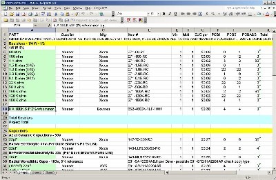
Will and I have developed a parts-list / bill-of-materials in the form of an XL spreadsheet (as usual). After some scrounging, we found everything OK. Please don't take it as gospel. Even so, just now we've used it to make our Mouser and Digikey purchases and we are relatively confident in our specifications. Click here to download our XL spreadsheet Parts List |
||
Panel |
||
|
We got ours from Bridechamber: |
||
Construction Phase 1All the stuff in Phase 1 gets soldered using "Organic" Solder. At every break in the action, we wash the board off to get rid of the flux. |
||
Construction Phase 2All the stuff in Phase 2 gets soldered using "No-Clean" Solder and the PCB doesn't get washed off from here on. |
||
Set up / Testing |
||
Use Notes |
||
|
|
||
|
The fine Print: Use this site at your own risk. We are self-proclaimed idiots and any use of this site and any materials presented herein should be taken with a grain of Kosher salt. If the info is useful - more's the better. Bill and Will © 2005-2011 all frilling rights reserved
|


