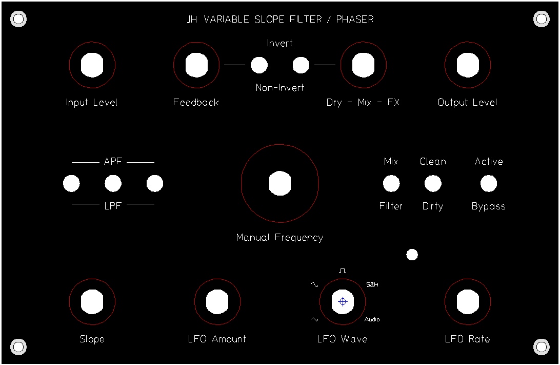
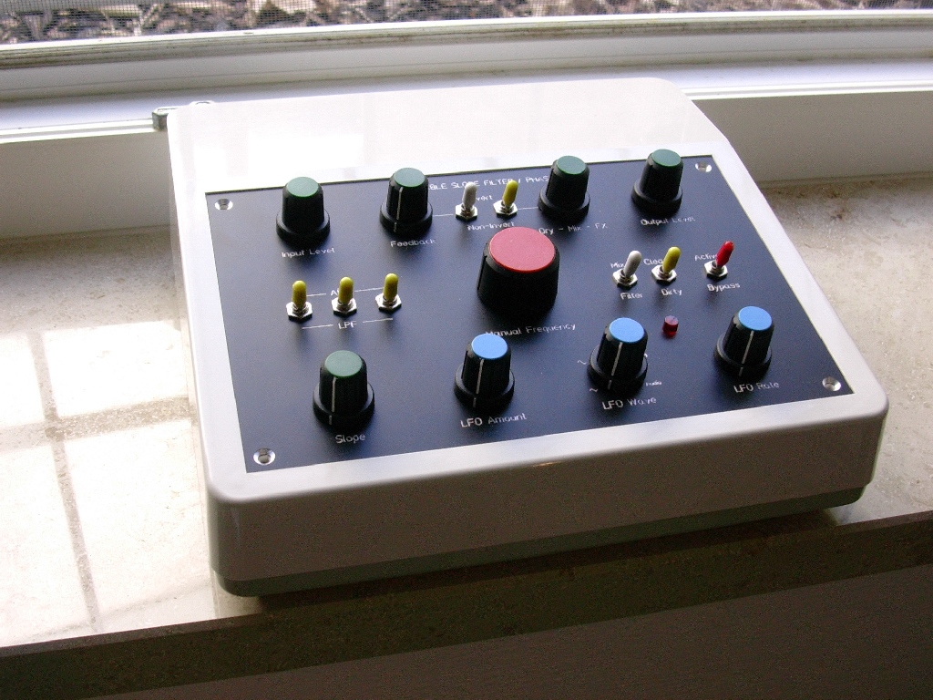
"Variable Slope Filter / Phaser "
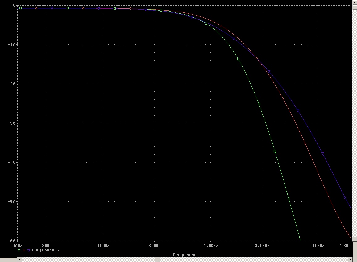
- Powerfull 36dB/Oct LPF (6-pole Filter)
- Variable Filter Slope (voltage controlled)
- Resonance
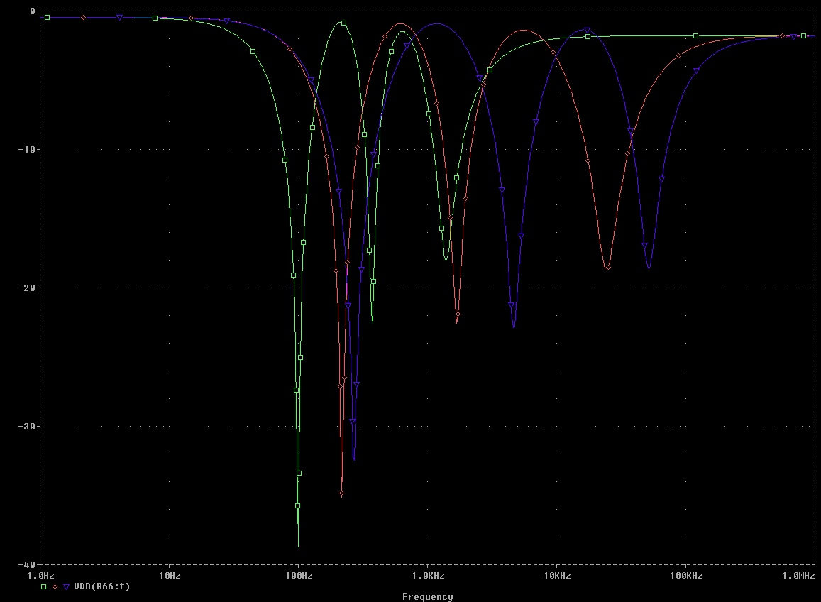
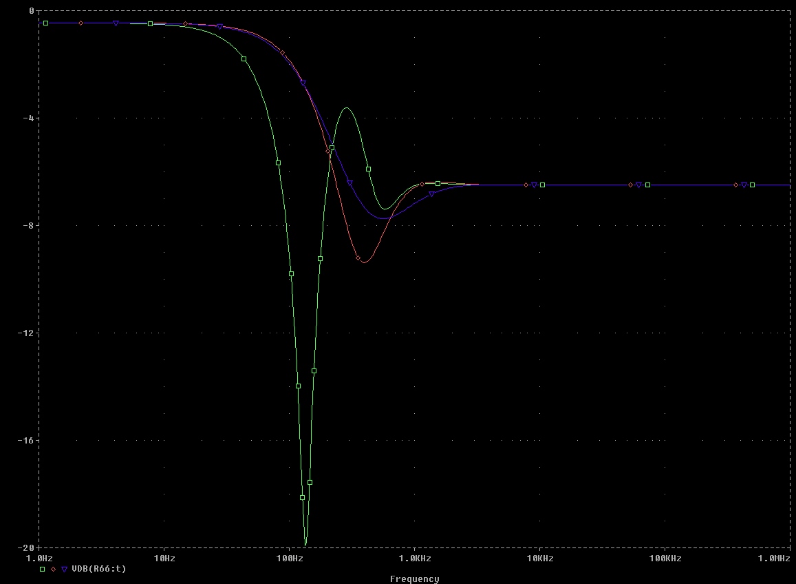
- Phaser with equal poles, or spread poles (voltage controlled)
- "Everything between filter and phaser" (combination of APF and LPF stages)
- Unique on-board LFO with volzage controlled waveform-crossfading
- Audio-Rate and Random Sample & Hold Modulation
- Standalone FX (with 16V AC wallwart) or +/-15V Synthesizer Module
- No need to implement everything - omit half the components and still have the 36dB/Oct LPF ...
back to JH. homepage