JH. String Filter
Back to JH. Homepage
History:
In 2004, I built a String Filter - I even made a PCB layout for this,
which was untypical for me at the time. (Built most of my stuff on
veroboard back then.)
I liked it a lot, and I got a lot of positive feedback for the sound demos.
Unfortunately, the filter topology, a variant of the GIC filter and
probably my own invention turned out to be a failure: It worked, but I
only got it to work stable with NE5532 chips of a certain date code.
Hardly something I could publish for other DIY'ers to build.
Now, I've started that project all over again, with a different filter topology.
Also very different from the classic Electronotes single-opamp filters
(and as far as I can tell, also from Moog's string filter), I'm now
going for a two-opamp biquad topology. This generally not so well-known
filter uses two integrators like the ubiquitous 3-opamp state variable
and biquad filters, but unlike these, one of the integrators is
non-inverting: The so-called Deboo-Integrator.
But before I describe the new project, which will also be awailable as
PCBs (if everything work as intended, this time!), I insert the
information of my old string filter project here:
Credits:
This was inspired by
Ian Fritz, "Filter Bank Design", Electronotes EN#107,
Bernie Hutchins, "A 39-Channel Variable Q Filter Bank", EN#115,
Arthur Benade, "Fundamentals of Musical Acoustics" 2nd edition 1990,
and
Kenneth Elhardts fascinating string sounds
A string filter has been on my personal wish list for a long time. The
above mentioned Electronotes articles give a good description what is possible
with multiple resonances, and also describe a feedback method to control
depth of the peaks and notches, starting with filters of fixed Q. And there
is the legendary (and rare) Moog CE String Filter that is based on a similar
principle.
The Moog filter uses Norton Amplifiers, Ian has used discrete transistor
circuits, Bernie has used Deliyannis filters with opamps.
My version is based on LC resonators, where the inductors are replaced
with 2 opamp, 4 resistor General Impedance Converters. The advantage of
this is that there are only 4 equal resistors, two equal capacitors, and
one dual opamp needed per partial filter, and that there are no trimpots
required - the downside is that the capacitors must be selected.
I've made a stereo version, where even filter numbers go to one output,
and odd filter outputs go to a second output. A "separation" potentiometer
allows everything from Mono to extreme Stereo panning. It turned out that
just a _slight_ amount of "separation" gives some pleasant room information
without messing up the impression of a single sound source.
In addition to this 40-band Filter Bank, I'm using some parametric filters
to emulate the Main Wood Resonance, Main Air Resonance, and Bridge Resonance
of various sized string instruments. I plan to make an individual filter
for Cello, Viola (Bratsche) and Violin, based on the plots in Benade's
book. Unfortunately, Benade doesn't give detailed dB levels for his courves,
so I have to try different gain and Q factors. So far, I have finished
the Cello Filter. (which still needs some fine tuning of the Q's and gain
factors, no doubt! Also have to find the right width of the Notch around
1.5 kHz for the Cello.) Viola and Violin will be next.
I don't expect to get the sound of real string instruments (this needs
some physical modeling of the bow/string system at least!) , but I want
to gain some "organic" quality for otherwise electronic sounds.
sample
1: CS-50 dry and thru Cello Filter
CS-50 with typical electronic string sound: saw wave, filter quite open,
some vibrato and level boost via aftertouch. First dry, then run thru a
set of four parametric filters (Wood resonance, air resonance, bridge resonance,
bridge notch) and thru the 40-band GIC filter bank. (Sorry for the hum
- this was a quick and dirty recording and I have caught a bad GND loop.)
sample
2: OB-8, GIC filter bank with variable feedback
Not related to string instruments. A percussive arpeggio from the OB-8,
first dry, then after 11 seconds switched to the 40-band GIC filter. Resonance
gradually increased. First just some warmth added, then quite unnatural
ringing of the filters.
To bee continued. Hints for improoving Q and gain factors welcome. Circuit
to be disclosed later - not quite finished at the moment.
Meanwhile, here are some pictures:
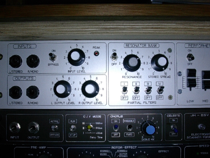
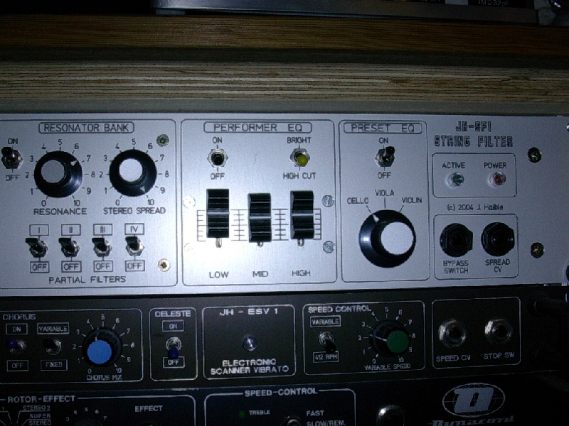
String Filter 2008
The biggest difference, compared to the old string filter, is
that the new one has trimpots. No more measuring and selecting
capacitors.
And the new one has voltage controlled resonance.
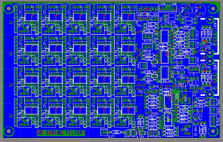
Here's a glimpse of what the new PCBs will look like: (You need two PCBs for a 40-band filter bank)
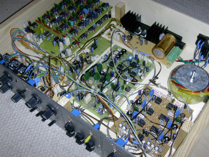
Prototype of String Filter 2008:
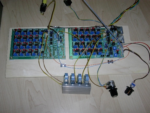
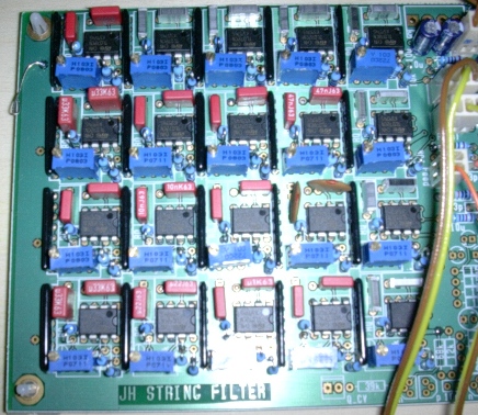
Detail View:
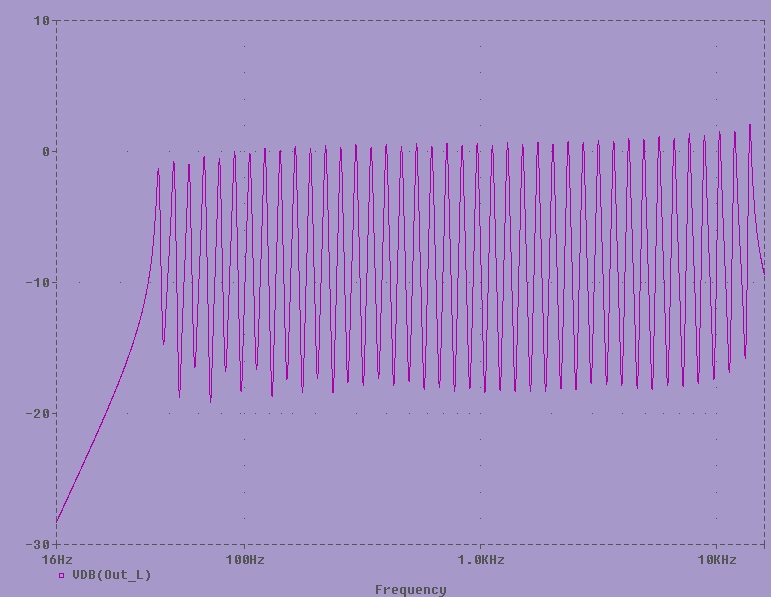
Simulated Frequency Response of 40-Band Filterbank (Board 1 + 2)
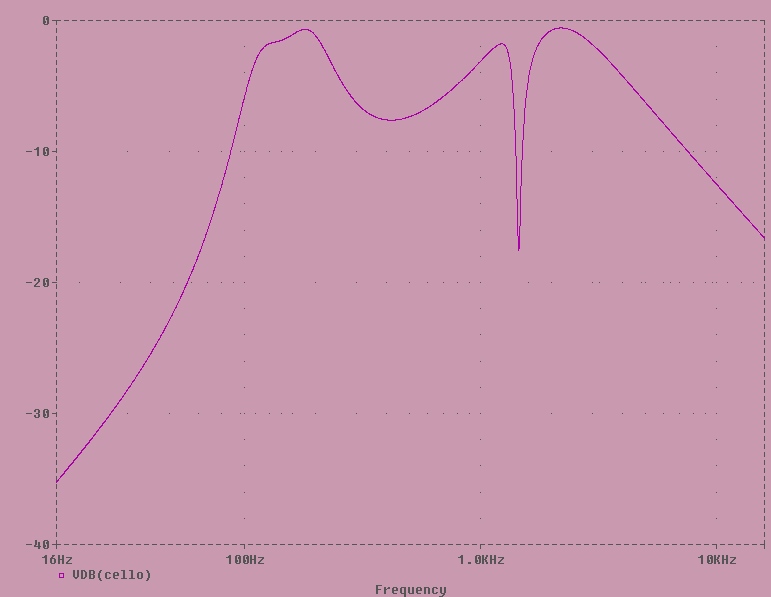
Cello Filter (will be part of a 3rd board, available in the future, together with viola and violin filters)
Filter Bank and Equalisation options
The Filter Bank part creates a lot of equally distributed resonance peaks - this
is responsibel for the "woody" character:
That's the part that is common to all string instruments, more or
less.
(Board 1 + 2, what I'm taking preorders for now.)
The resonance control changes the height of the peaks vs. valleys for all
peaks in common.
The Equalisation emulates the frequency response due to body size
(dimensions of the wooden body and volume of air, plus dimensions of the
bridge). This is different for each instrument. The picture here
http://www.jhaible.heim.at/string_filter/cello_filter_plot.jpg shows
the equalisation I'm using for a Cello. This, and similar EQs for other
instruments, will be on Board 3 (not specified yet).
Boards 1 + 2 are designed such that you can also connect 40 potentiometers
to get a fully variable 40-band filterbank. :)
If you do this (40 sliders anybody?), you don't need any extra EQing - you
can simply draw the courves with the slider position.
But I think a 40-slider filterbank is not for the faint of heart ... I just
wanted to mention it. :)
Part of the standard implementation, however: 4 toggle switches to thake
out every fourth resonant peak (or 2 out of 4, or 3 out of 4), for special
effects.
New Sound Samples
Fast OB-8 Arpeggiator transformed with String Filter
String-like OB-8 Sound made more string-like with String Filter
(This is just the 40-band Filterbank in action; no additional Cello-Equalization as in the sample from the old String Filter!)
Short OB-8 arpeggiated strings
1. Dry
2. 40-Band Filterbank and Cello-Filter breadboard circuit
3. Dry
4. 40-Band Filterbank only
Schematics
PCB 1 + PCB 2 Schematics
Components Overlay
Generic Overlay, as silkscreened on the boards
PCB 1, Component Values
PCB 1, Reference Designators
PCB 2 Component Values
PCB 2, Reference Designators
BPF Blocks
The component density in the actual band pass filter blocks is too
high to print all the component values or reference designators
onto the PCB.
But the 40 BPF blocks all have the same layout, so I'm giving a detailed view on one of the blocks in the picturte below:
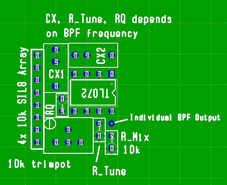
Each BPF block has the following components, regardless of its center frequency:
A Dual OpAmp (TL072 or similar)
An array of 4 individual 10k resistors in a SIP8 package (or, alternatively, 4 vertically mounted 10k 1% metal film resistors)
Another 10k resistor "R_Mix"
A 10k multiturn trimpot
Each BPF block has the following individual components, depending on its center frequency:
Two capacitors CX1 and CX2, both having the same value CX (10% tolerance)
One resistor RQ (located near pin 5 of the OpAmp)
One resistor R_Tune (located near pin 7 of the OpAmp)
PCB 1 and PCB 2 are the same board from the factory - they only differ in which componets you solder in.
Therefore, you only find "CX" etc printed on the board, and the above
component overlay for PCB 1 and PCB 2 are mapped like shown below.
On the left is what you find printed on the board, and on the right is
what you find in the component overlay you can print out from this web
site:
|
|
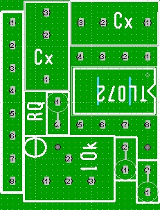
Silkscreened on Board:
Location of RQ
Location of capacitors
SIL array outline only (value always 10k - not shown)
Dual Opamp (TL072 recommended)
Trimpot (always 10k)
R_Mix outline only (always 10k)
|
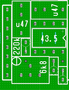
What you can print out separately for PCB 1 and PCB 2:
Center frequency for this filter is 43.5 Hz
(printed in opamp outline; can be measured at Pin 7 of opamp)
RQ value for this individual filter is 220k
CX value for this filter is 0.47 uF (= 470nF)
R_Tune value for thi sfilter is 6k8 (=6.8 kOhm)
(R_Tune value printed in outline of trimpot for lack of space)
|
Is this confusing? It may look so at first glance. But once you have
the boards and the printouts in front of you, it will work like a charm.
(Hint: You won't mix up the trimpot value with the R_tune value once the trimpots are soldered in, and hide the "10k" print.)
Bill Of Materials
BOM
Heat Sink
You may have noticed that the BOM mentions
heatsinks for the LM317 and LM337 voltage regulators, but no particular
heatsink has been specified.
There are footprints on the PCB for the same heatsinks as the Krautrock Phaser, but I do not
recommend using these. Even though I tried them and you can see them in
my prototype phote above. :) They get very hot (depending on the
transformer or wallwart secondary voltage). Because I've expected
something like that, I've placed the voltage regulators at the edge of
the PCB, metal part of the TO220 package facing outward, so you can
easily mount a big heatsink there, and this is what I recommend.
Important: This heatsink must be electrically insulated from the LM317 and LM337.
I won't describe the process of insulated mounting of TO220 packages on
heatsinks in detail here, as it's common practice. (Using thin mica
sheets between the IC and the heatsink.) Just make sure ther is no
electrical contact between the heatsink and the metal part of the
regulators. (Measure it!)
You can get an idea of a possible heatsink construction from this picture (of the Scanner Vibrato). You only need one heatsink for both regulators, but you have to insulate them.
If you have a metal enclosure with a smooth metal surface on the inside, you might be able to just use this as a heatsink. (Also with insulated mounting!)
If you build a +/-15V DC supply version, no heat sink is required, of course. (There are no on-board regulators then.)
Connecting the two boards
Here's how the two PCBs should be connected together.
To be continued ...
JH.
For more information, please contact
Juergen Haible
Copyright J. Haible (C) 2004 - 2008