|
|
 |
|
|
|
|
|
|
Ever since I had designed that Interpolating
Scanner for the JH-3
Synthesizer, I wanted to use it for this very application which had
inspired it in the first place: An emulation of the the Hammond Scanner
Vibrato, without moving parts.
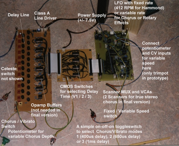
Now I've finally found the time to make some experiments, and I have
built two veroboards, one with a "Line Box", and one with the Scanner.
I did some simulations for option (a). And I found that an electronic
version of this "simple" LC circuit of basically 25 identical L's and C's
is not so simple at all! First of all, a 50-pole LPF is not trivial. The
better of my two filter design programs allows for a maximum filter order
of 25. There are not many applications that need a 300dB/Octave LPF, after
all. (;->) Also, it's not enough to get the desired response at the end
of such a filter. Every tap along the line must carry the right signal,
i. e. delayed by a certain fraction of 1ms, and with a fairly smooth amplitude
response. Both of these constraints cry for a FDNR implementation, where
the topology of the original LC circuit is preserved. Just simulation the
inductors with gyrators is difficult, as all these inductors are floating
(not grounded). So we have to transform inductors to resistors, resistors
to capacitors, and the (grounded) resistors to grounded frequency dependend
negative resisors (FDNRs) a.k.a. "super capacitors". This would certainly
have been possible, but it's an increadible demanding application for the
opamps that are used. TL074's, which are certainly fast enough for ordinary
audio applications, are way too slow for a FDNR LPF with a few kHz cutoff
frequency. This will result in an overshot that is increased from stage
to stage - no way to build a Line Box with 25 stages with these. I could
have used much better opamps, but these would have been expensive, and
fast as they are, a lot of decoupling capacitors would have been needed.
So this solution was discarded, and I chose option (b) instead.
So following option (b), I went shopping for affordable inductors.
I found some unexpensive, small, pcb-mount 33mH inductors.
Some quick calculations were encouraging:
Making an impedance transformation on the original Hammond circuit,
a capacitor value of 47nF would fit for the 33mH inductors,
providing the same 1ms delay and the same cutoff frequency as the original,
and resulting in a decreased line impedance of 840 Ohm.
Now 840 Ohm isn't that low really - it can still be driven from a simple
emitter follower without much effort. I was uncertain about the maximum
current the inductors could carry without distortion, and thus about the
maximum signal voltage that can feed the delay line. I found that a signal
of 4Vpp is no problem. And I didn't intend to go much higher anyway: As
I'm using 4000 series CMOS switches in the scanner, a supply voltage of
+/-7.5V was chosen anyway. So as a nice coincidents, all these factors
fit together.
The remaining question was about the losses in the inductors. These
losses are higher than in the original Hammond circuit. (No surprise when
you look at these tiny inductors!) But Hammond had to take care of these
losses, too. As the signal voltage decreases along the Delay Line, taps
at the beginning of the Line were attenuated by resistors, and taps at
the end of the line were fed into the scanner unattenuated. As the losses
in my curcuit are slightly larger, the compensation for the individual
taps must be different. I have simply fed a signal into the line, measured
the level after each inductor, and calculated a correction factor.
At the moment (verobaord test circuit) each tap (after each inductor)
is buffered with an opamp that compensates the loss. I did this because
I also plan to experiment with multiple scanners scanning alongthe same
delay line (trying to get a solina triple chorus effect). For a final Hammond-Vibrato
version, these opamps can be omitted, and weighted resistor values to feed
the scanner can be used instead. (For the VCAs in the scanner, the signal
is divided down to 20mVpp anyway.)
Schmatics for this Delay Line will come soon. I have to make a clean
drawing first.
Organ with Scanner Vibrato in Chorus 1 (C1) mode (64kB)
Organ with Scanner Vibrato in Chorus 2 (C2) mode (82kB)
Organ with Scanner Vibrato in Chorus 3 (C3) mode (108kB)
Organ with Scanner Vibrato in Vibrato 1 (V1) mode (59kB)
Organ with Scanner Vibrato in Vibrato 2 (V2) mode (65kB)
Organ with Scanner Vibrato in Vibrato 3 (V3) mode (85kB)
Pad sounds from an OB-8 synthesizer thru Scanner Vibrato in C3 mode (1.1MB)