Bill and Will's Synth
|
||||||
|
||||||
|
April 2007 - The MOTM 120 has a "difficulty factor" of 2, but we're going to include the Richard Brewster / Scott Juskiw 120 Daughter Board in our construction so it's probably more difficult. This poses a bit of a challenge because the Stooge Panels aren't readily available at the time of this construction (April, 2007). So we've decided to make the additional connections to the 120 Mother board as required, construct the 120DB, but not connect the Daughter Board yet. We figure it this way: All the jacks, switches, and pots mount from the back of the face plate—so it should be relatively straight-forward to unscrew them and move them onto the 120R face plate when it becomes available. Then we'll screw on the 120DB, plug in the leads from the 120 Mother board, solder in the additional jacks and voila! Well—more or less, anyway. |
||||||
Table of Contents |
||||||
|
This page has become really long, so here's a table of contents that we hope will make it easier to traverse: Background - presents an explanation and Paul Schrieber's initial description of the Module with a couple photos from Larry Hendrey Modifications - presents details of Larry Hendry's Fine Tune Modification and Paul Haneburg's Tracking Adustment Parts - presents a Bill of Materials for "two-dot-oh" builders and notes about it Panel - presents the MOTM format panel Construction Phase 1 - Resistors, Capacitors, IC Sockets, Power Plugs, MTA headers Construction Phase 2 - Trimmers, Panel connections Construction Phase 3 - The DB connection |
||||||
Background |
||||||
|
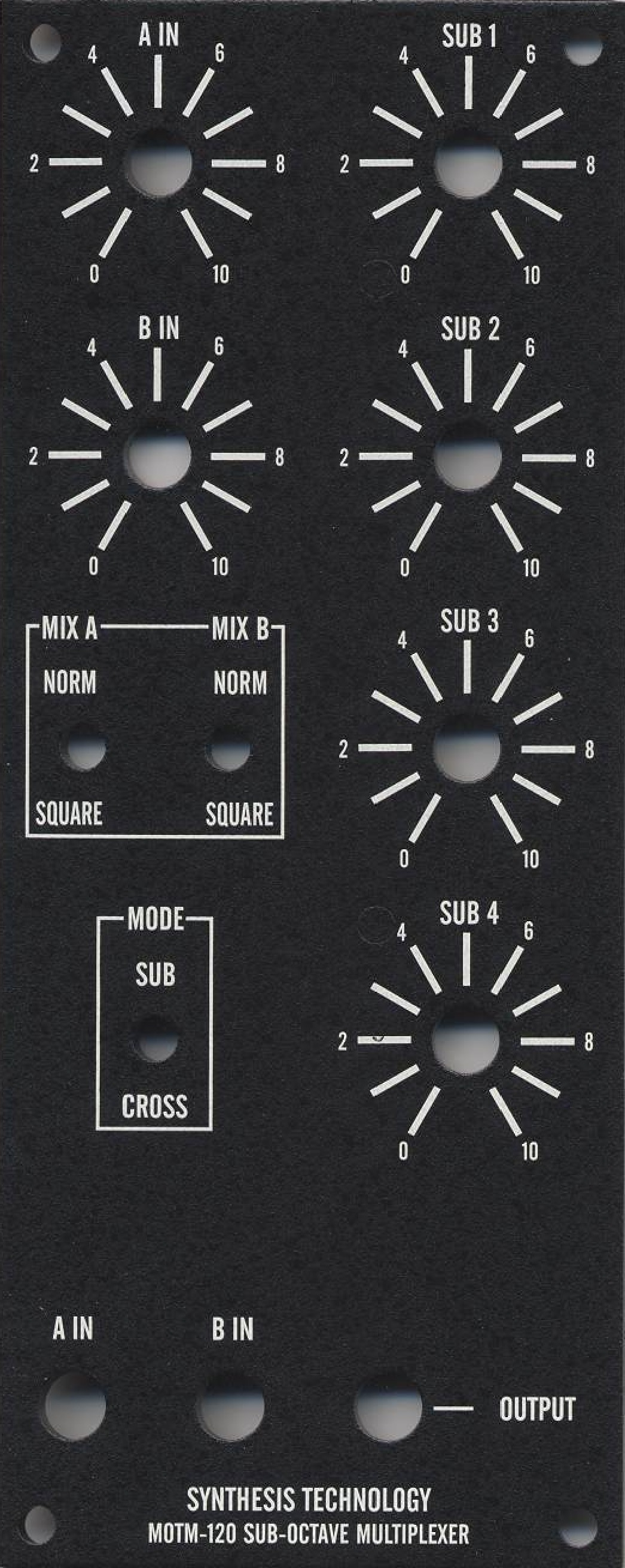
Paul Writes: "The MOTM-120 is a Synthesis Technology exclusive design. Based on an article in Electronotes, we have updated, improved, and added features to create a truly unique module. "The MOTM-120 contains 2 4-stage sub-octave dividers, a digital mux, and 4 digital ring modulators. It operates in one of two modes, selected by the cleverly named MODE switch. "In the simplest operation (MODE is set to SUB), a single input is fed into the A IN jack. The signal passes through a level comparator, whose lower threshold is 80mv pk-pk. When the input exceeds this, a 4-bit binary counter is clocked with the input signal. This generates the lower 4 sub-octaves. These are then mixed by 4 individual pots along with the input signal. A switch selects either the original source mixed in, OR the "squared" version of the input. "The additional 4 sub-octaves (similar to pulling out lower octave drawbars on a Hammond) greatly fatten up the bottom end of any signal. Even a simple sine or triangle will punch through in the mix. "Lots of synths have a single sub-octave, but we give you FOUR! "But the real fun starts when you flip the MODE switch to CROSS. In this mode, 2 input signals are required. Each is divided into their respective 4 sub-octaves, then each sub-octave is ring modulated with each other! Since we are in the digital domain, it's easy to ring modulate (you'll have to buy one to see how we did it!). This results are simply awesome and bizarre. If A IN is audio, but B IN is from a LFO, what you hear is a 16-cycle patteren of the sub-octaves getting multiplexed in. As the B IN signal is raised into audio frequencies, the results are HUGE chordal timbres with lively beat frequencies. Electronotes used to describe this as Waveform Animation, and that's a pretty accurate description. "The MOTM-120 is a powerful addition to your studio. The wimpiest digital synth can be turned into a growling monster!"
|
||||||
Modifications |
||||||
|
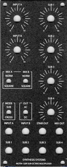
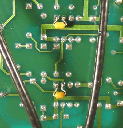
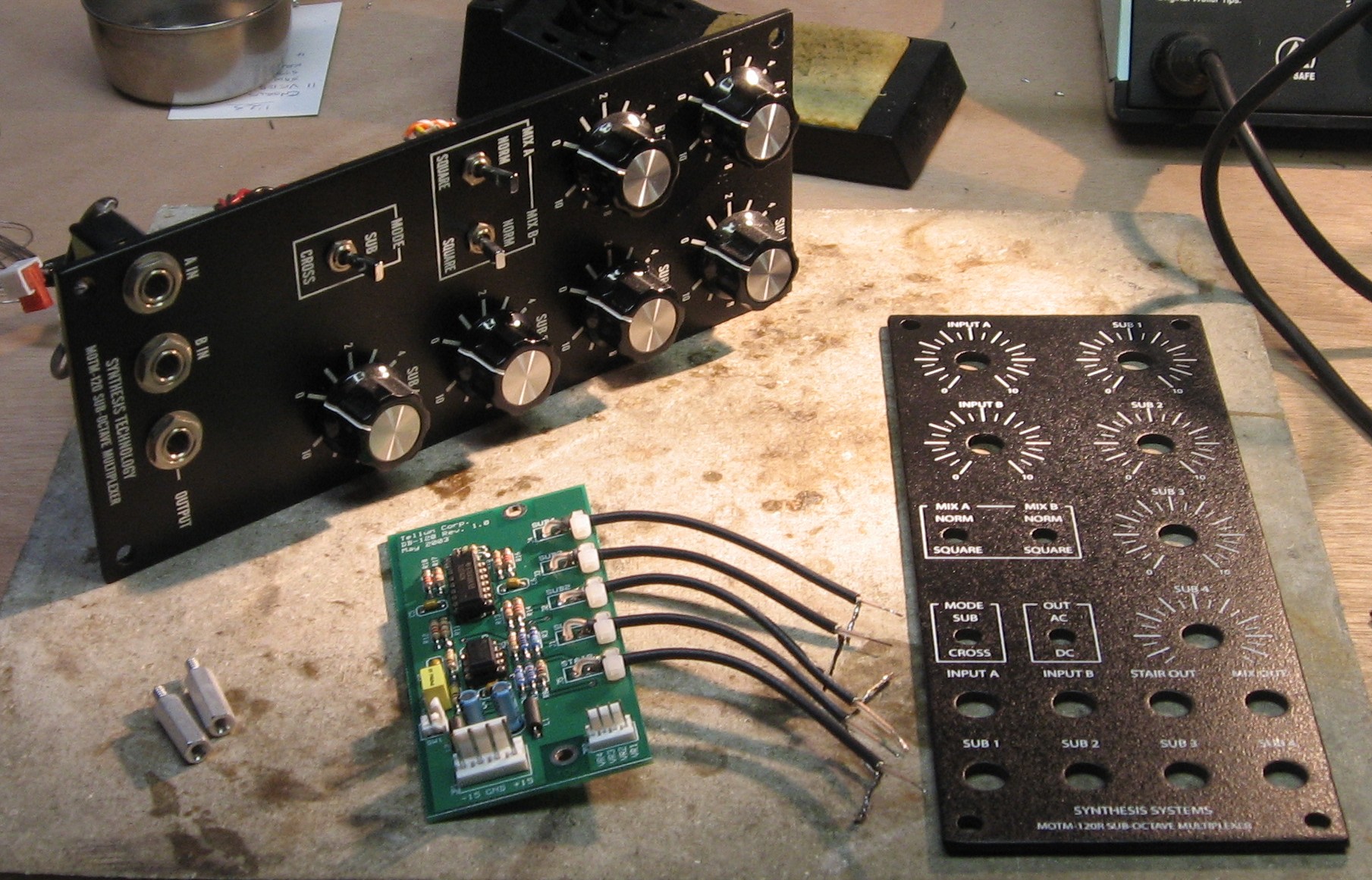
Richard Brewster sent us this bit of 120DB history and commentary (thanks, Richard): "I modified the MOTM-120 module because I saw potential CV (Control Voltage) applications. It was conceived by Bernie Hutchins (Electronotes) and by Paul Schreiber as an audio sub-octave generator. That's why it has an AC-coupling cap in the signal path. My first mod was to remove that cap. (It's optional now with the external switch added for the 120R). Then I could get a low frequency stepping pattern out and use it to modulate a VCO. I noticed that the 4 suboctaves would be handy to have separately. (My buffer circuit was made into the CGS56 pulse buffer by Ken Stone - at my request, because I wanted a lot of these.) I also thought a staircase wave would be fun and I wanted to use 8 jacks on the panel. "You can find a lot of interesting posts the MOTM list by logging into Yahoo Groups and searching the archives. My first post about the 120 mod was in January 2003. http://launch.groups.yahoo.com/group/motm/message/18091 "The original was done on a prototype board. I drilled the MOTM-120 panel to add the 4 SUB outputs. Later I rebuilt with a Stooge panel and Scott's DB-120 board. The DB-120 manual lists me as the circuit designer. But this circuit is so simple, it hardly bears credit; many of Scott's are much more inventive. I also contributed some ideas to the DB-800 board, the most interesting of which is the clipper. I took that clipper circuit straight out of Electronotes. I think it's good to spread information like this for people like yourself who are discovering synth DIY. ..." For those who are constructing a 120, Larry Hendry's site doesn't include MOTM-120 construction photos, so we're going to be extra careful about being complete in ours. Richard Brewster has photos on his site—they show the 120DB and will be helpful: 120 side, 120 back. Richard has also made some comments on construction which we included lower on this page. It should probably be noted that, as you can see from Richard and Scott's photos, when we convert to the 120R face plate, we'll also need to re-mount the Motherboard using a "Stooge 4 POT Mounting Bracket." Also, we've decided to illustrate some of the special techniques we used in constructing and hooking up the 120DB—so there are a lot of pictures here, OK? Many more than are probably necessary. But we're going for the "How to Keep Your Volkswagen Alive" approach (the John Muir book—I'm dating myself)... see—we're really just idiots ourselves—well—not Will—he's 15—but I certainly am—and we figure these photos might help other ambitious idiots someday... ya never know. We moved a few to a separate page—the link's below. March, 2010 Scott Juskiw posted a mod on his site describing the addition of two "Deglitching Capacitors" to the comparitors. "...I can confirm that this simple addition of two capacitors cures all kinds of ills with the MOTM-120 (and the modified MOTM-120R). The exact value of the capacitor isn't all that important, anything from 15 pF to 33 pF should work. The best place to add these two capacitors is on the underside of the PCB, directly between pins 2 and 1 of both comparators. Yes, it's a bit of work to remove the mounting bracket to reach the underside, but there isn't really any good place to add these capacitors on the topside. See the picture below for an example."
|
||||||
Parts |
||||||
|
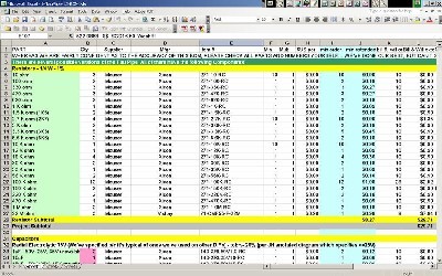
In 2008 (or thereabouts), Synthesis Technology stopped producing full-blown kits, and moved toward what Paul calls "2.0" (two-dot-oh) DIY. This assumes the builder will buy certain parts from Synthesis Technology - PCB, Panel, and in some cases a Special Parts Kit of the particularly hard to find parts - and will get the rest of the parts from Mouser or Digikey or - well - wherever. For those who are building this as a "two-dot-oh" project, Will and I, with feedback and review from others, have developed a parts-list / bill-of-materials in the form of an XL spreadsheet (as usual). Please don't take it as gospel. We've been over and over it and are relatively confident in our specifications - and we hear that several people have used it successfully so you should be good. The BOM assumes that you get the "extra parts kit" from Synthesis Tech. Synthesis Technology offers some parts like pots and knobs at particularly good prices... these options are offered in the BOM. Please note that this BOM does not include the parts for the Tellun Daughter-board addition. Those parts are detailed in Scott Juskiw's "User Manual" on his site.
Click here to download our XL spreadsheet Parts List |
||||||
Panel |
||||||
|
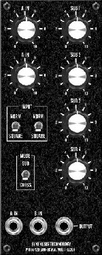
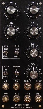
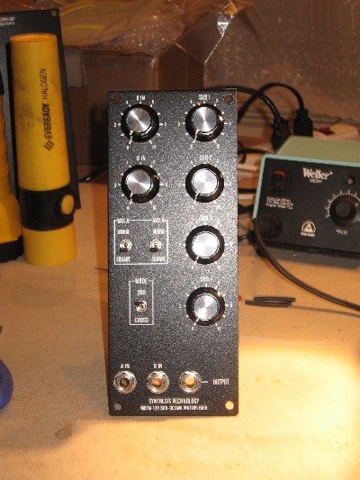
If you're building this as a "two-dot-oh" project, we also assume you get the panel from Synthesis Technology (the one on the left) unless you happen to have an old 120 Daughter board - in which case, the Bridechamber panel is what you'll want (the one on the right):
|
||||||
Preparation |
||||||
|
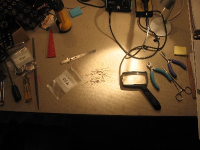
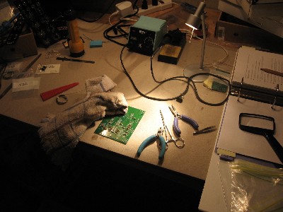
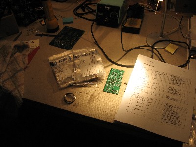
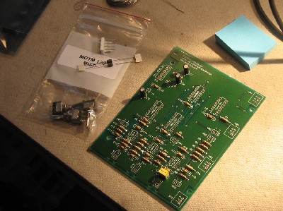
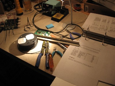
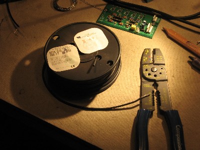
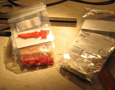
Back in march, our parts came from Mouser. We ordered per Scott's parts list—we ordered with several mods in mind—the 120DB, and other little tweaks that are listed on sites we found. Because some things have a minimum order quantity (and even when they don't we always order more) we've ended up with plenty of spares. I think the single most expensive thing in this order was the spool of coax wire of which there's far more than we need—but my experience has been that I never regret having extra supplies. Over the next years, I have no doubt that I'll use the stuff—I always seem to. Richard Brewster: "I balked at the Mouser price for 100 feet of RG-174/U coax, when my supply ran out. I found some military grade RG-174/U on Ebay that was selling in 25 foot lots for $2.00. ($5.37 total with shipping.) Remember to check Ebay for odd parts." |
||||||
|
|
||||||
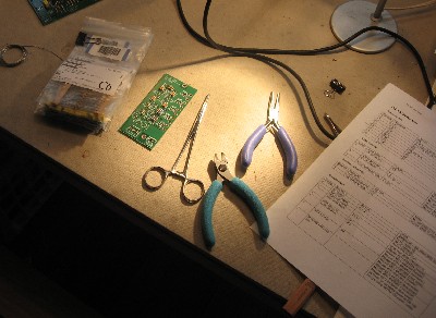
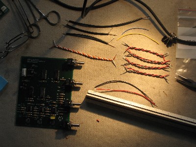
Construction Phase 1
All the stuff in Phase 1 gets soldered using "Organic" Solder. At every break in the action, we wash the board off to get rid of the flux. |
||||||
|
A preliminary note—Scott Juskiw mentions a modification to the 120 involving replacing R10 with a 200K resistor. Because, as he later notes, the addition of the DB120 makes this modification unnecessary, we're leaving this modification off. But you might want to consider it if you're not doing the 120DB modification. |
||||||
|
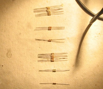
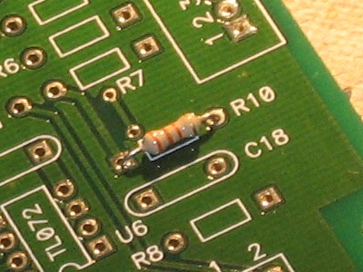
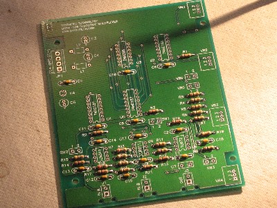
This is also the resistor that Scott Juskiw suggests modifying if you're not going to do the 120DB modification. We're skipping this modification and this shows the 100K resistor stuffed into R10. What this photo also illustrates is how we orient all the resistors so the the colors read from left to right according to the name of the resistor on the PCB. So—it reads Orange, Orange, Orange (the value) then the gold (5%) and it's in the same orientation of the "R10" text.
As usual with us, whereas we are vigilant about orienting all the resistors, caps, etc. consistently so their values can be read easily (in case we need to trouble-shoot them later), we oriented the resistors with the "Tolerance" stripe on the left (relative to the text on the pcb). Why did we do it this way? 'Cause the gold stripe is so pretty and easy to see (of course)... and so we put it on the left - well - just because. You might want to do it the opposite way. (For the table of resistor value markings click here.) |
||||||
|
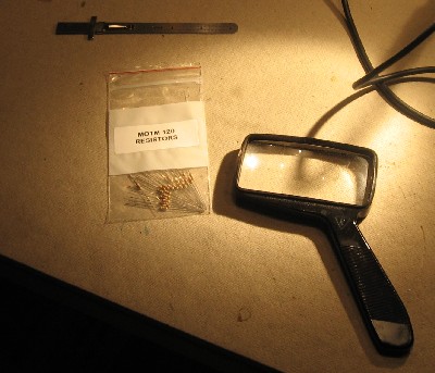
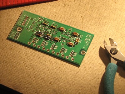
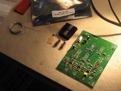
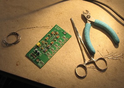
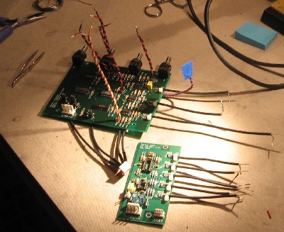
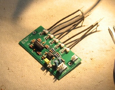
120DB Resistors
While the Motherboard is drying, we decided to solder the resistors in the Daughter Board. So we got out our collection of resistors we bought from Mouser for this purpose, got out Scott's 120DB User's Guide and began.
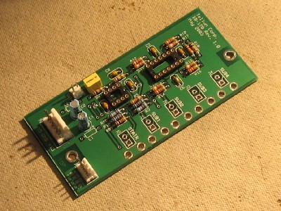
120 Motherboard Capacitors, plugs, Semiconductors
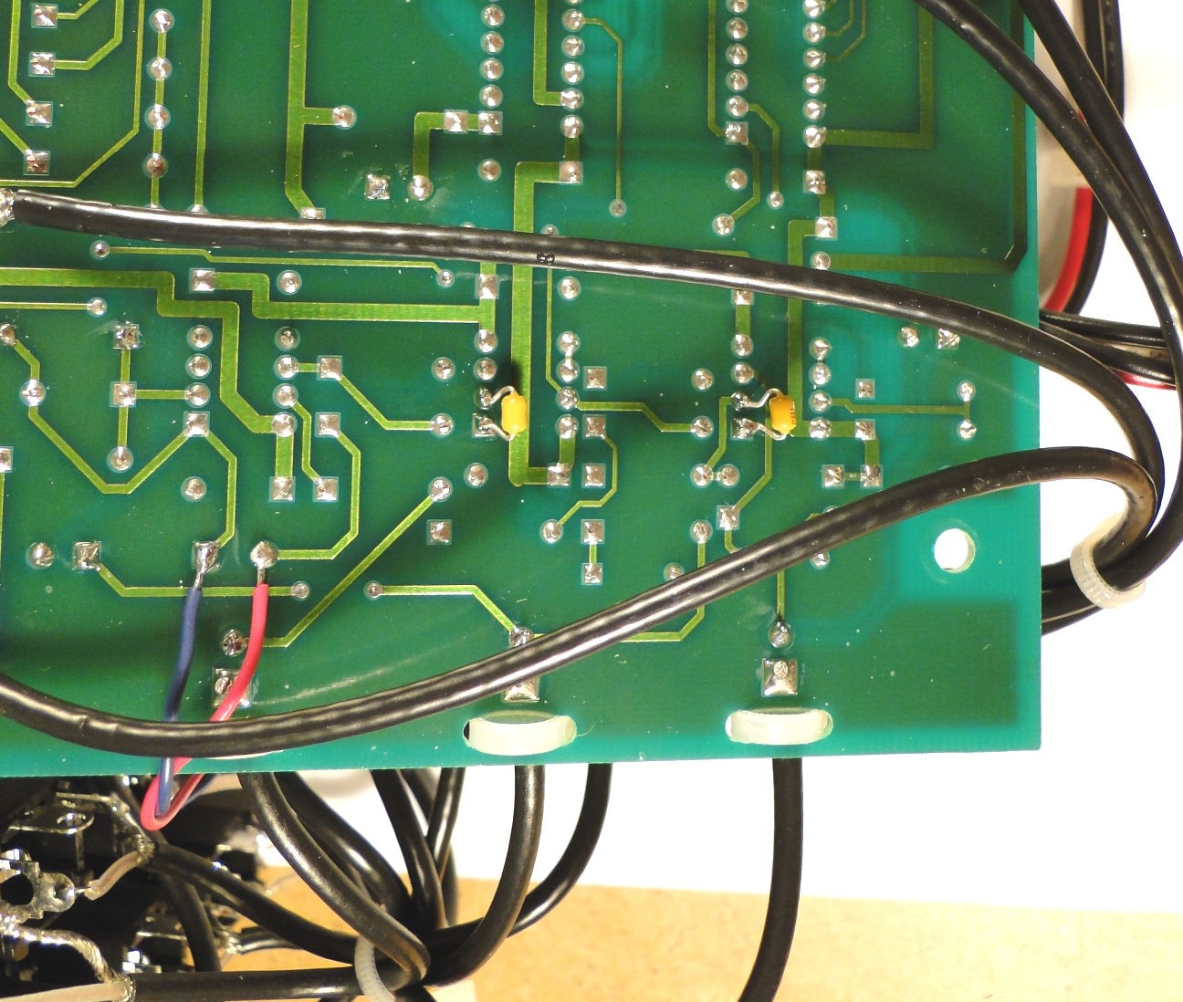
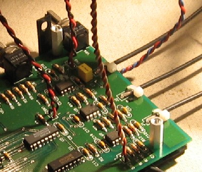
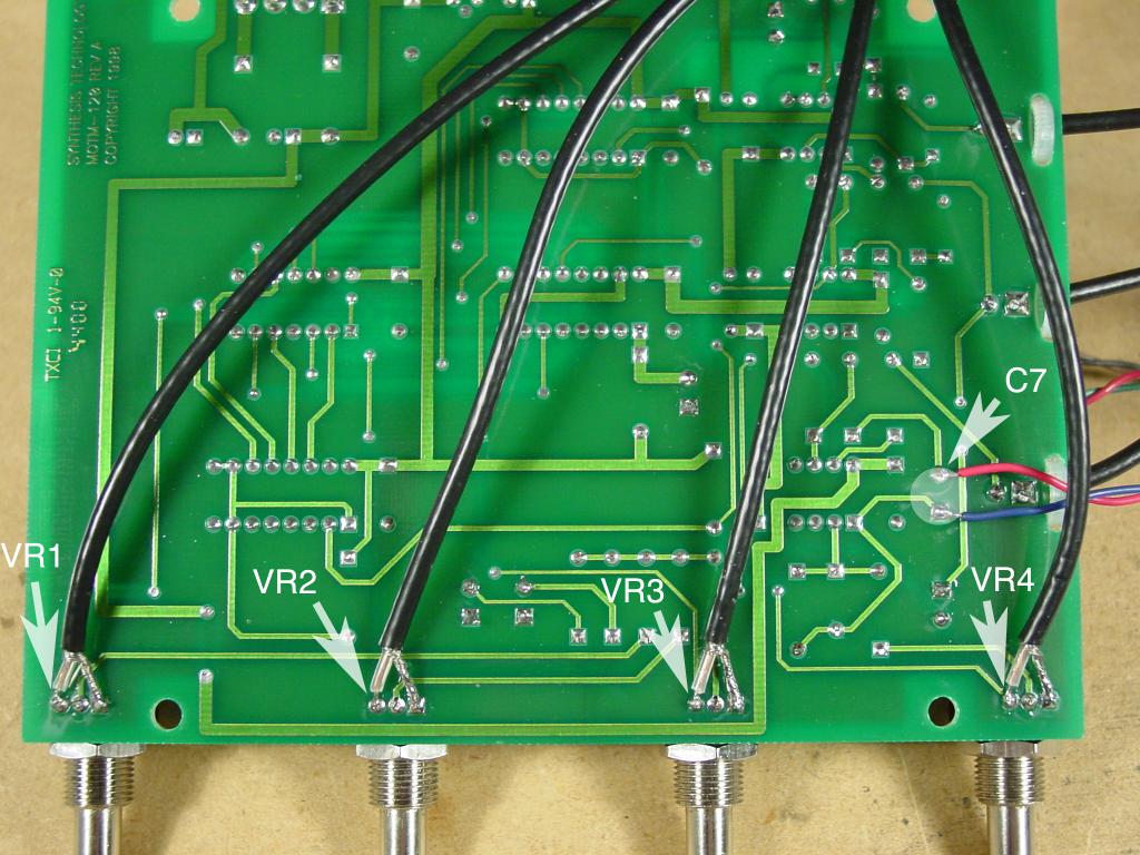
The Comparator Caps Modification Although we did this mod after the fact, this would be the best time to do it during construction. Just turn the PCB over and solder a 22p cap (mouser #147-75-220-RC) between pins 1 & 2 of each comparator.
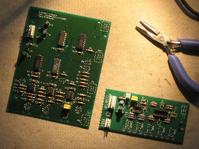
120DB Capacitors, plugs, ICs
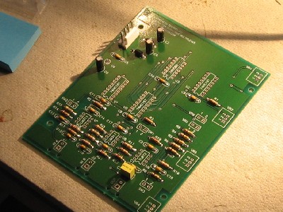
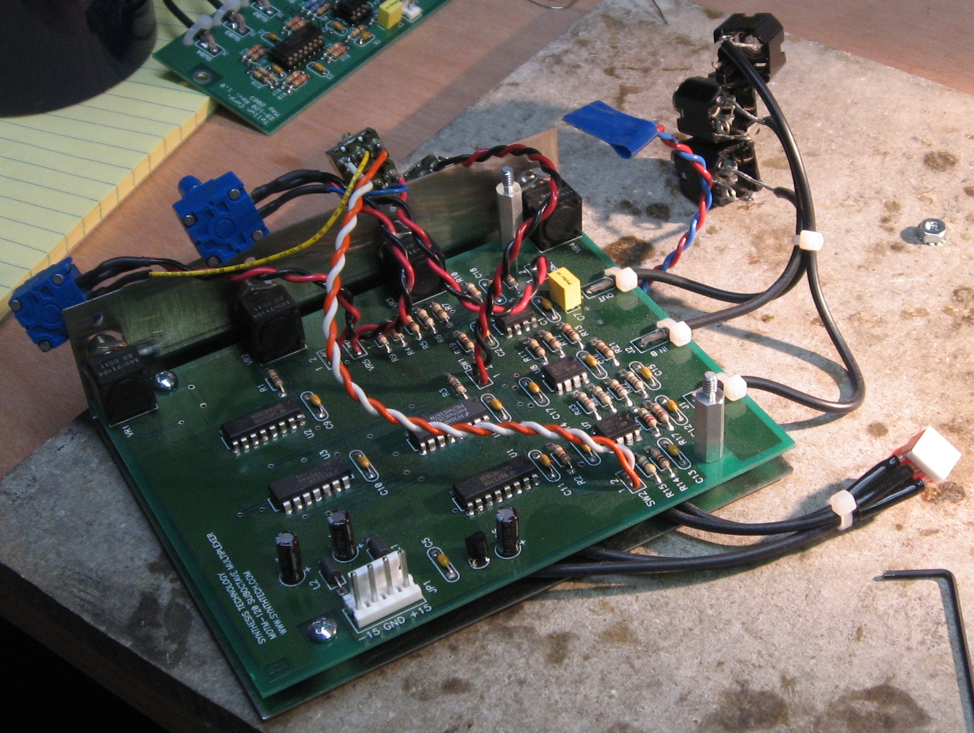
this shows the 2 PCBs—on the 120DB, the ferrite beads and the plugs for the ICs are in, but we're going to delay actually plugging in the ICs until the last thing. |
||||||
|
|
||||||
Construction Phase 2 |
||||||
|
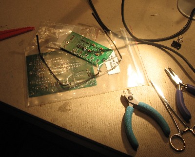
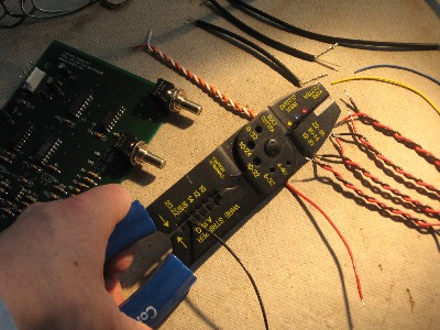
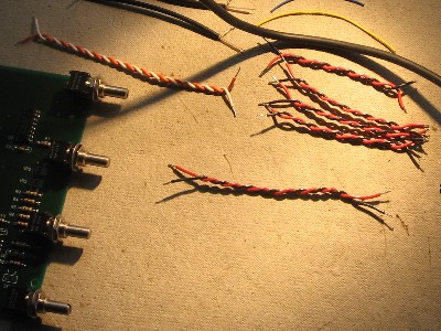
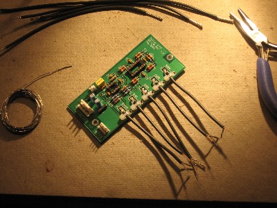
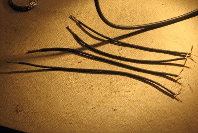
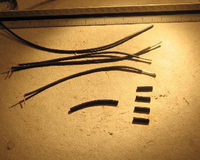
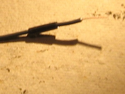
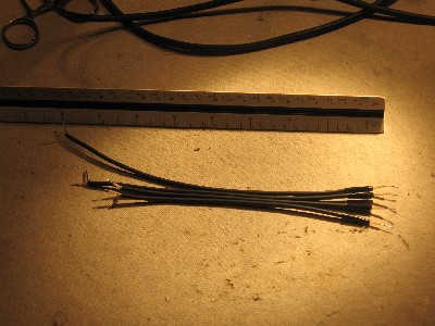
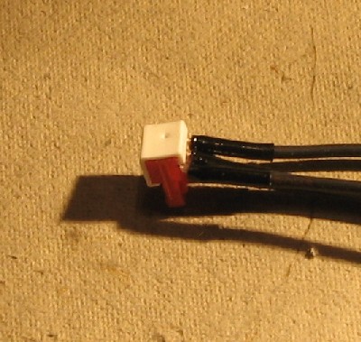
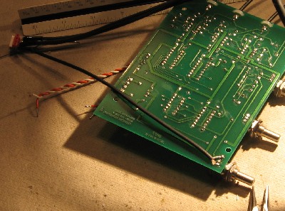
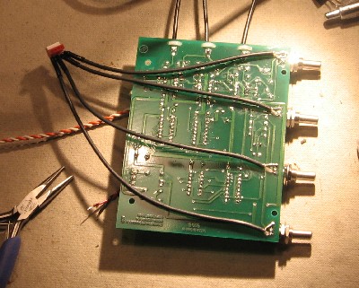
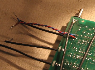
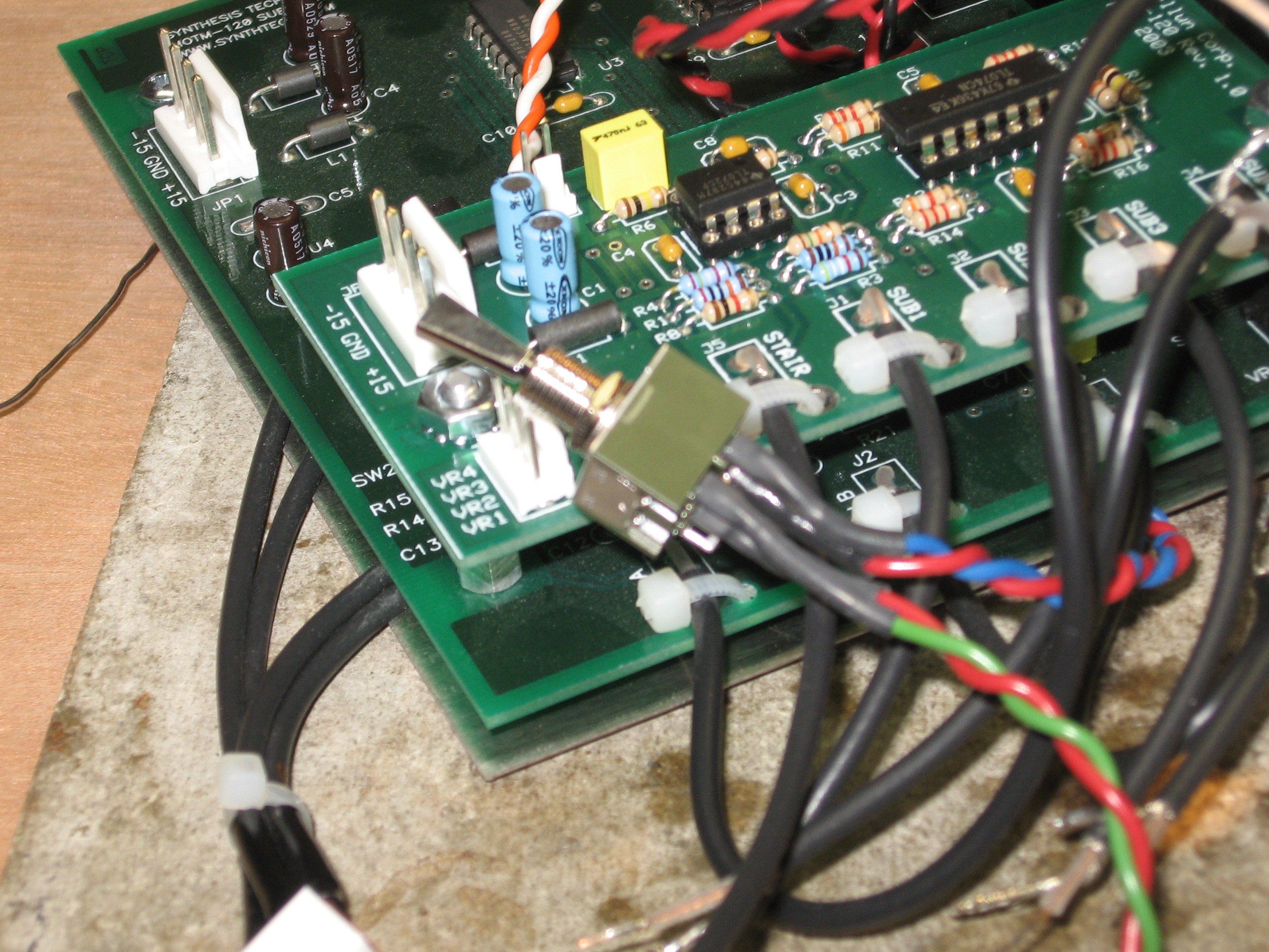
120DB Wires
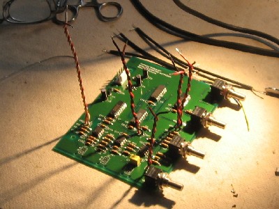
120 Motherboard modification
|
||||||
|
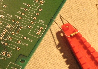
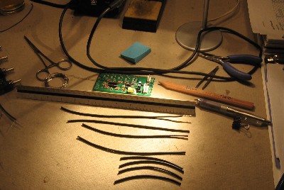
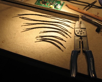
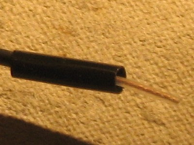
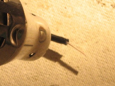
we decided to put the plug on the coax first, then solder them onto the motherboard. Perhaps we're being overly cautious—but we figured that any strain we put on the wires while we put the plug on them could hurt the solder joints if we did the soldering first. <shrug>
|
||||||
|
|
||||||
|
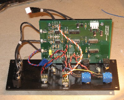
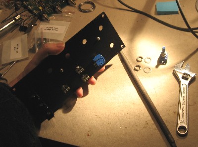
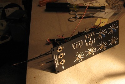
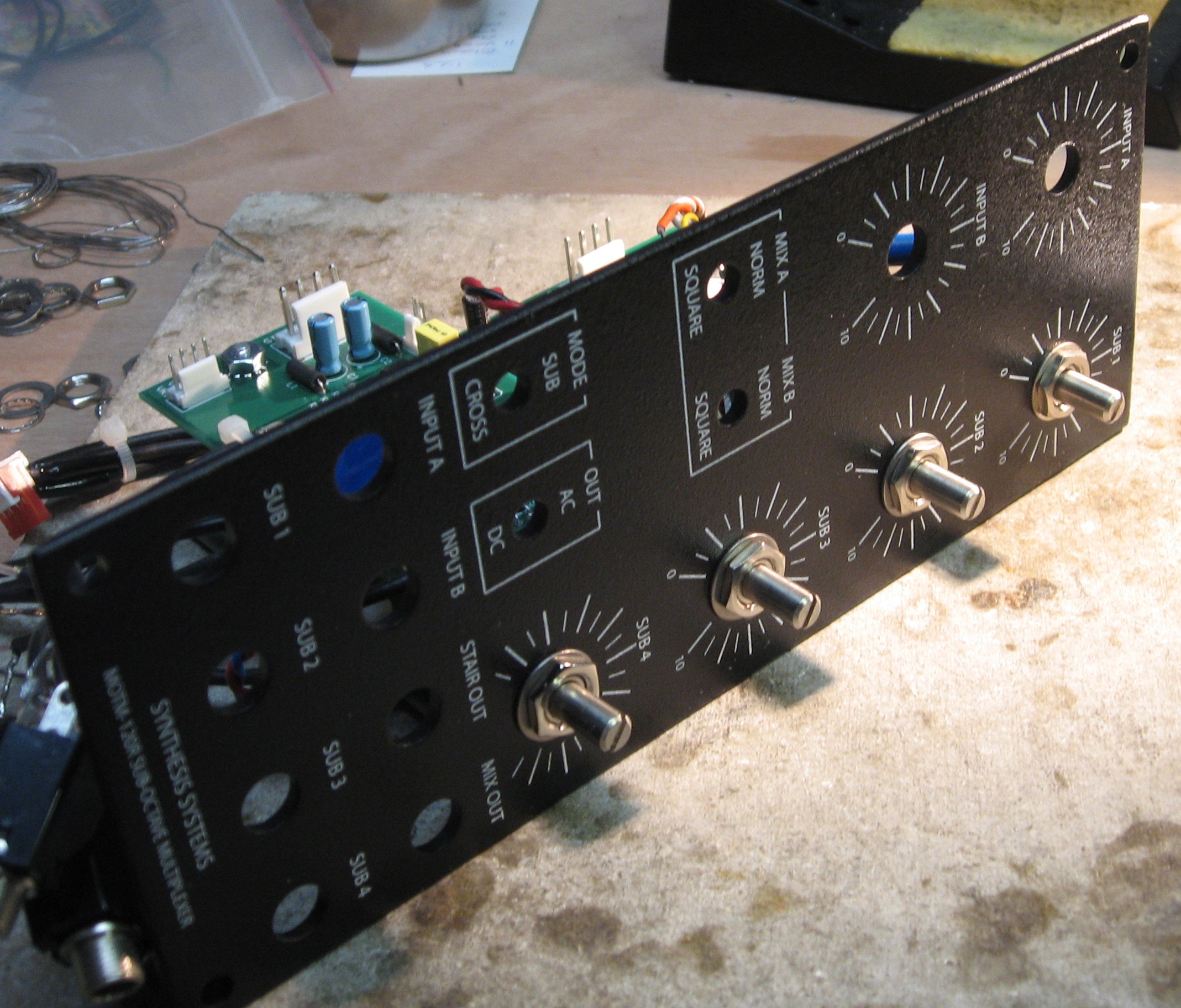
Panel mounted components |
||||||
|
Someday, we'll get hold of a "120R" panel and we'll get the 120DB back out and hook everything up right as rain. But until we do, we're going to continue our construction using the standard panel.
|
||||||
|
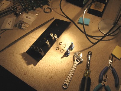
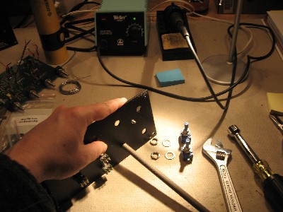
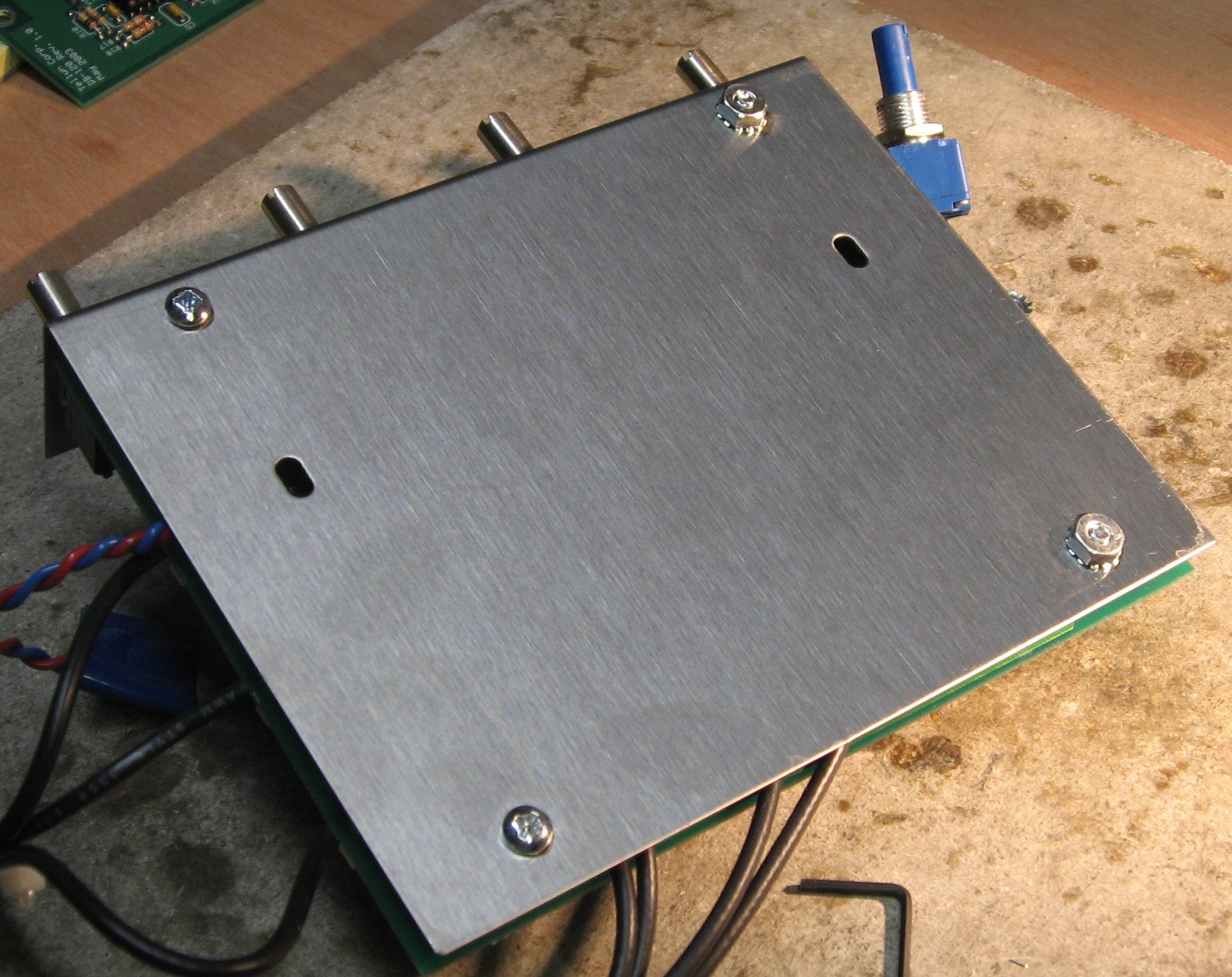
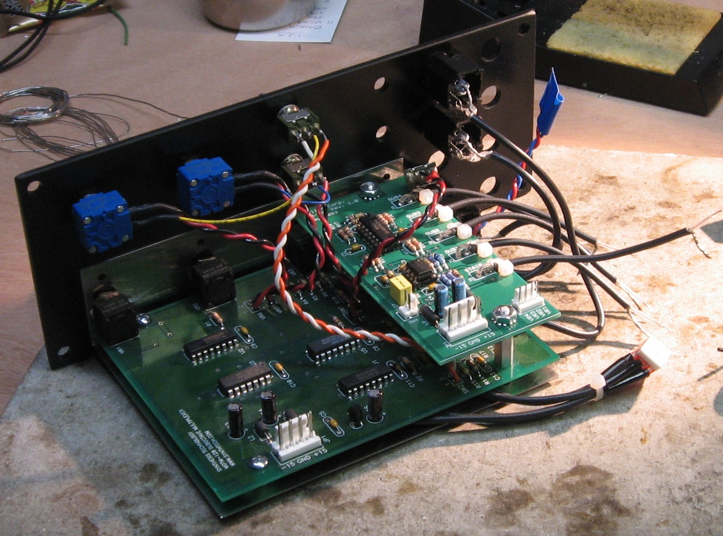
Mounting Bracket |
||||||
|
|
||||||
|
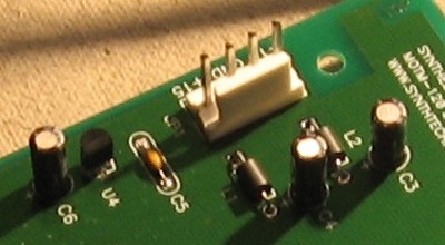
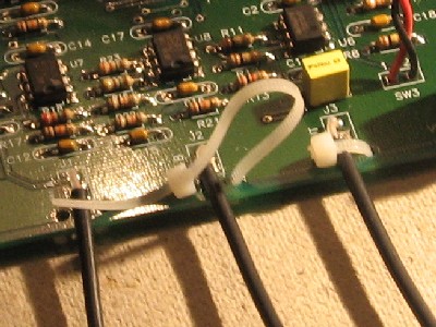
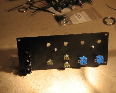
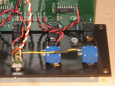
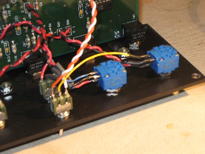
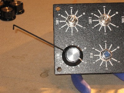
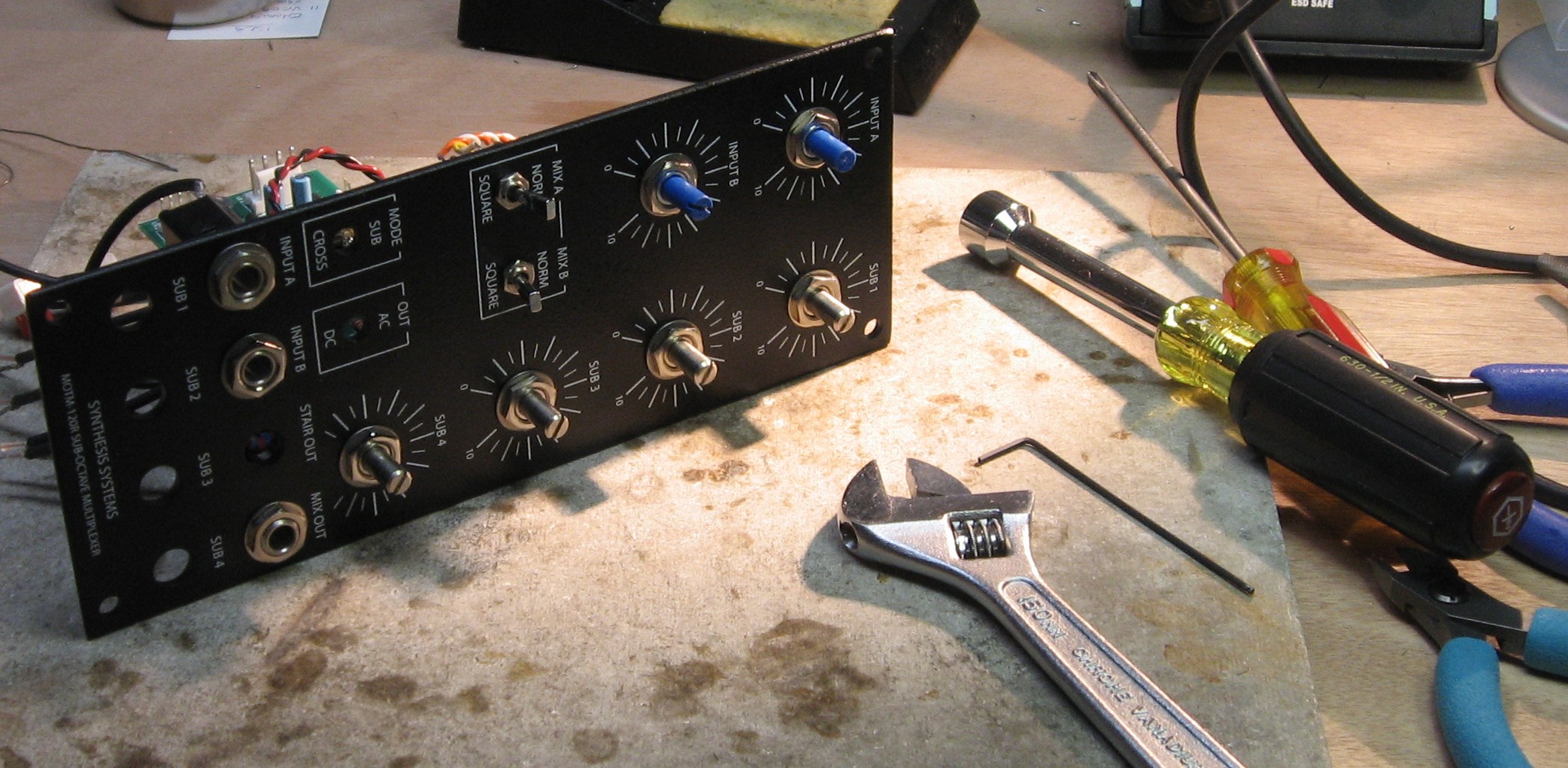
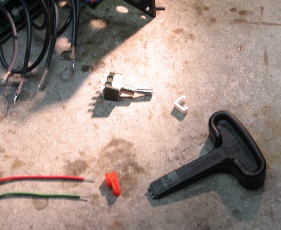
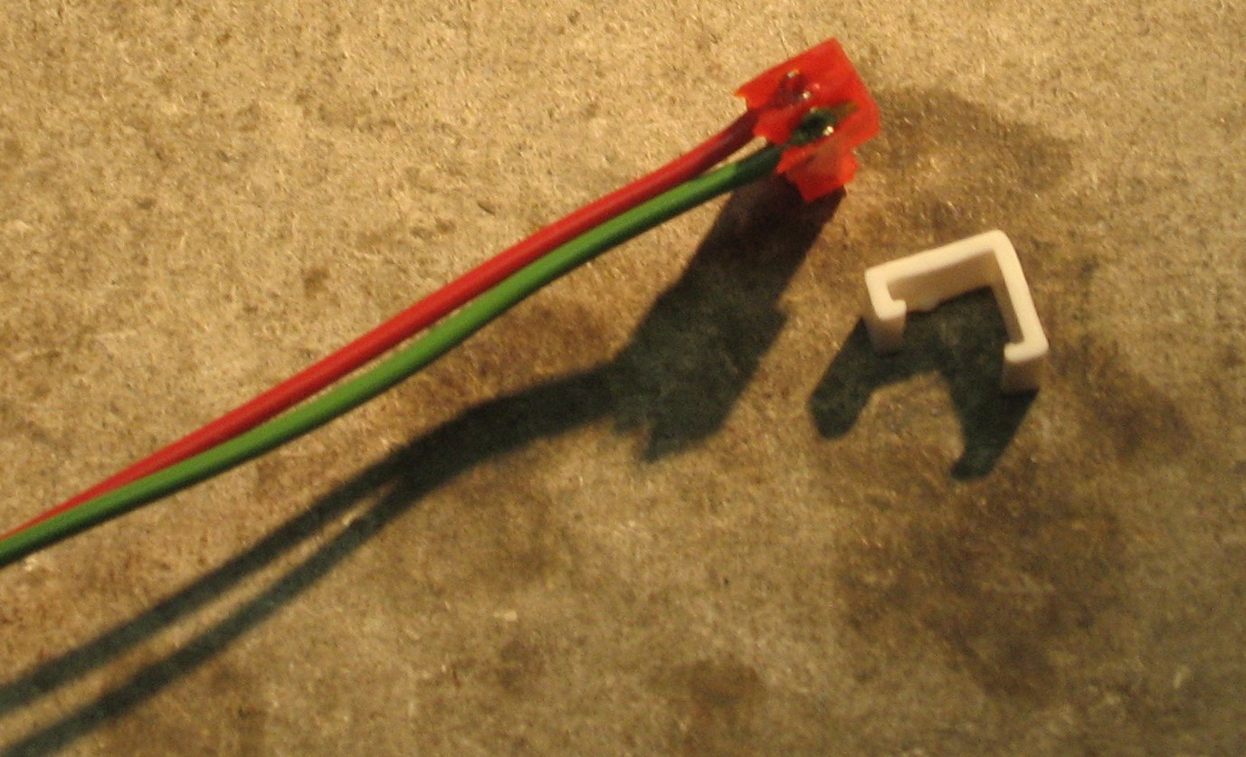
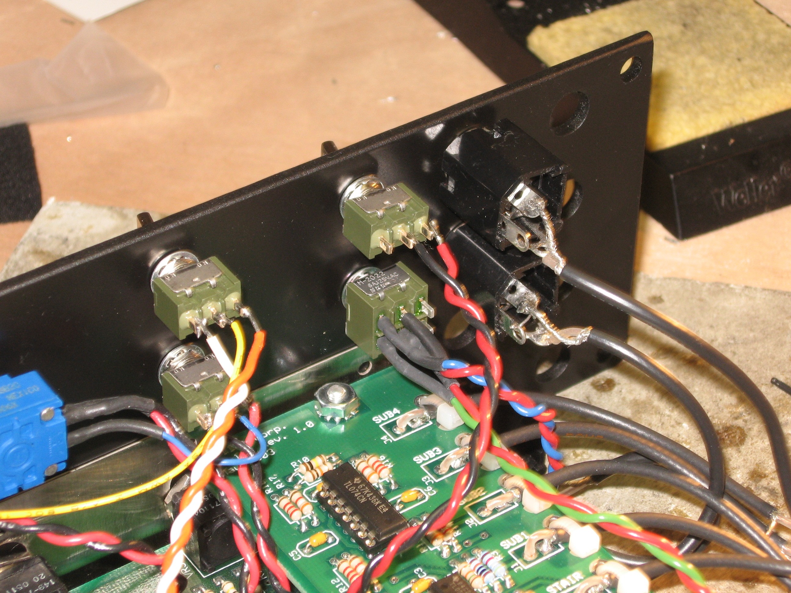
Panel Connections |
||||||
|
|
||||||
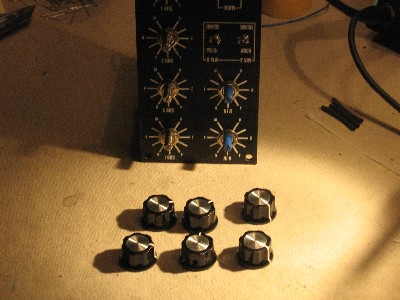
|
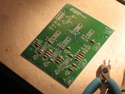
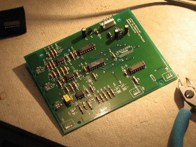
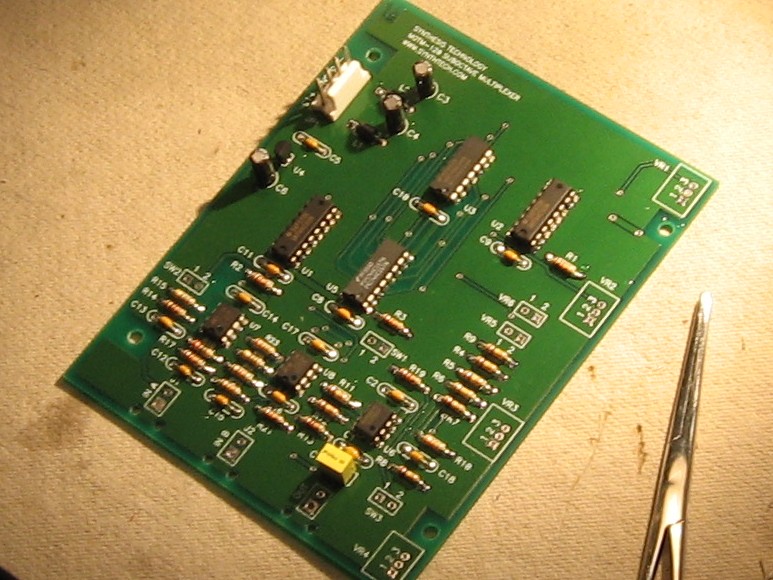
Construction done! |
||||||
|
|
||||||
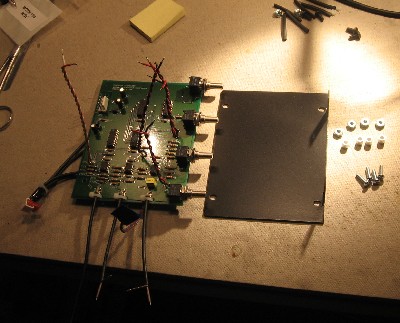
Construction Phase 3 - DB installation |
||||||
|
... which we got from Bridechamber in late 2008 and installed in Jan 2009 like this:
|
||||||
|
Panel Connections |
||||||
|
The OUT AC/DC switch
The MODE switch
Jacks - construction done!
|
||||||
Set up / Testing |
||||||
Use Notes |
||||||
|
|
||||||


|
The fine Print: Use this site at your own risk. We are self-proclaimed idiots and any use of this site and any materials presented herein should be taken with a grain of Kosher salt. If the info is useful - more's the better. Bill and Will © 2005-2011 all frilling rights reserved
|