Bill and Will's Synth Construction
|
|
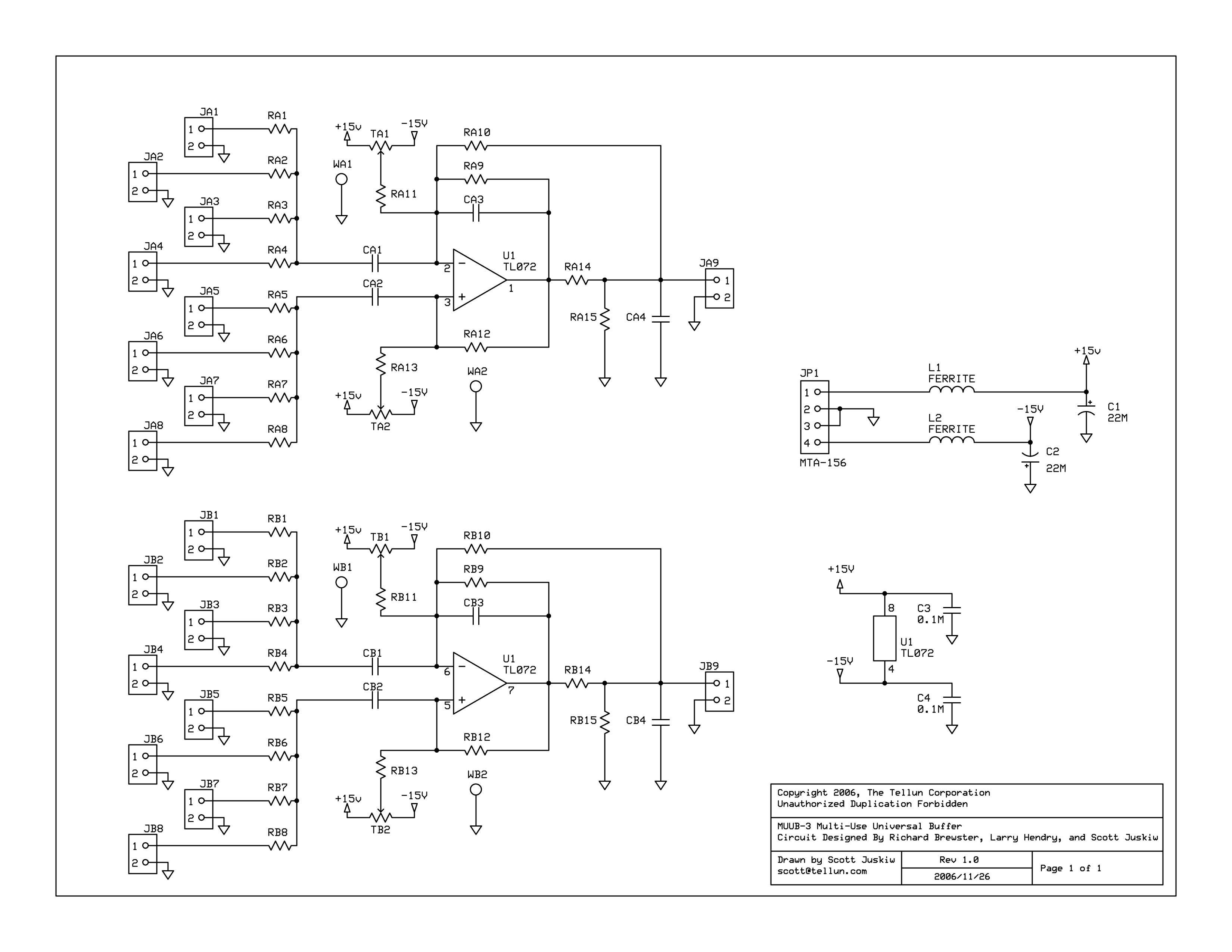
Click here to download a powerpoint file with our charts of this pcb. All the images below are hyperlinked to larger, higher-resolution images so if you click on them, the bigger image should load into your browser. Here is Scott's drawing of the MUUB3 schematics (click on the image for a larger, higher resolution one):
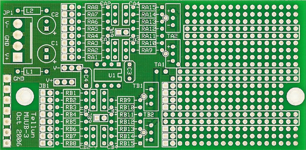
Click here to download the .pdf version. Here is Scott's drawing of the MUUB3 overlay:
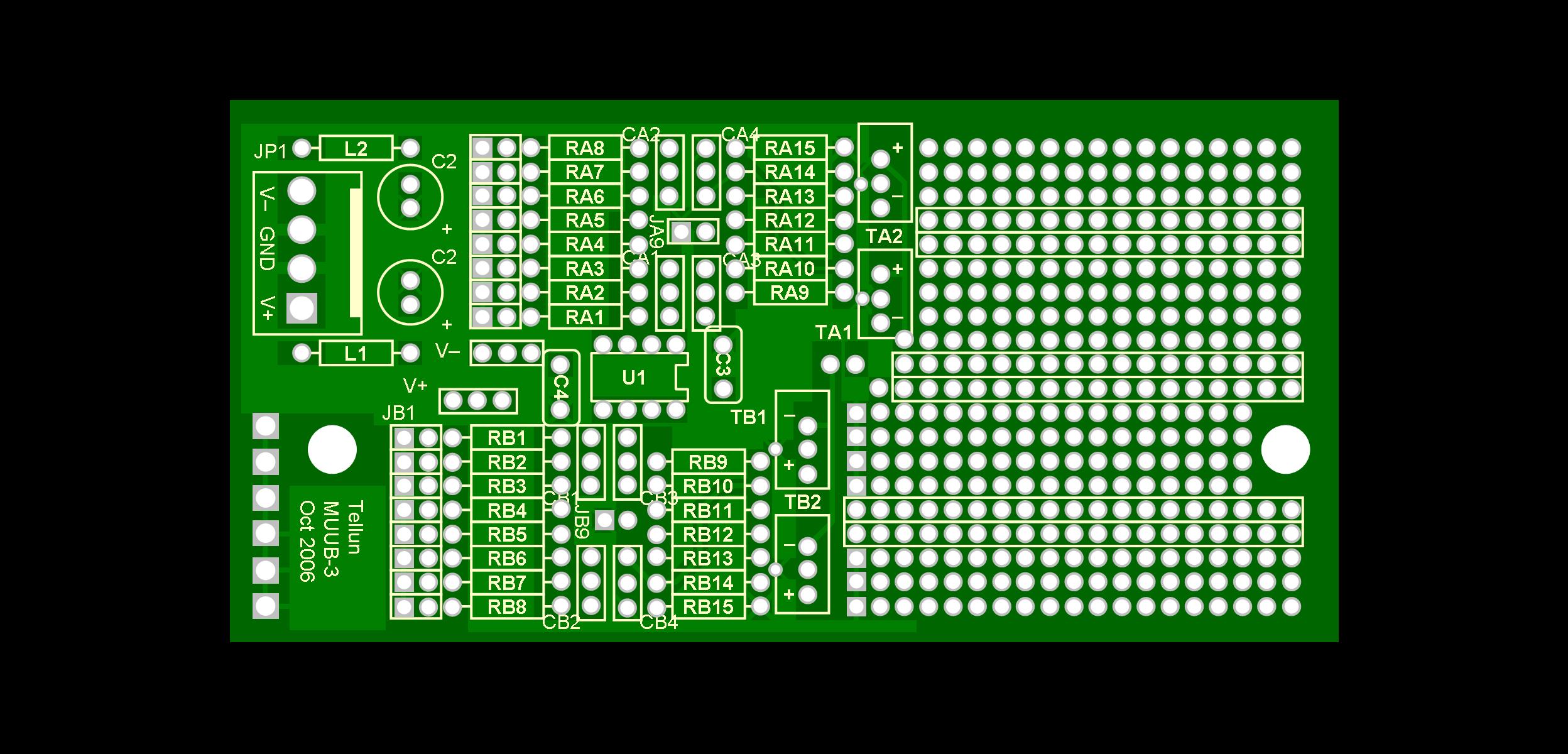
Here's a drawing of the MUUB3 as seen from the top. The exact location of the pads is a little off in a couple places, but you can accurately see where a 1/10 in spacing vs a 2/10 in spacing is, for instance... anywhere it really counts, anyway:
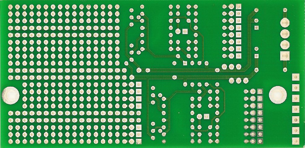
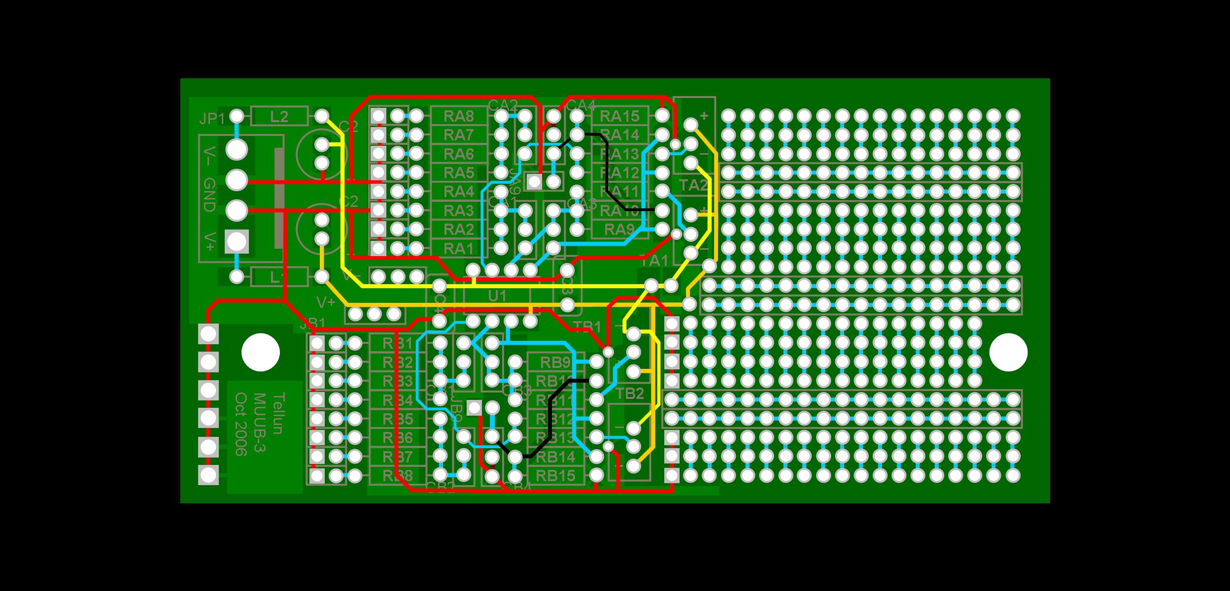
The following drawing illustrates how the traces hook things up. Ground - Red. The red lines show the pads that hook up to Ground by way of the top traces. The dark red lines (there are only a couple dinky ones) show a couple pads connected to ground by way of a trace on the back. -15V - Yellow (some traces are on front, some on back) +15V - Orange (some traces are on front, some on back) Other traces on front - Black Other traces on back - Blue
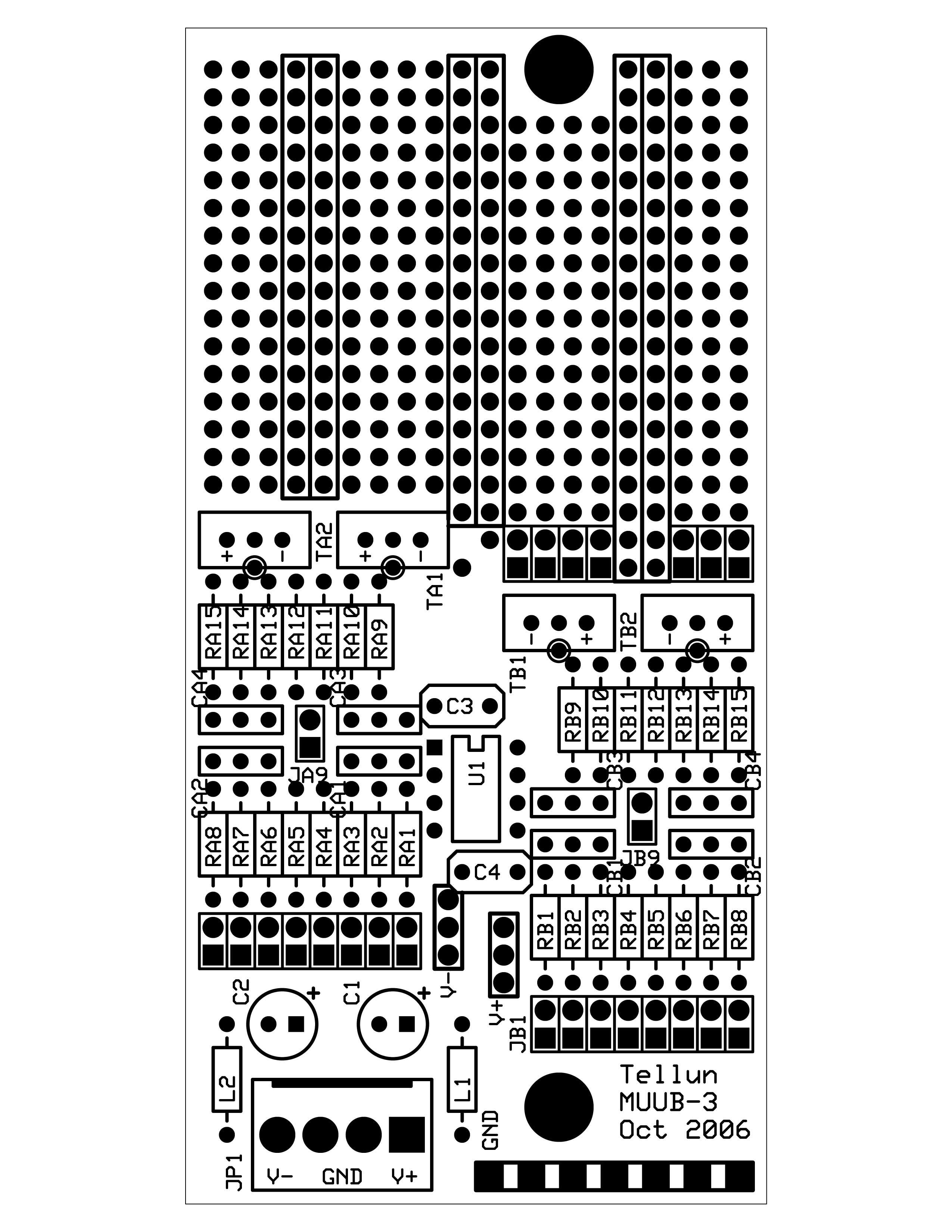
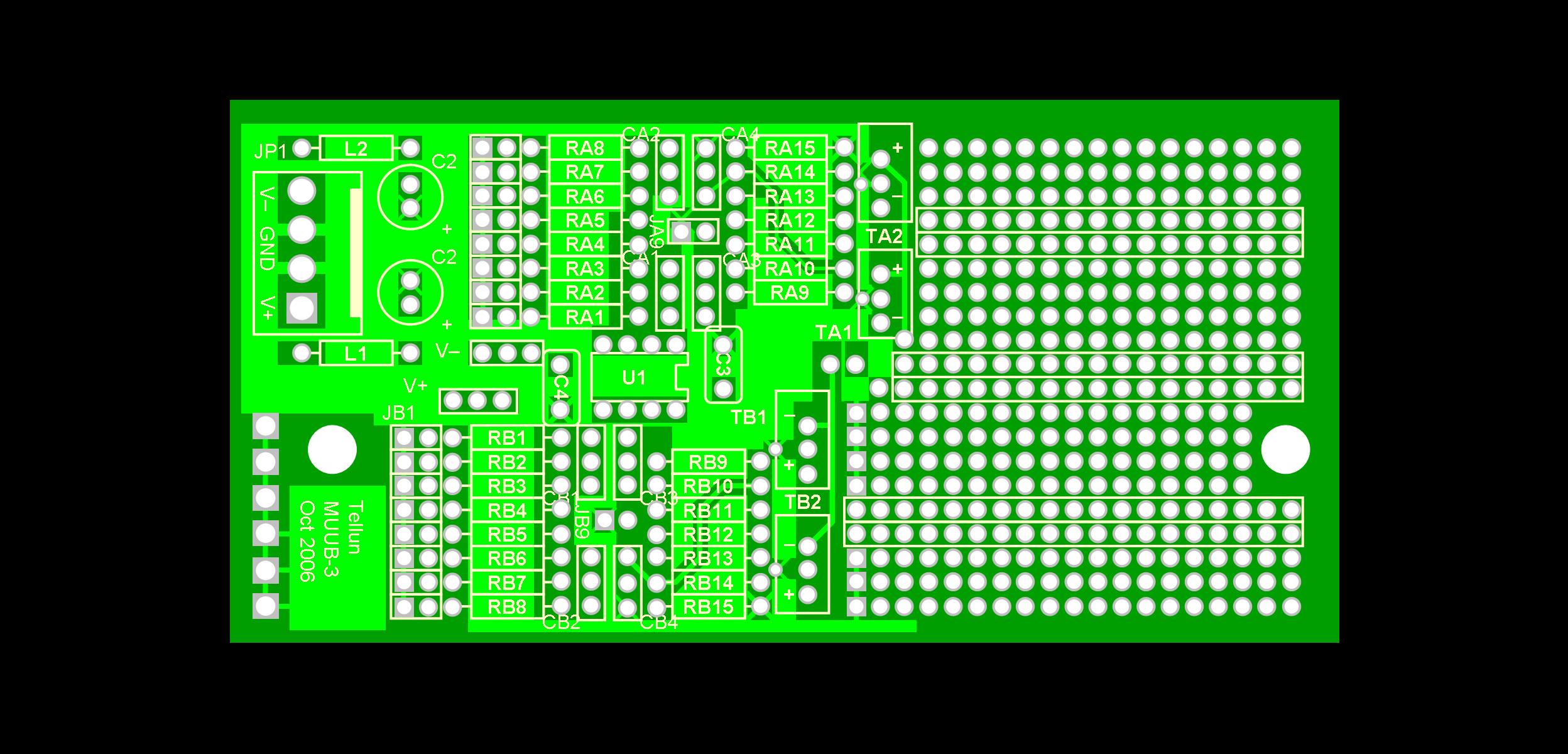
Actual top traces:
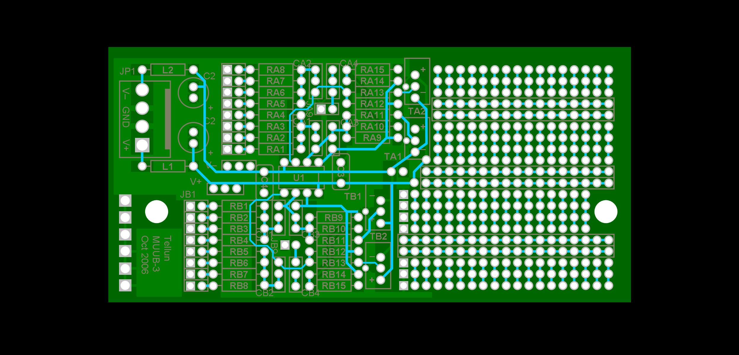
Bottom traces viewed as if the pcb is transparet:
|