Bill and Will's Synth
|
1. Units of measure |
|
English vs Metric: When we actually measured some of the Synthesis Technology panels, they seem to measure more perfectly in metric units but Paul' specs are clearly in English units. |
2. The MOTM "Grid" |
|
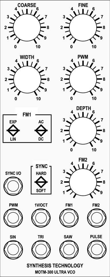
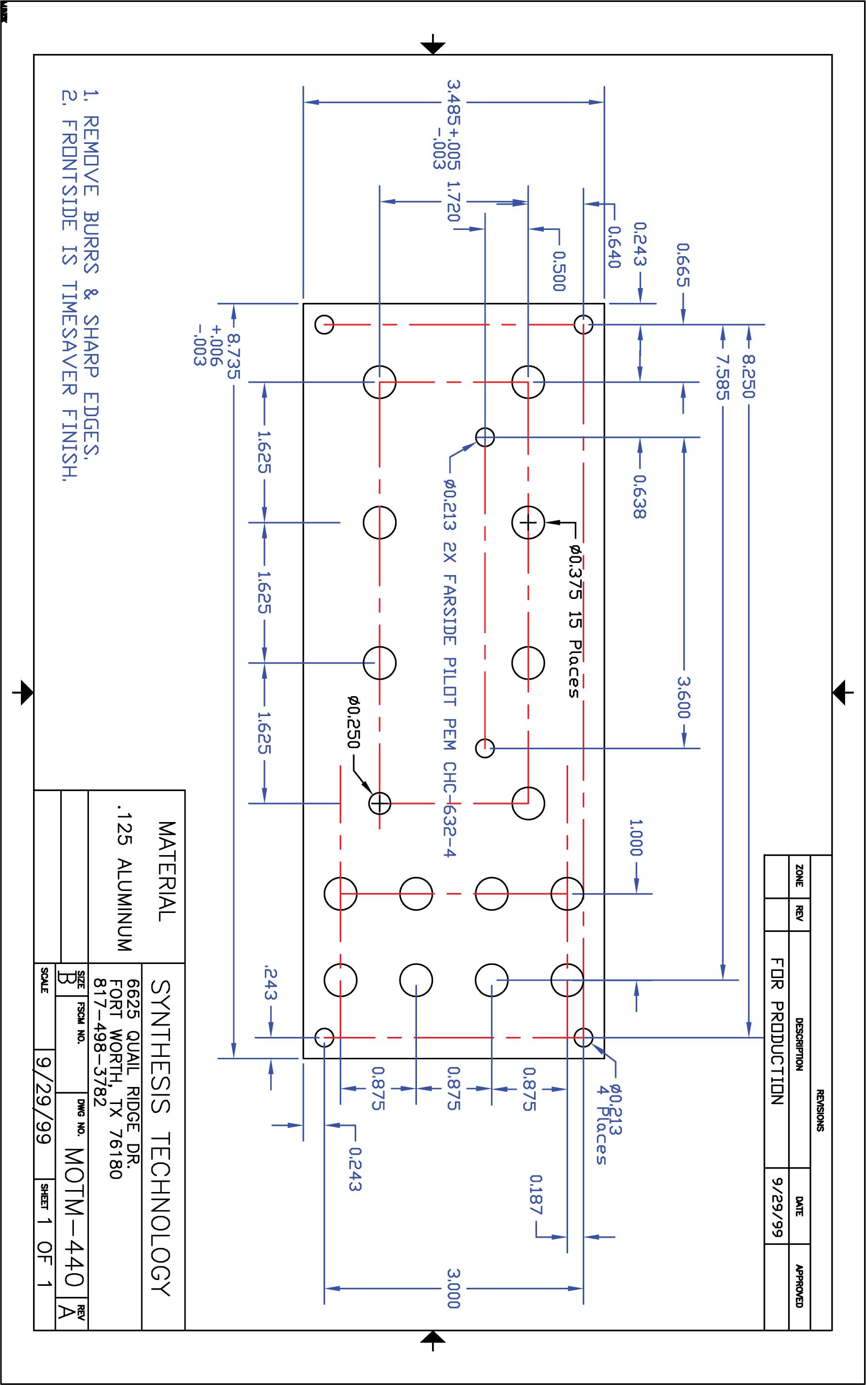
POTs vs Jacks No matter what the units of measure, there are two standard vertical distances used on MOTM panels; one for POTs at the top of panels and one for Jacks at the bottom. Where rows of these elements overlap, they generally stick to their own vertical grids. Horizontally, the POTs are centered in 1U panel space whereas the jacks are centered in half a panel space. Other elements fit into these grids as seems appropriate and, occasionally, a switch or LED will appear off the grid to save space. Paul has this example of his specifications for the MOTM440 panel on his site, clearly using English measure - click here to download Paul's pdf file, click on the image to download a large .jpg:
Oh - also, the MOTM standard font is "Alternate Gothic No. 2" Click here to download. |
3. Front Panel Express FPD Panel - MOTM-510 |
|
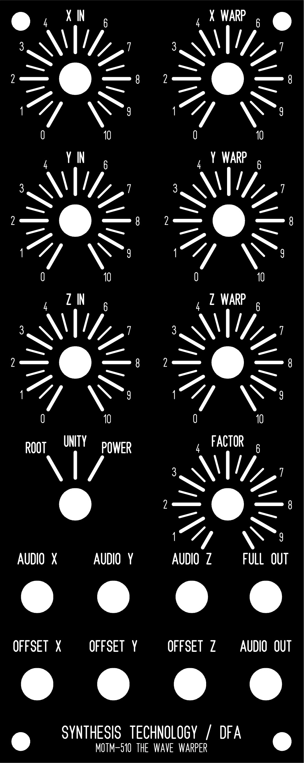
We developed this MOTM 510 panel using Front Panel Express. Click here to download our FPD file - click on the image to download a bigger one.
We approximated the Alternate Gothic No.2 font by altering the width of the "DIN451-1 stroke" font. |
|
|

|
The fine Print: Use this site at your own risk. We are self-proclaimed idiots and any use of this site and any materials presented herein should be taken with a grain of Kosher salt. If the info is useful - more's the better. Bill and Will © 2005-2011 all frilling rights reserved
|