Bill and Will's Synth
|
Background - The MOOG Schematic |
|
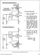
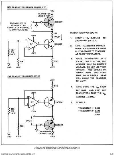
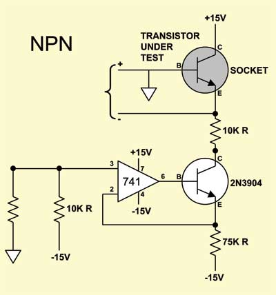
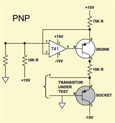
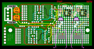
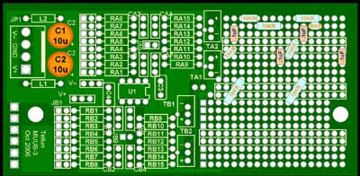
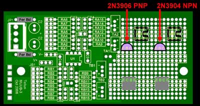
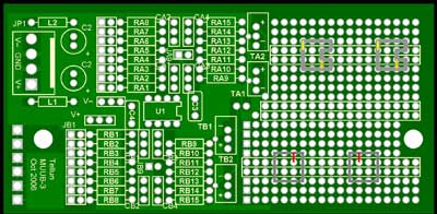
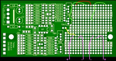
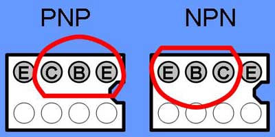
Here's the Schematic Diagram from the Mini Moog manual - click on the image for a larger version. It's set up for 10V power supply and it has a mistake in the PNP diagram. Here's the adaption for 15V and our correction of the PNP diagram. Here's how we laid it out on the MUUB3: |
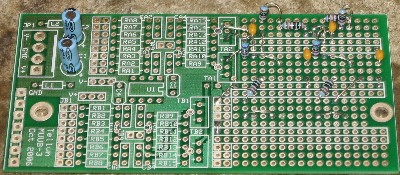
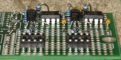
Construction Phase 1All the stuff in Phase 1 gets soldered using "Organic" Solder. At every break in the action, we wash the board off to get rid of the flux. |
|
Jumpers |
|
|
|
Resistors & Caps |
|
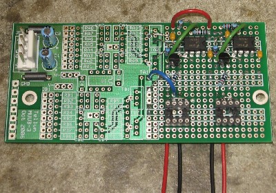
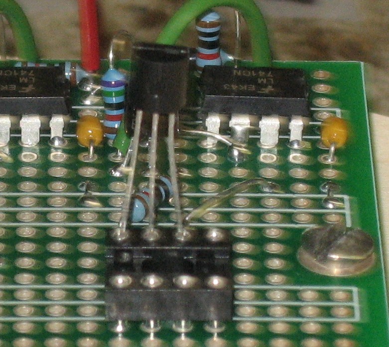
Semiconductors, Sockets, Power Stuff |
|
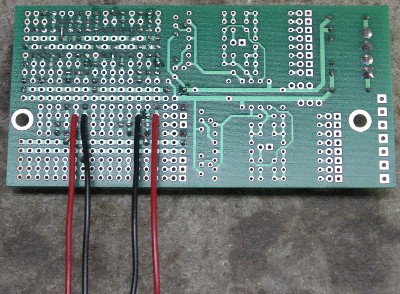
Bottom Jumpers |
Construction Phase 2All the stuff in Phase 2 gets soldered using "No-Clean" Solder and the PCB doesn't get washed off from here on. |
|
Wires |
|
Mounting the PCB |
|
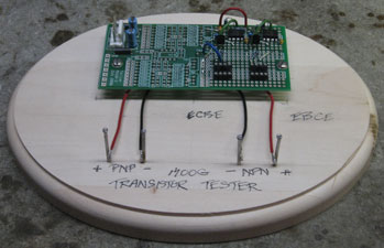
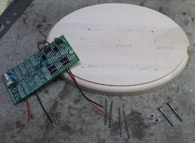
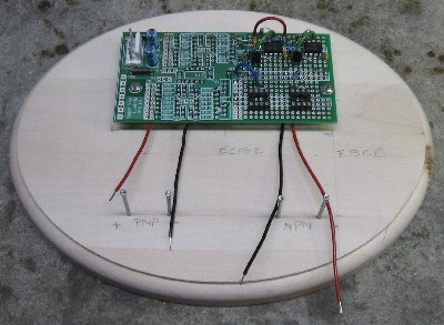
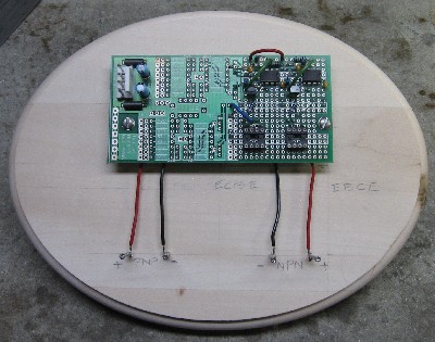
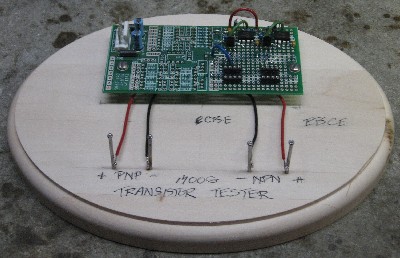
We decided to use a little plaque we found at a craft supply store as a base to mount the PCB on. We put finishing nails in the base to make easy contact points for our Test Meter. |
|
Done with Construction |
Set up / Testing |
|
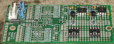
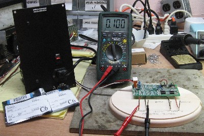
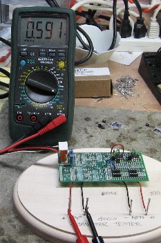
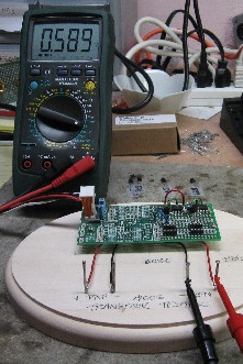
We Used our Digital Test Meter to test the thing. It has + and - 15V in the right places. The Voltage across the test points is 7.5V and without a test transistor in the socket, there's .100 milliamps (that's 100 micro amps or 100µA) across them - perfect! Sometimes you win. |
Use Notes |
|
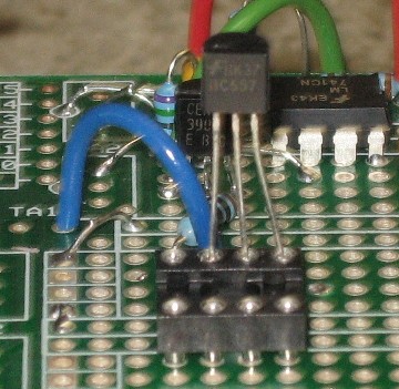
We started testing with PNP transistors and switched to NPNs. Works great! |
|
The fine Print: Use this site at your own risk. We are self-proclaimed idiots and any use of this site and any materials presented herein should be taken with a grain of Kosher salt. If the info is useful - more's the better. Bill and Will © 2005-2011 all frilling rights reserved
|
