Bill and Will's Synth
|
|
Table of Contents |
|
This documentation has become so long that we've broken it into three separate pages and sections within them. Here's a table of contents that we hope will make it easier to traverse them: Background - presents an explanation and Scott Juskiw's initial description of the module with a photo Parts - presents a Bill of Materials and notes about it Panel - presents the MOTM format panel Mounting Brackets - our use of two "Stooge" 3-pot brackets Construction PCB 1A&B - MUUB4 Construction PCB 2A&B - MUUB4 Construction PCB 3A&B - MUUB2 Construction PCB 4 - MUUB2 PCB Connections - wiring the PCBs together Panel Wiring - connecting the PCBs to the panel |
Background |
|
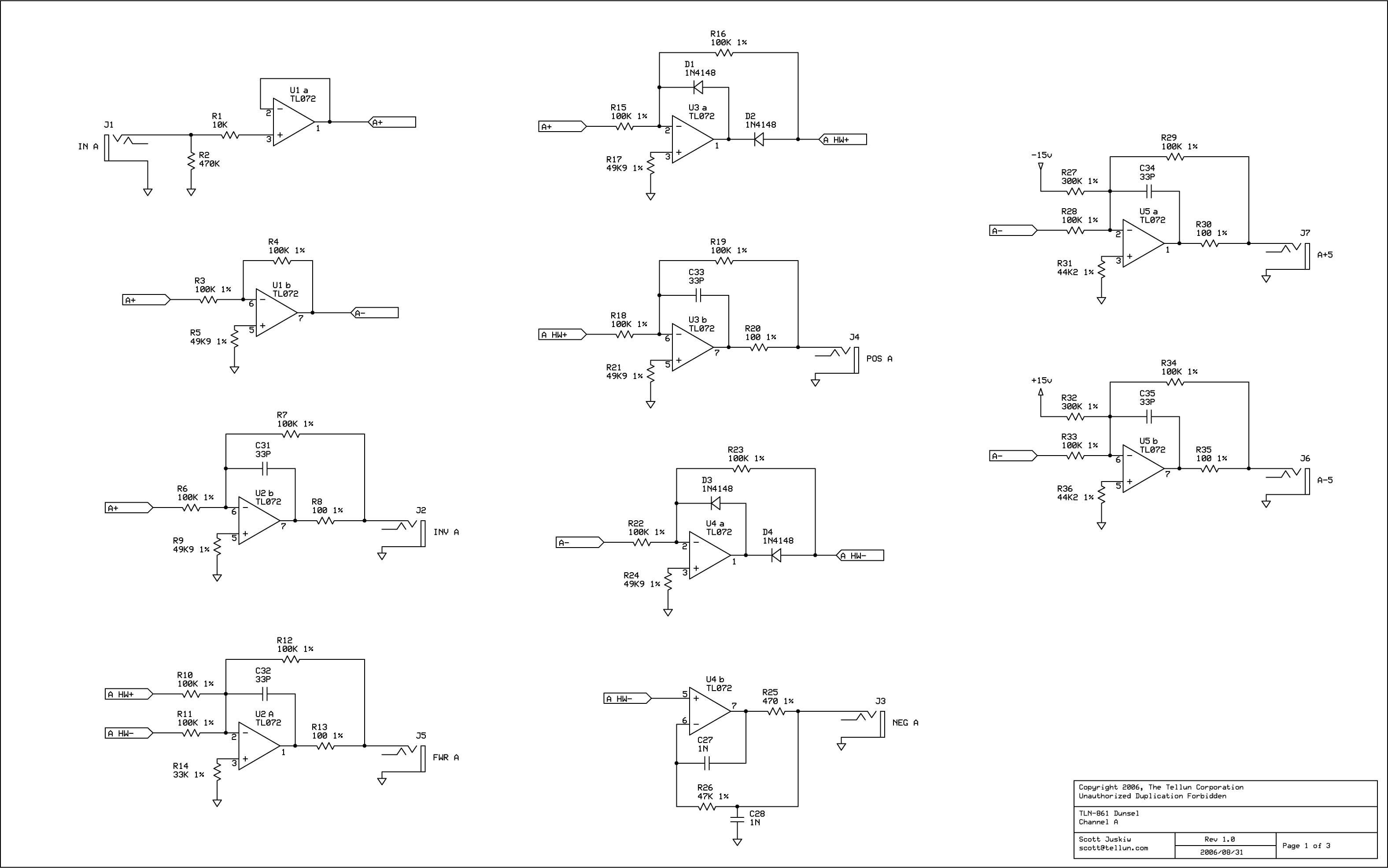
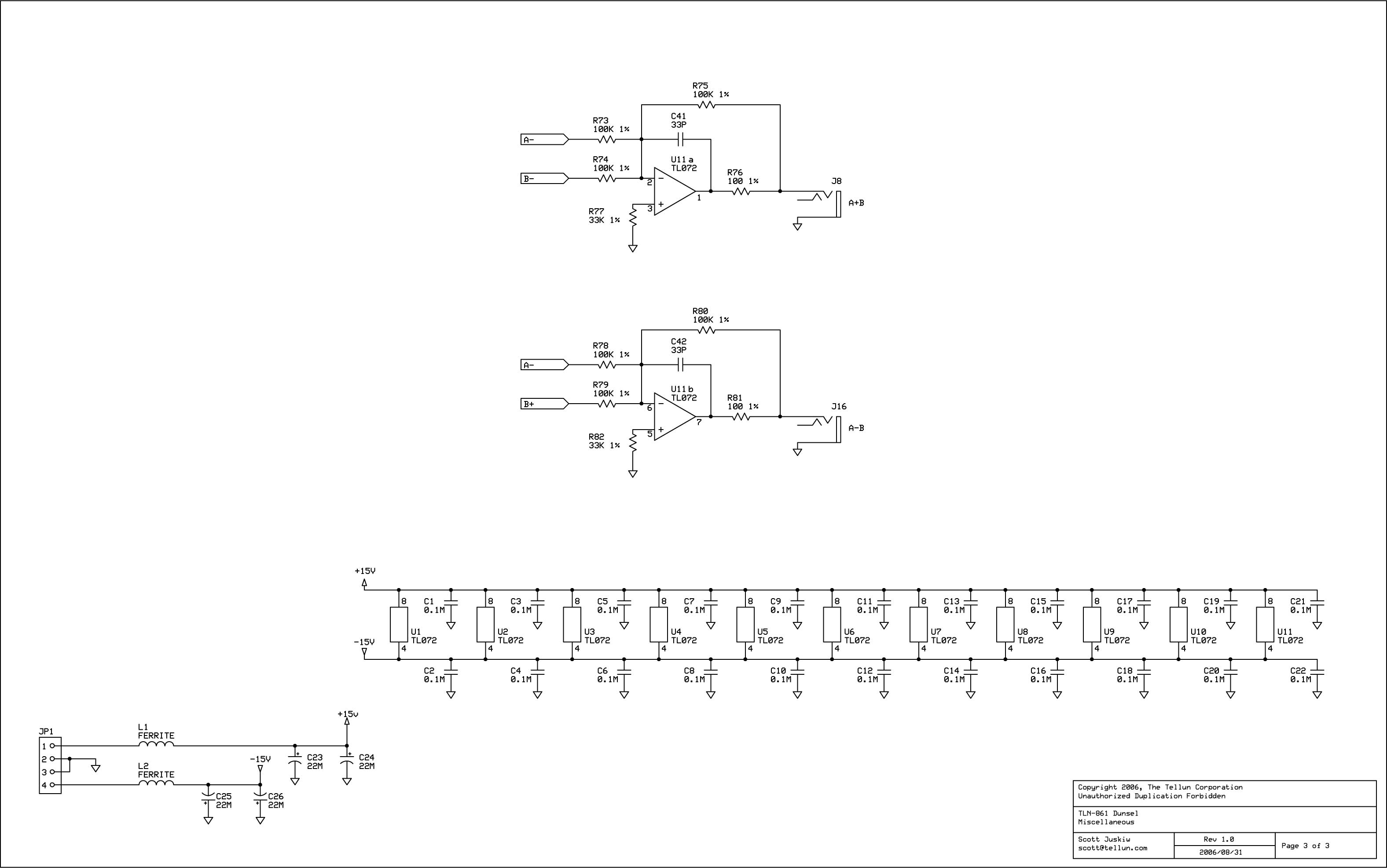
Scott writes: The TLN-861 Dunsel is a utility module that generates several commonly used signals from an input voltage. When patching my synth, I find I constantly require unity gain inverters, adders, subtractors, half/full wave recitifiers, and level shifters. While it's possible to generate these signals using MOTM-830, Oakley WaveFolder, or Oakley Multimix modules, that's not often the best use of those resources. Enter Captain Dunsel to the rescue. The Dunsel features two channels (A & B) with the following independent outputs:
The Dunsel also has the following combined outputs:
The TLN-861 Dunsel can be built using MUUB daughterboards. Total current draw for TLN-861 is 38 mA @+15V and 38 mA @-15V.
Schematics Here's Scott's Schematics (click on the images to see a high-rez version):
|
Parts |
|
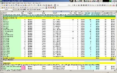
Will and I have developed a parts-list / bill-of-materials in the form of an XL spreadsheet (as usual). It's pretty complete now - we are relatively confident in our specifications.
Click here to download our XL spreadsheet Parts List |
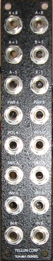
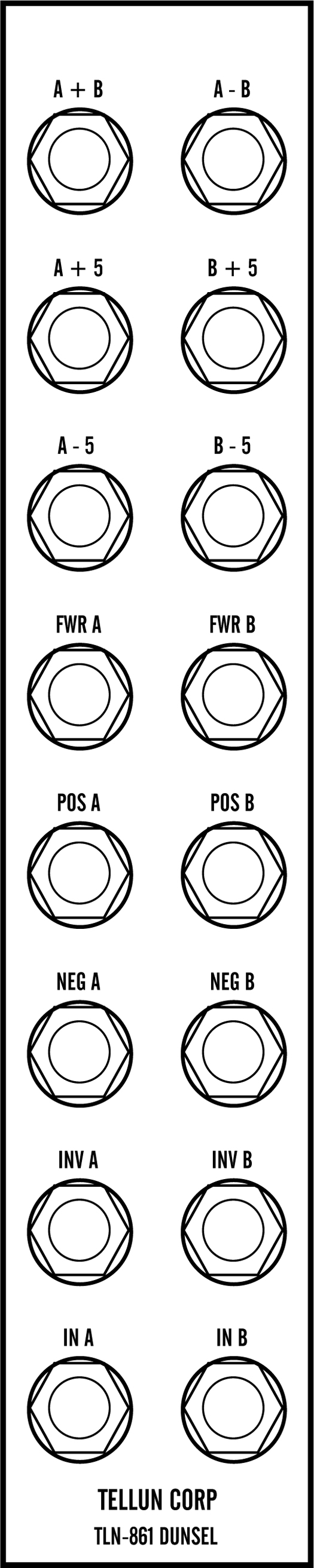
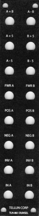
Panel |
|
We got ours at Bridechamber.
|
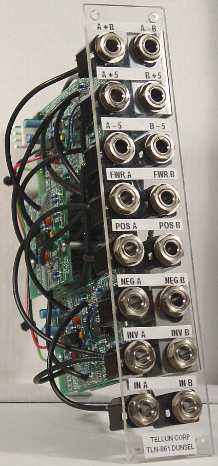
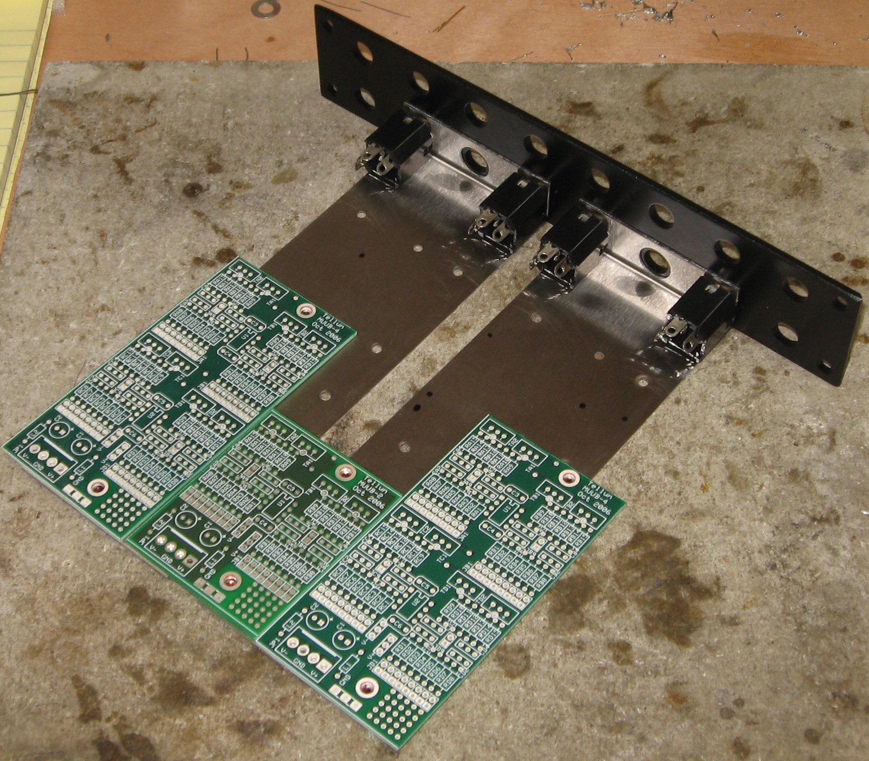
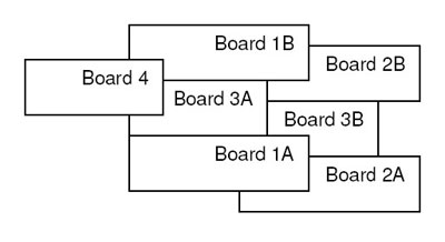
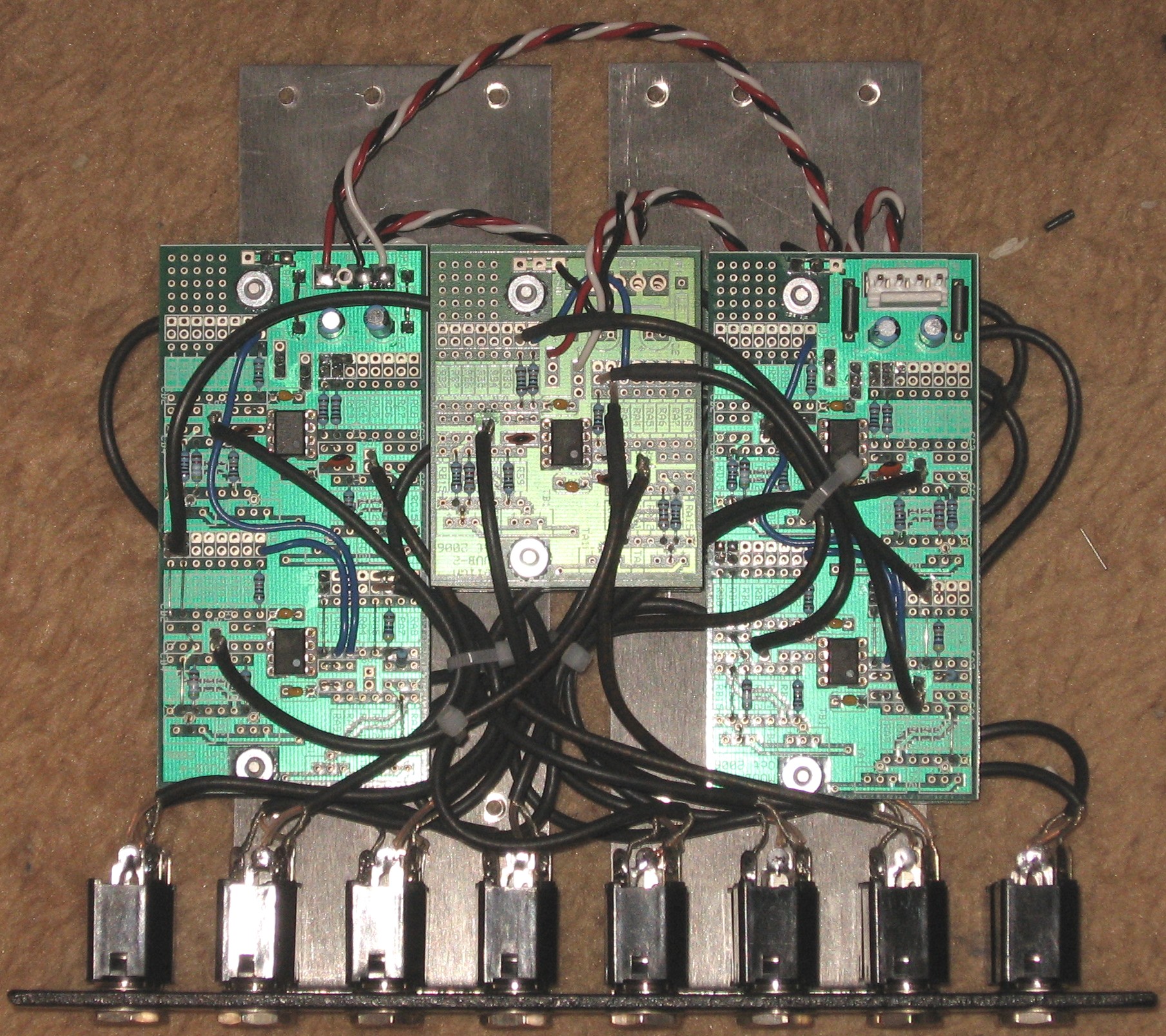
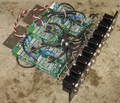
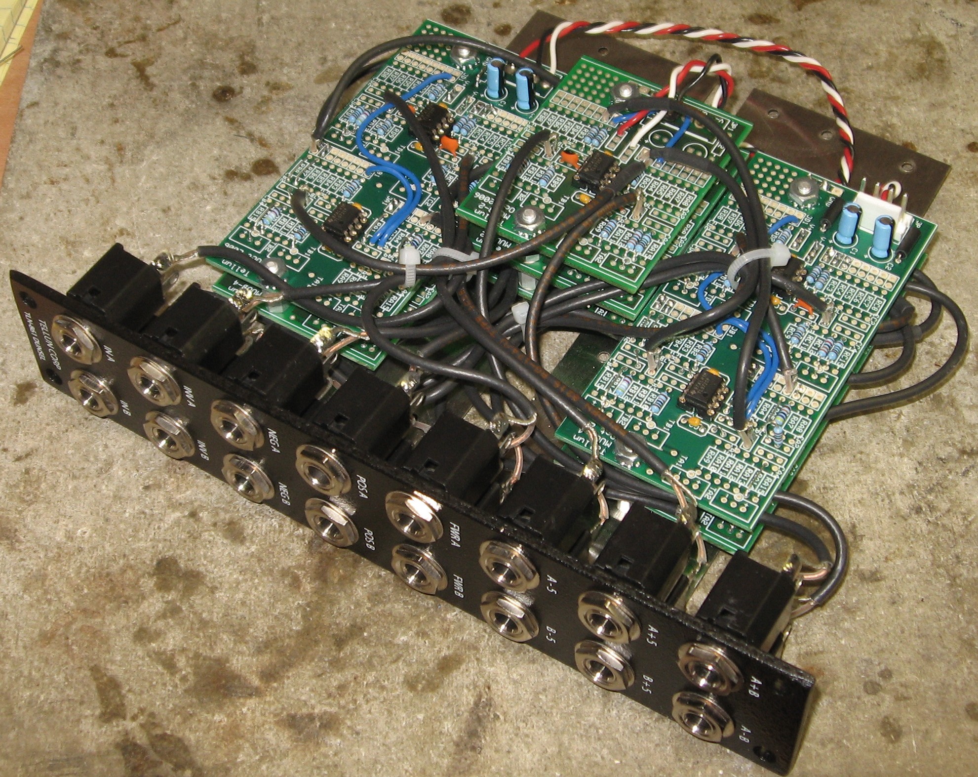
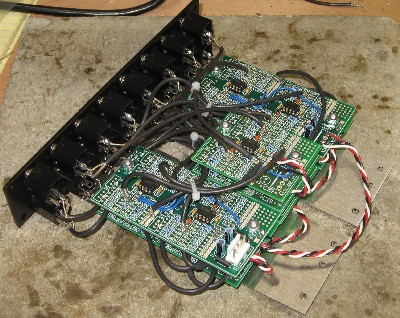
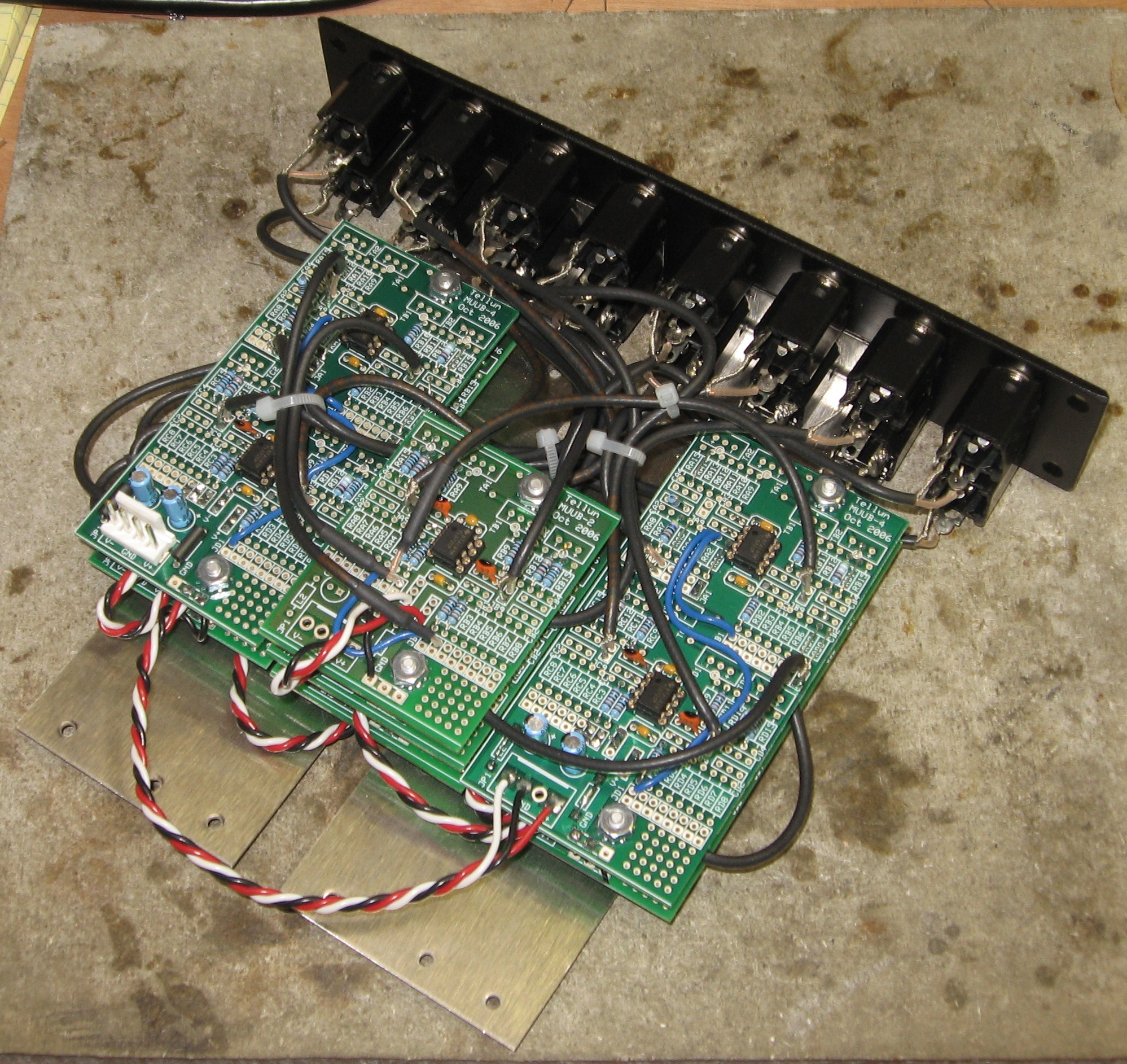
Mounting BracketsScott urges assembling the pcb brackets and the panel first. We figured out that two of the Bridechamber three-pot mounting brackets would do the trick like this:
We marked the brackets for drilling, drilled the holes, and thought we had done well. It wasn't until later that we realized that with the PCBs at this distance from the panel, we needed to increase the length of the PCB-to-Jack wires by 2-1/2 inches (foolish of us, yes) so we re-drilled the brackets so the PCBs are right close to the jacks. But if you're doing it this way, please consider making the wires longer and keeping the PCBs away from the panel (assuming your cabinets will allow the depth) because it'll give you more room to maneuver as you're soldering up the jacks. |
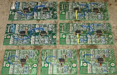
Construction / Connections |
|
Go on to Page Two - MUUB Construction
Go to Page Three - Connections
|
|
|
|
And now, back to work. |
Construction Done
|
Set up / Testing |
Use Notes |
|
|

|
The fine Print: Use this site at your own risk. We are self-proclaimed idiots and any use of this site and any materials presented herein should be taken with a grain of Kosher salt. If the info is useful - more's the better. Bill and Will © 2005-2011 all frilling rights reserved
|