Bill and Will's Synth
|
||
Table of Contents |
||
|
This page has become really long, so here's a table of contents that we hope will make it easier to traverse: Background - presents an explanation and Tim Parkhurst's initial description of the Module with a photo Options - presents details of the different possible implementations Modifications - presents details of possible modifications Parts - presents a Bill of Materials and notes about it Panel - presents the MOTM format panel Construction Phase 1 - Resistors, Capacitors, IC Sockets, Power Plugs, MTA headers Construction Phase 2 - Trimmers, Tube, Panel connetcions |
||
Background - Ken Stone's Design |
||
|
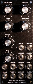
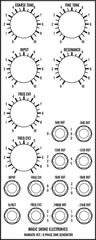
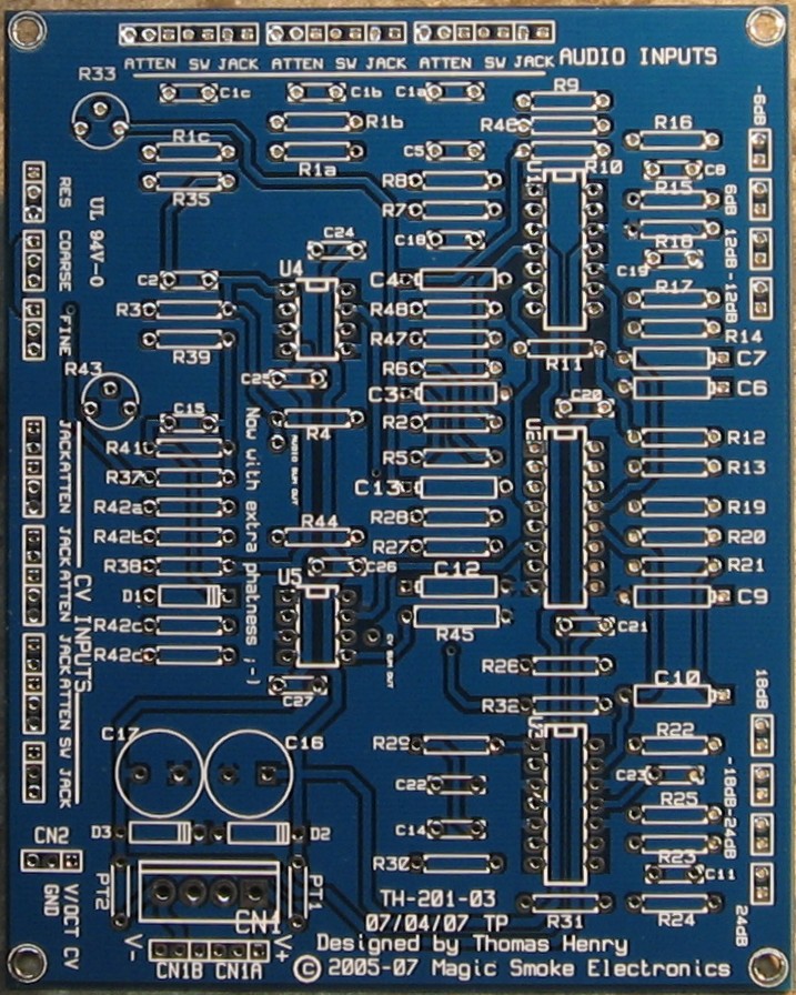
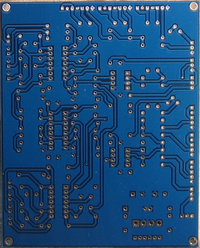
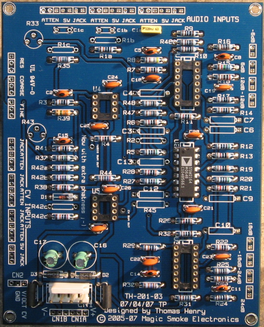
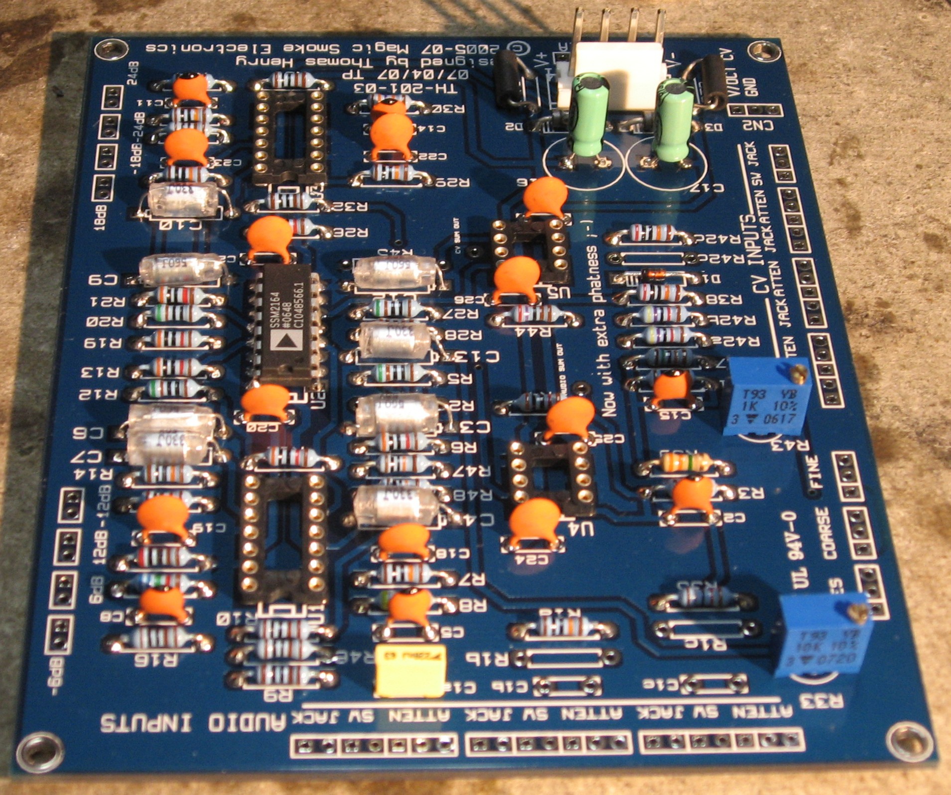
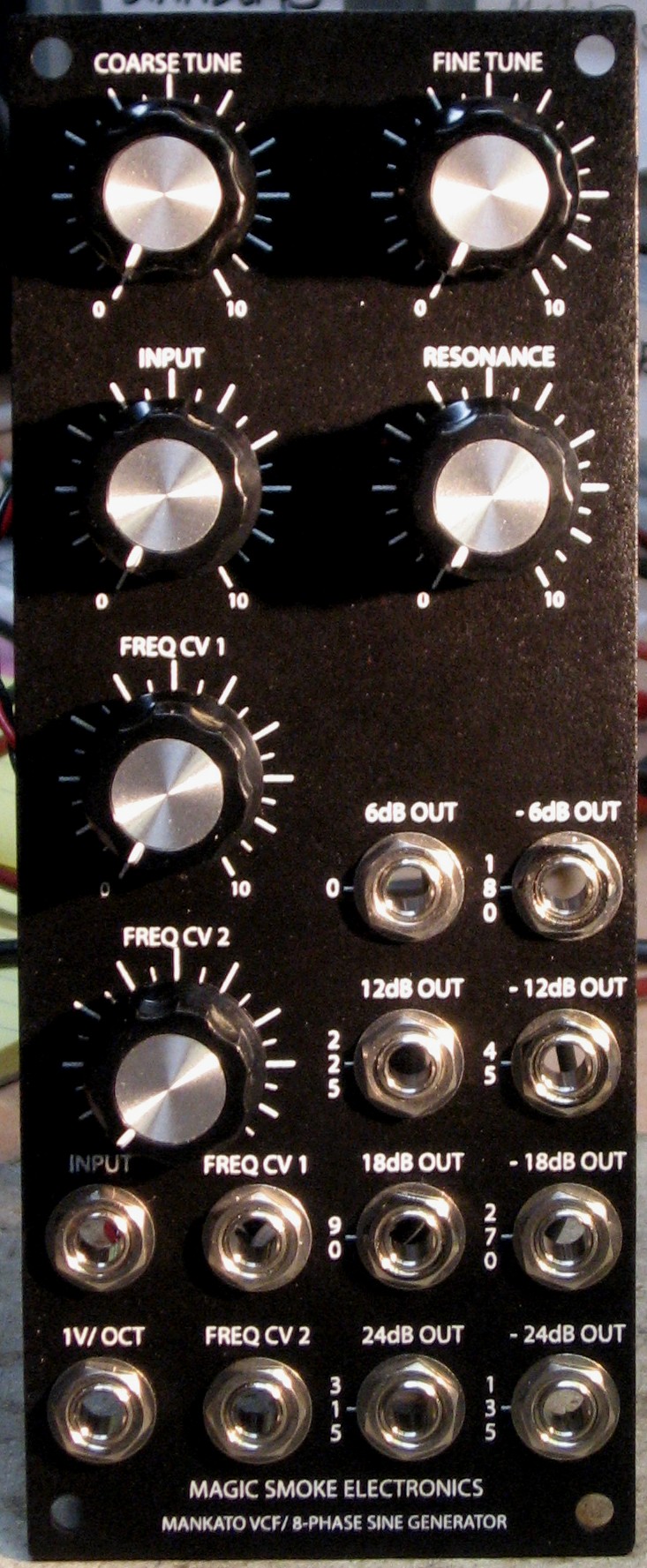
Here's what Tim Parkhurst of Magic Smoke Electronics says about the Mankato: "Designed by well known synth DIY guru Thomas Henry, the TH-201 is a low-pass VCF with some unusual operating modes. Magic Smoke will be producing printed circuit boards (PCBs) which can provide up to eight outputs. With the Resonance control turned all the way up, these filters will self-oscillate, operating as multi-phase LFOs or VCOs. "Both DC-coupled and AC-coupled inputs are available. The DC-coupled inputs allow the TH-201 to operate as a voltage-controlled lag processor (slew limiter). All outputs are buffered and have standard 1k impedance. "The Mankato covers a very wide frequency range -- around 0.005Hz (200 seconds/cycle) to beyond 20kHz without range switches. Changing the timing capacitors can provide extended low frequency operation. You can certainly build your Mankato with a range switch, if that's your preference."
|
||
Options |
||
1. R2 - SSM2164 Bias Mode |
||
|
The SSM2164 chip has two options - it can be run in "AB" mode or in "A" mode when R2 is installed. We're not sure yet what this really means.
|
||
2. Inputs |
||
|
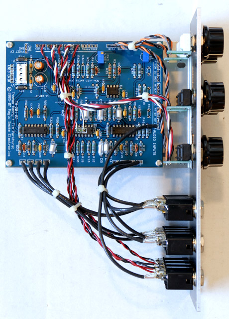
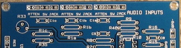
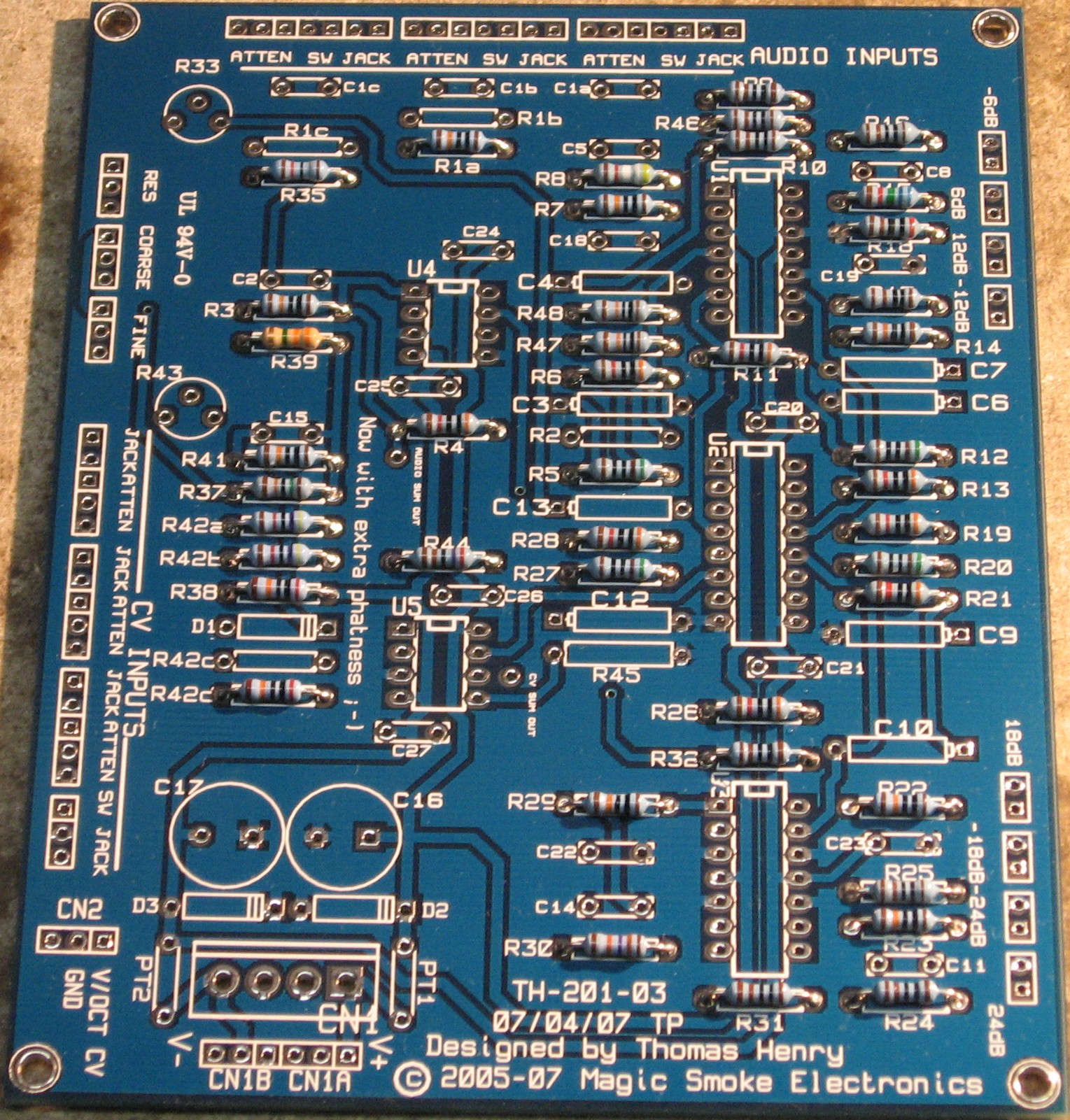
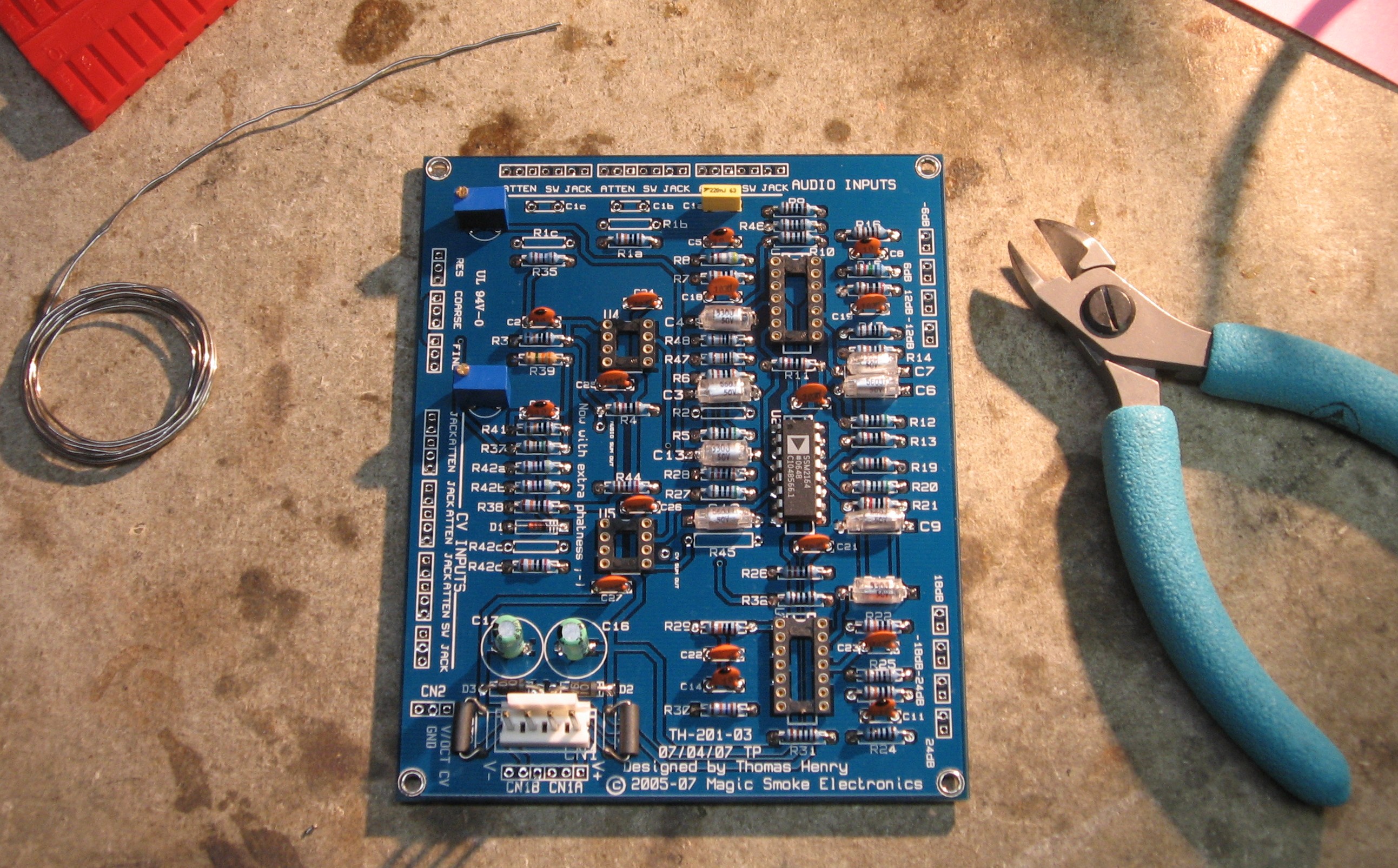
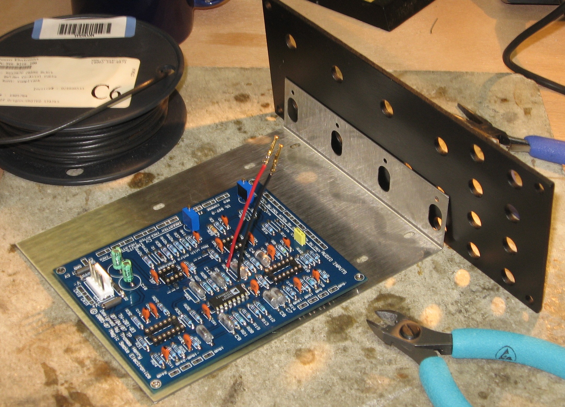
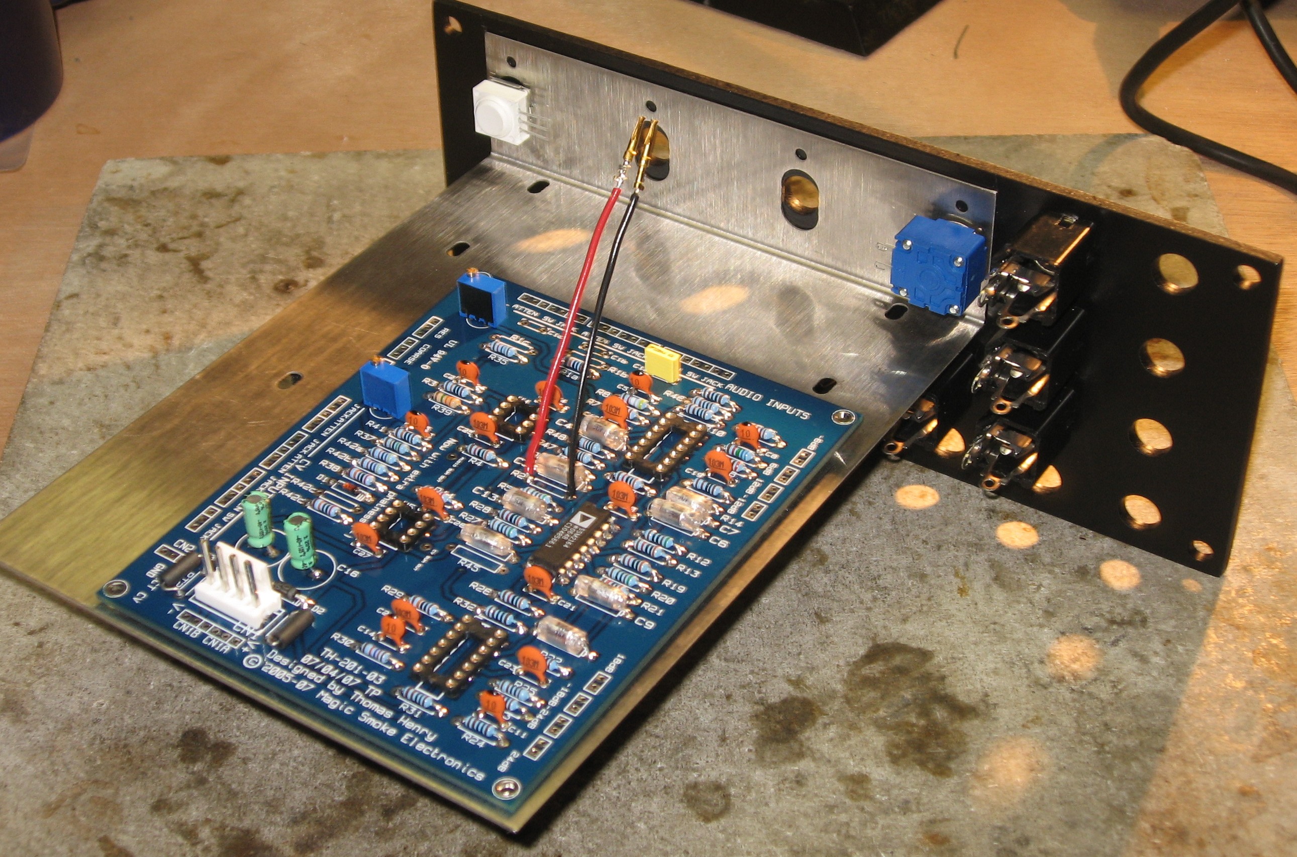
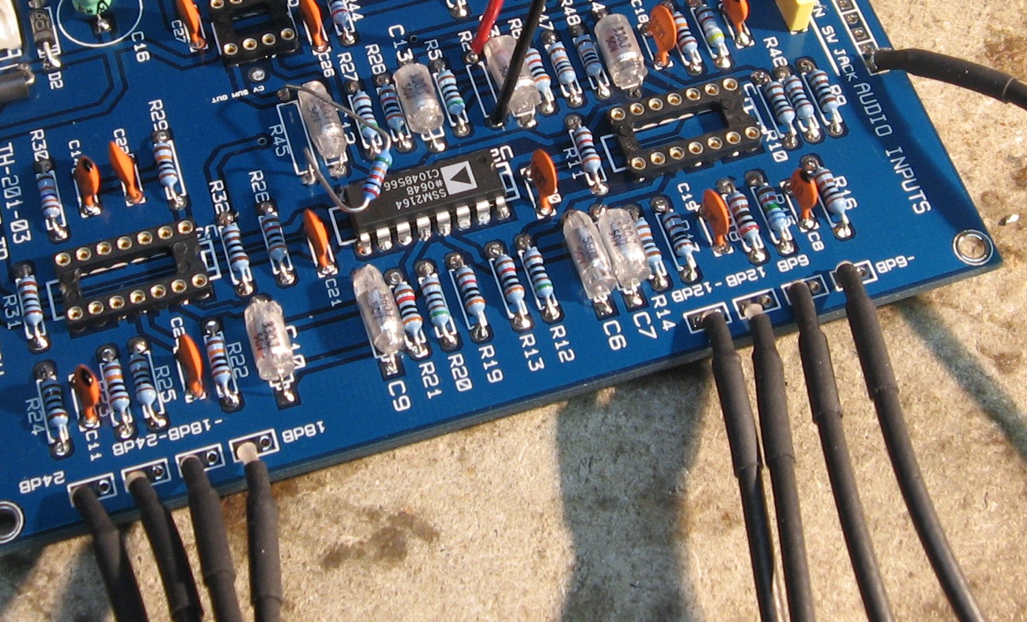
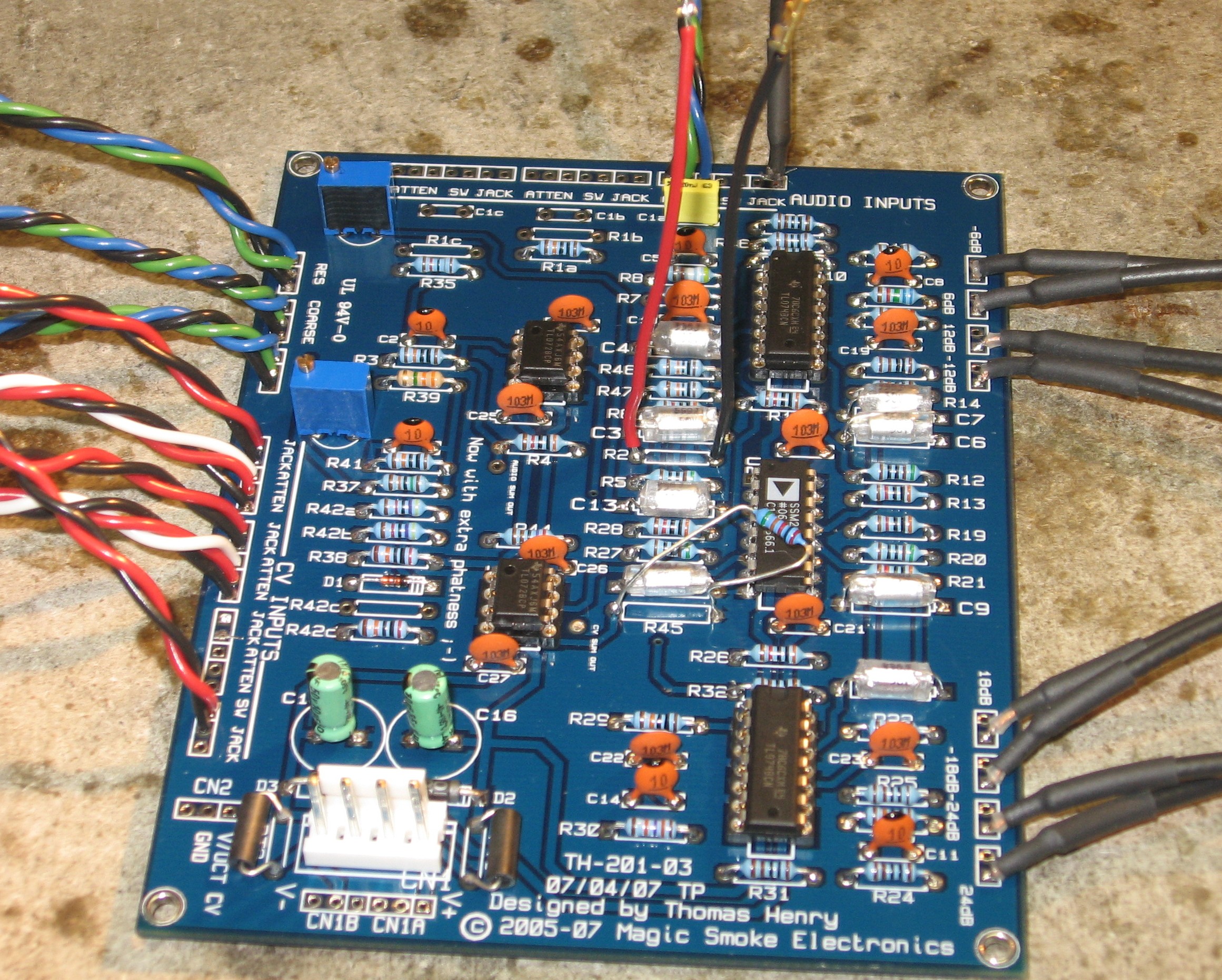
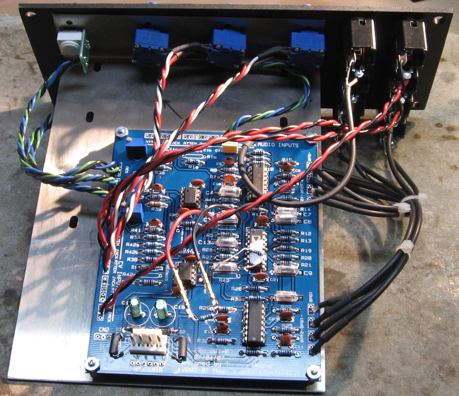
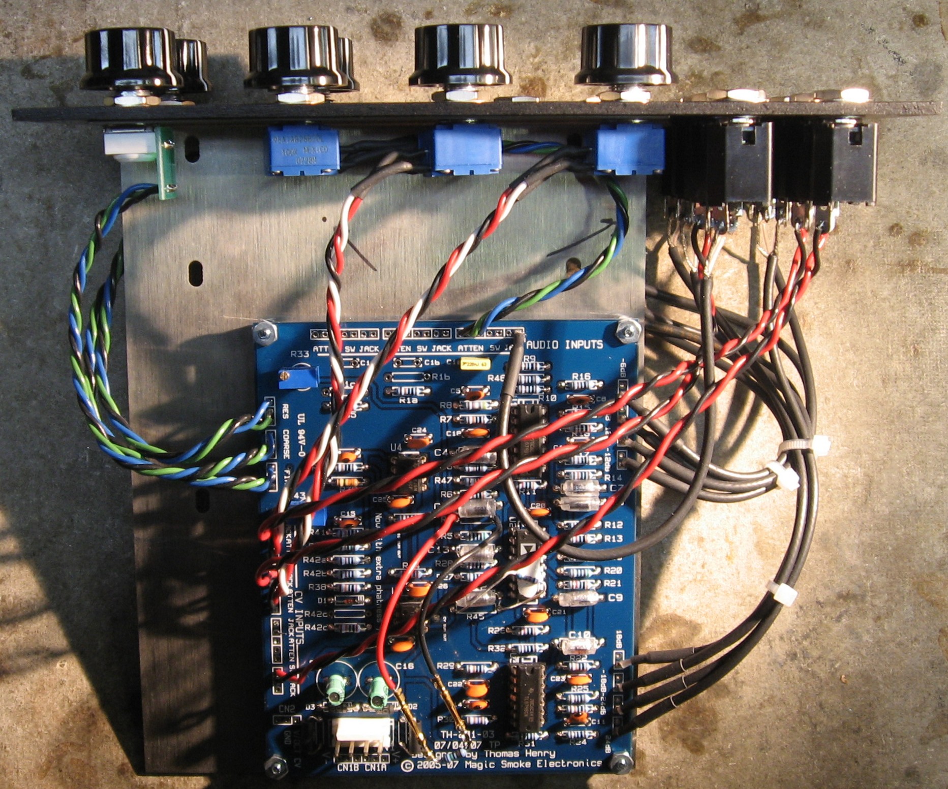
Audio The "Mankato" PCB has three possible audio inputs, we're only going to use one and so we'll install only R1a and C1a and use the right-most "JACK" and "ATTEN" Audio connections (rightmost in the photo below).
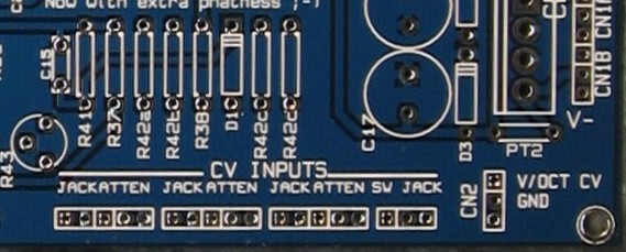
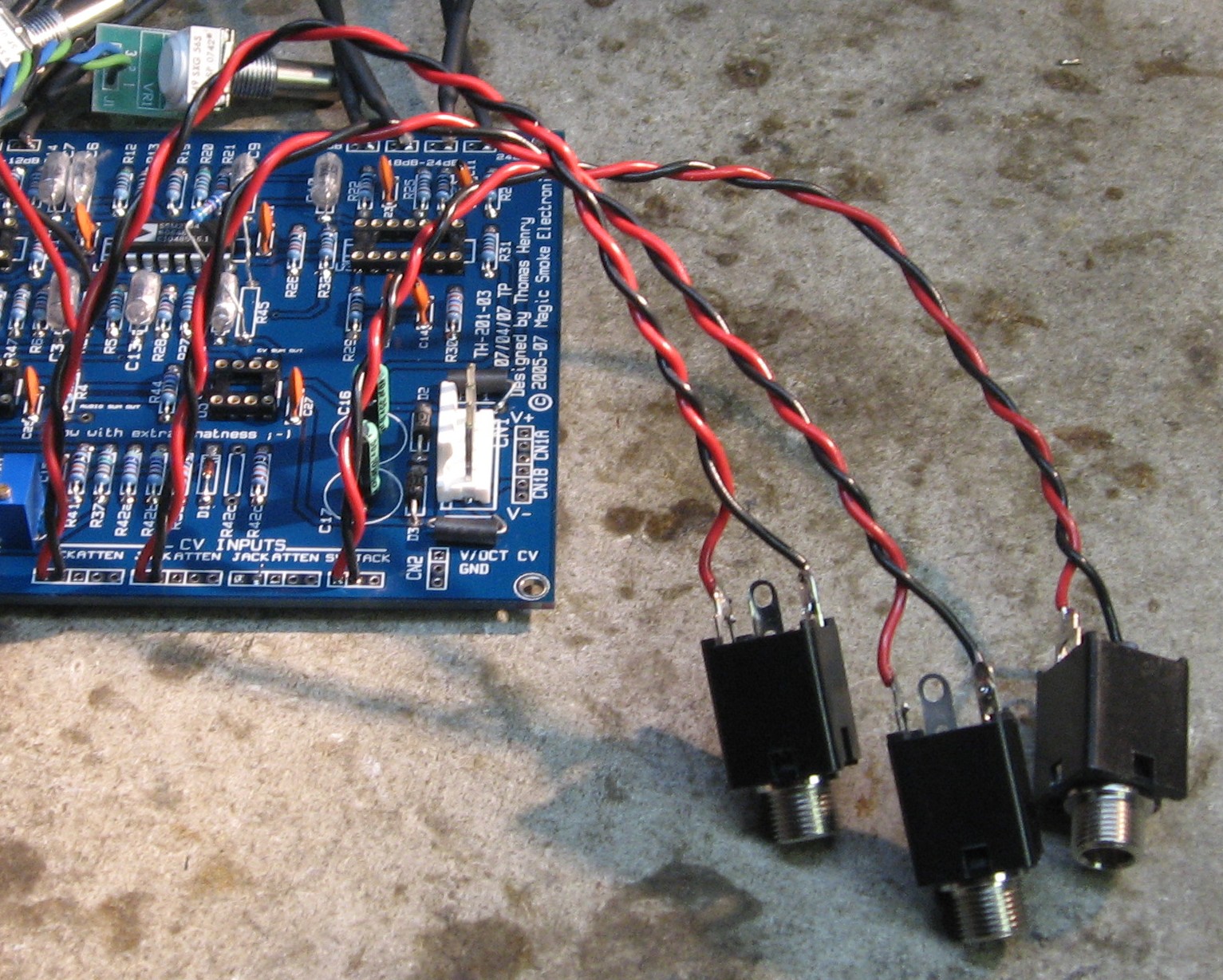
Control Voltage - FREQ CV 1 & 2 The "Mankato" PCB has three possible CV inputs, we're only going to use two and so we'll install only R42a and R42b and use the top two "JACK" and "ATTEN" CV connections (leftmost in the photo below). Control Voltage - V/OCT Just for clarity, the volt per octave connection will be made at the lowest "JACK" CV Input position (rightmost in the photo below) and therefore R42d will be installed as always.
|
||
Modifications |
||
1. Coarse and Fine Pots |
||
|
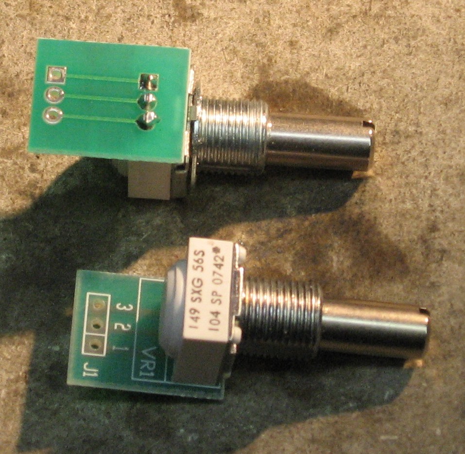
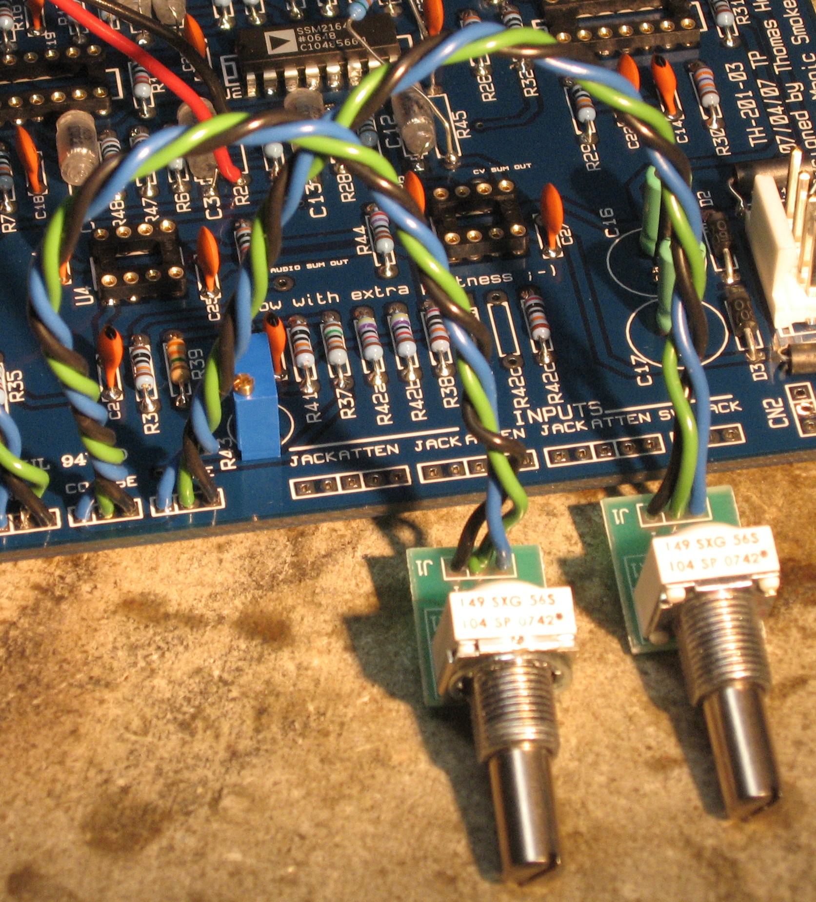
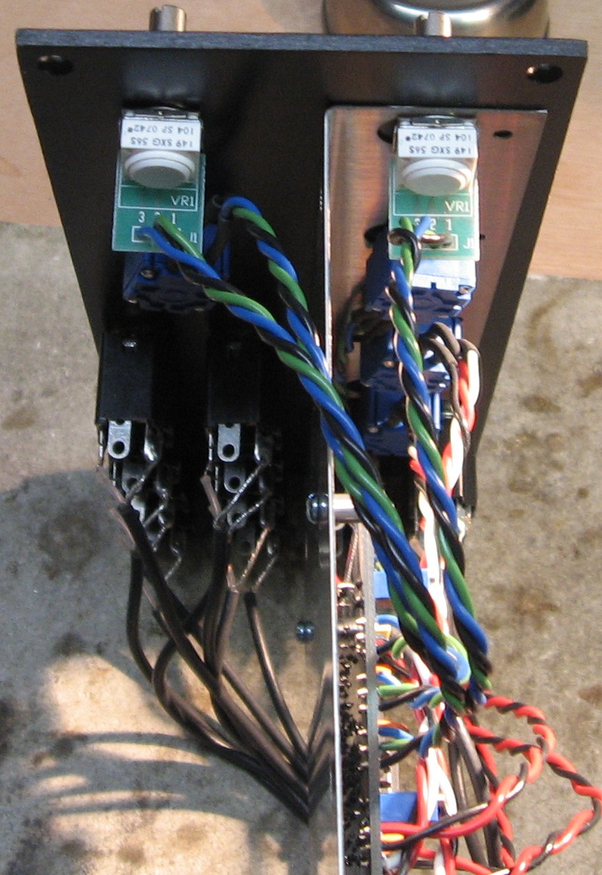
Following Dave Brown's implementation for greater temperature stability, we used Spectrol 149 cermet pots for the Coarse and Fine panel controls instead of conductive plastic. (Mouser Part# 594-149-7104) |
||
Parts |
||
|
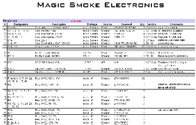
Will and I used the Bill of Materials from the Magic Smoke Electronics site. We found everything at mouser just fine, but we got the tempco resistor from Bridechamber where you can also find the SSM2164 chip. We got ours from digikey back before Bridechamber had them.
Click here to a copy of Tim Parkhust's BOM. |
||
Panel |
||
|
We got ours from Bridechamber:
|
||
Construction Phase 1All the stuff in Phase 1 gets soldered using "Organic" Solder. At every break in the action, we wash the board off to get rid of the flux. |
||
|
|
||
|
Resistors |
||
|
As usual, whereas we are vigilant about orienting all the resistors, caps, etc. consistently so their values can be read easily (in case we need to trouble-shoot them later), we oriented the resistors with the "tolerance" stripe on the left (relative to the text on the pcb). We got started doing it this way when we started building our synth and now we do it so all our modules are consistent with each other. You might want to do it the opposite way - with the "tolerance" stripe on the right. |
||
|
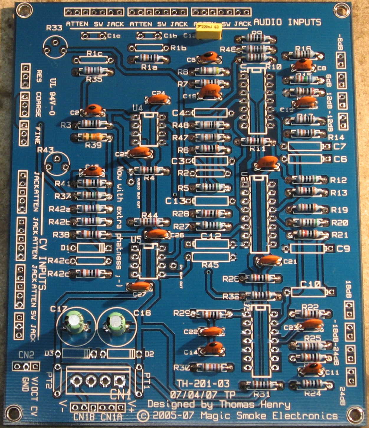
Capacitors |
||
|
Notes:
|
||
|
ICs - Misc Stuff |
||
|
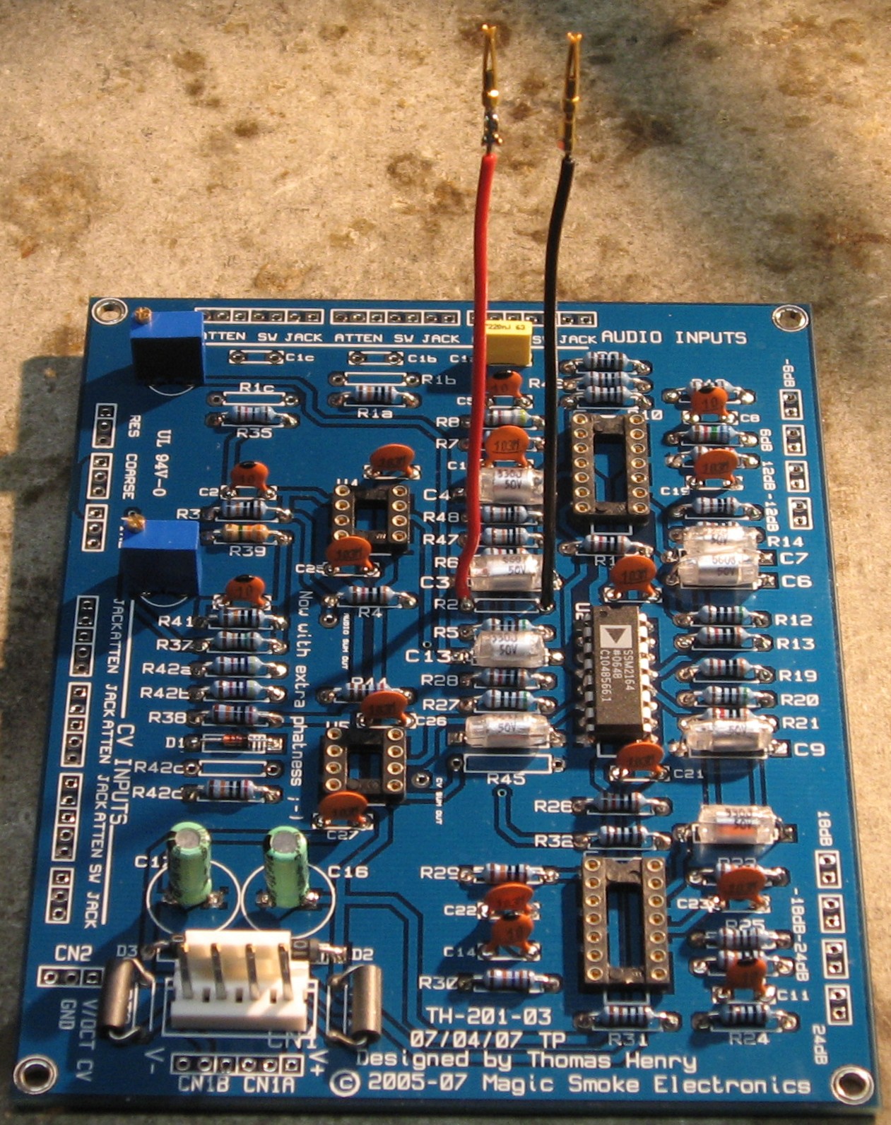
We had a few dozen regular old TL072CN & TL074CPs, but not the "B" variety. So we soldered IC sockets where those should go. We figured we'd use regular old TL072 & 4s and when we find the "B"s we could plug them in. But we found the SSM2164 just fine and soldered it directly into the board which is good because that's where we're going to heat sink the tempco resistor. Of course then we found the TL072B and TL074B. <sigh> <shrug> |
||
|
||
Construction Phase 2All the stuff in Phase 2 gets soldered using "No-Clean" Solder and the PCB doesn't get washed off from here on. |
||
|
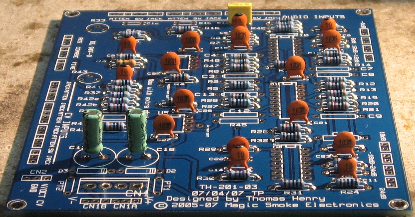
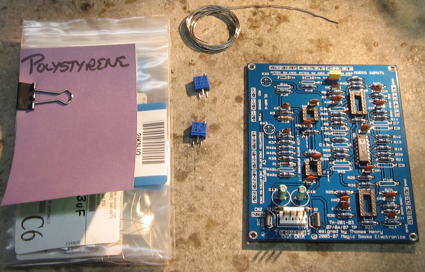
Trimmers - Polystyrene Caps |
||
|
| ||
|
R2 - Setting the SSM2164 Bias Mode |
||
|
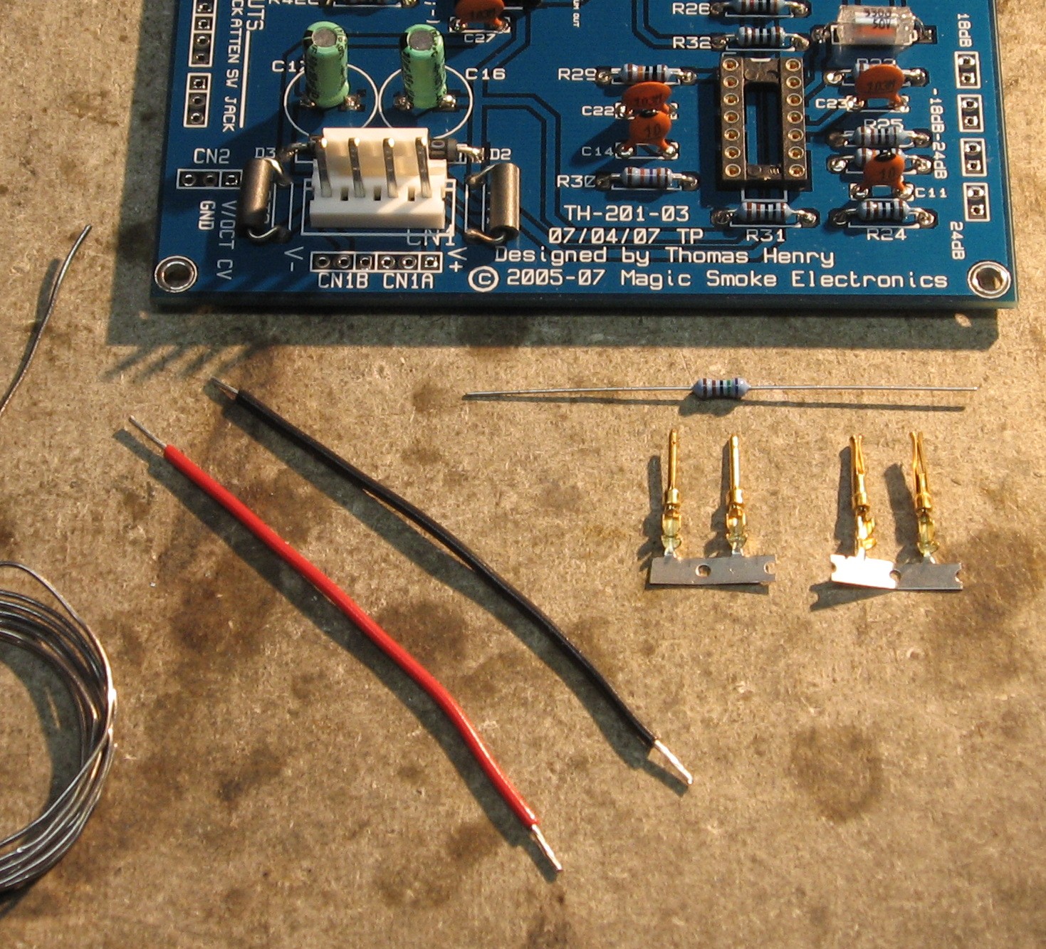
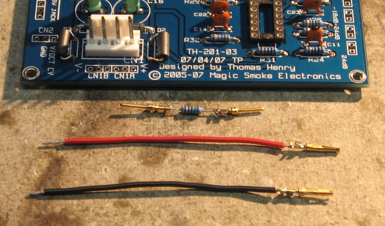
We're going to install little leaders with the great little pins and sleeves Gino Wong gave us on the 7.5K resistor for R2. We'll go ahead and install R2, then, so the SSM2164 chip will be in "A" bias mode. If we don't like it, we can pull the resistor out. At this point we didn't even know how to make a judgement about it because we don't really understand the sonic implications of the two modes "AB" or "A". But this keeps our options open.
Normally, we'd solder in the 2K tempco resistor in at this point, but it was still on order from Scott Deyo. So we figured we'd go on to other things while we're waiting. |
||
|
Bracket Layout |
||
|
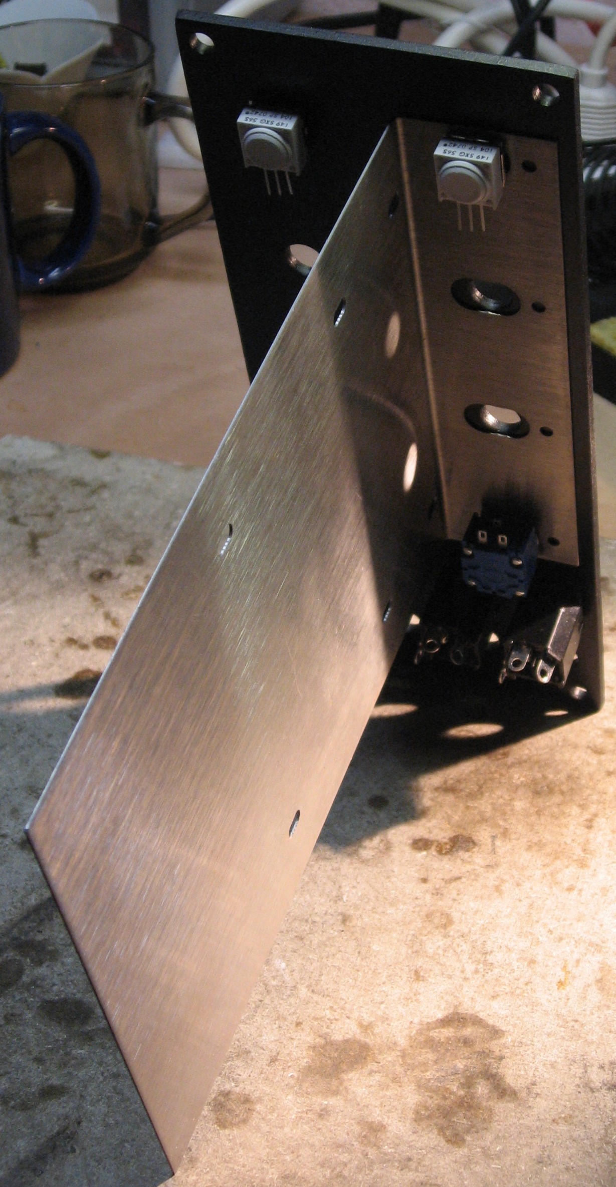
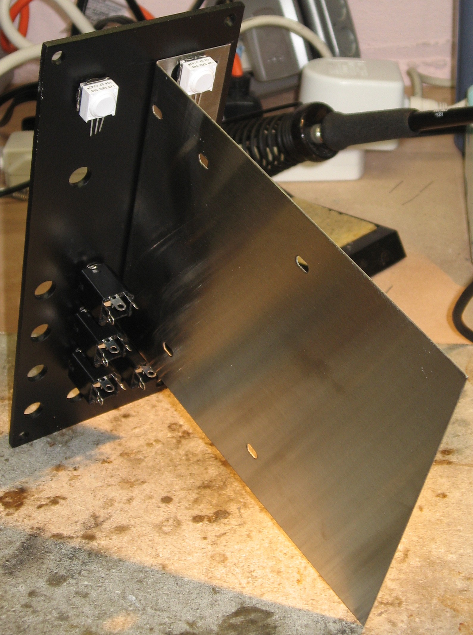
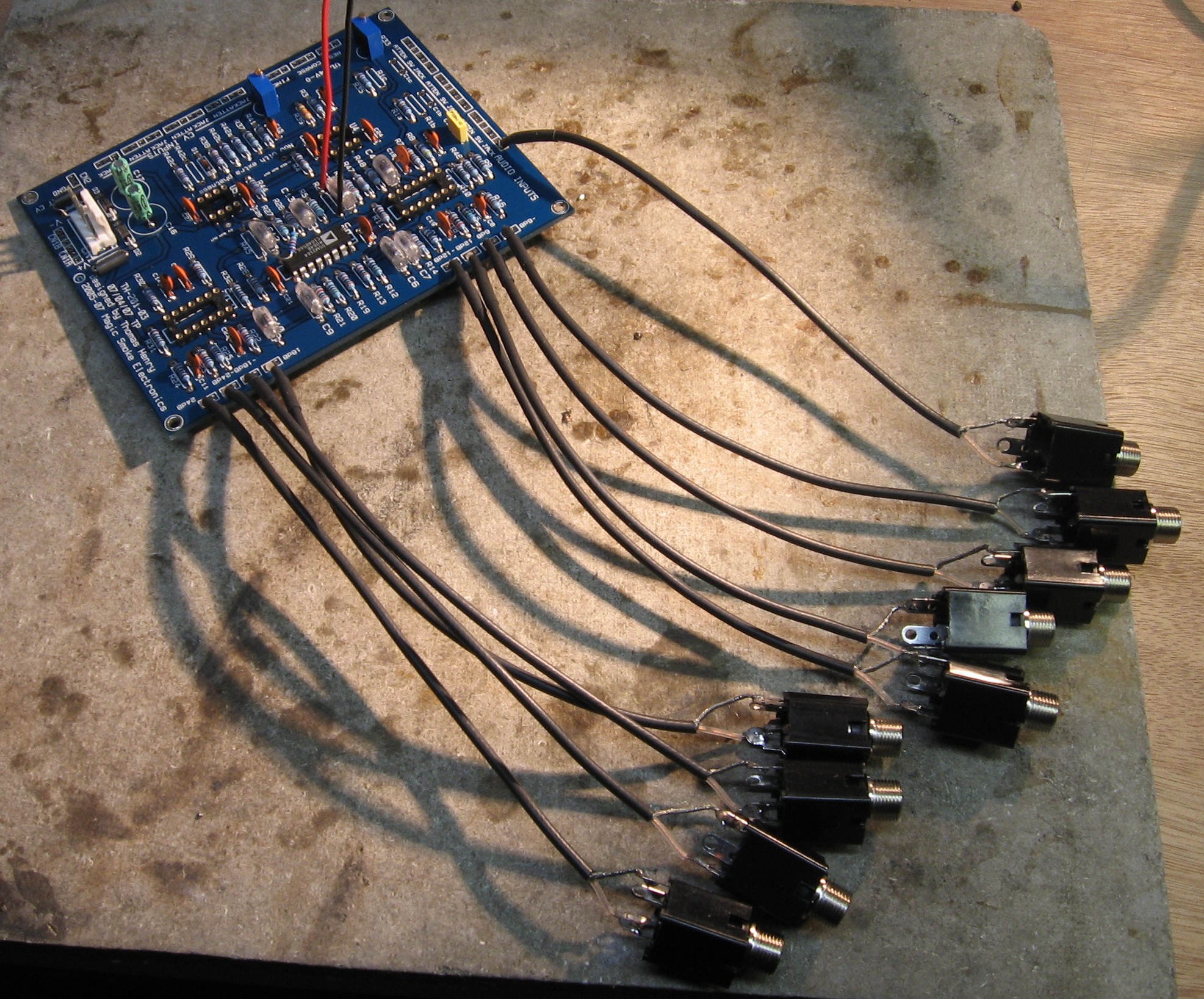
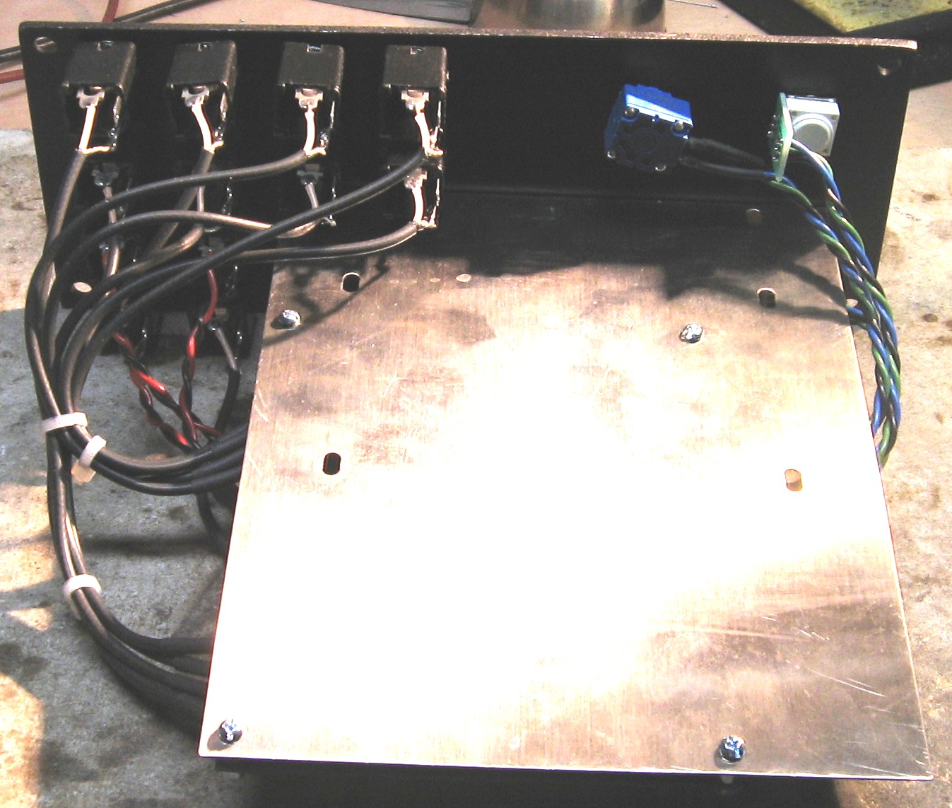
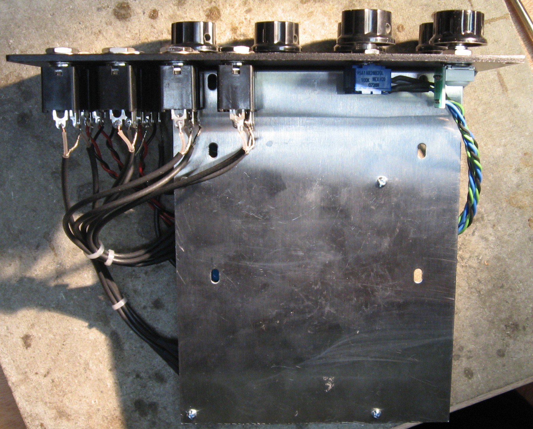
We took a look at how the pcb mounting bracket would attach to the panel so we can decide lengths of connecting wires.
It posed an interesting issue. If we mounted it like we usually do - per MOTM convention on the extreme left of the panel (when viewed from the back) - we'd have to cut off the bottom two pot holes. What if we did an unconventional mounting scheme?
This is how we decided to do it. This layout still places the power connector in the traditional position and it should be very stable because we can use all four pot holes to hold it on. Because of the close quarters around the bracket, we decided to connect up all the pots and jacks to the wires first - and then install them into the panel. We started considering how long the ouput coax should be to get to the output jacks. | ||
|
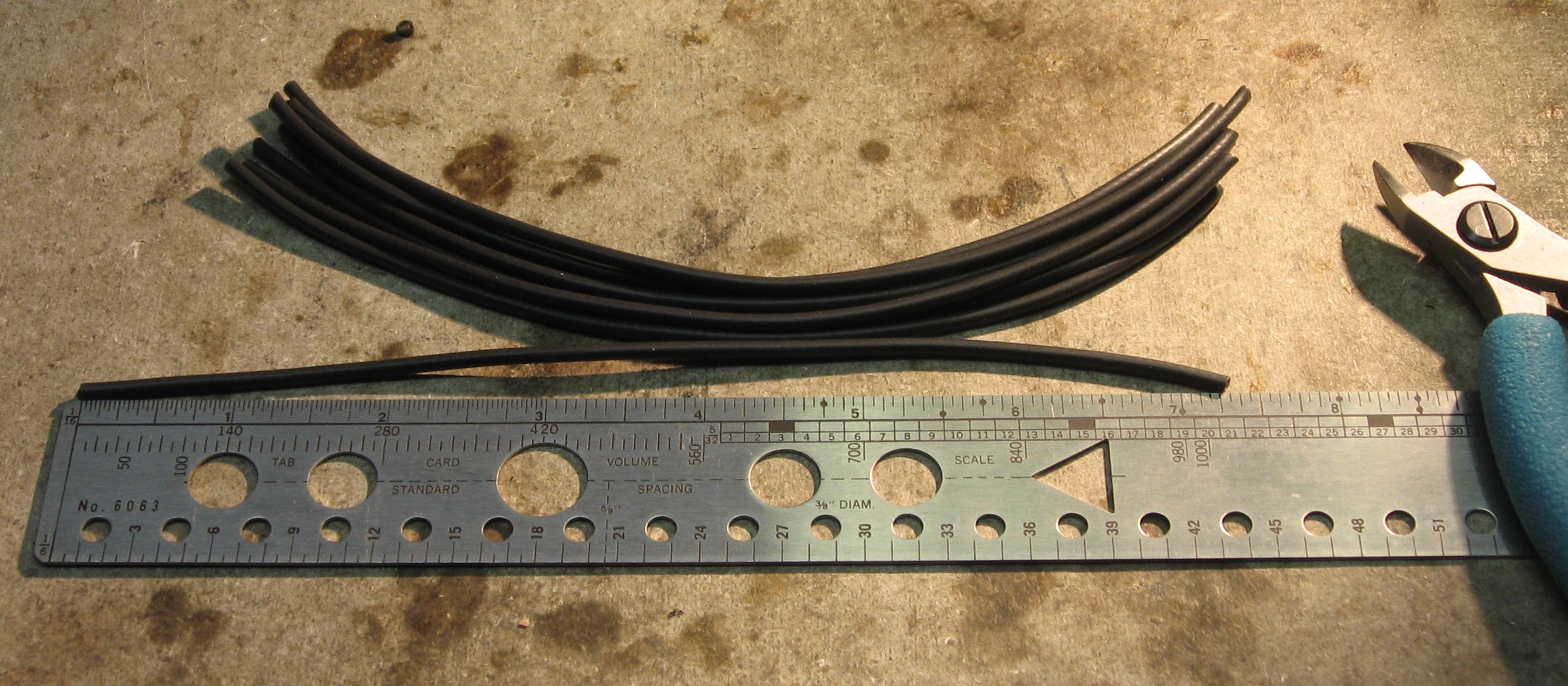
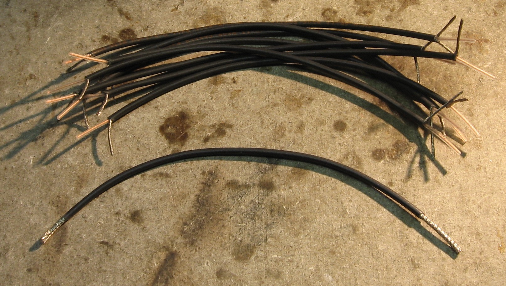
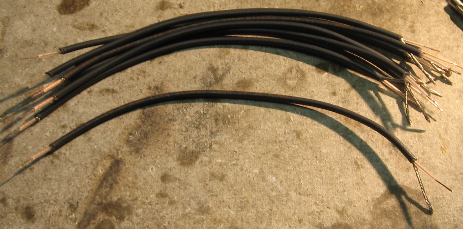
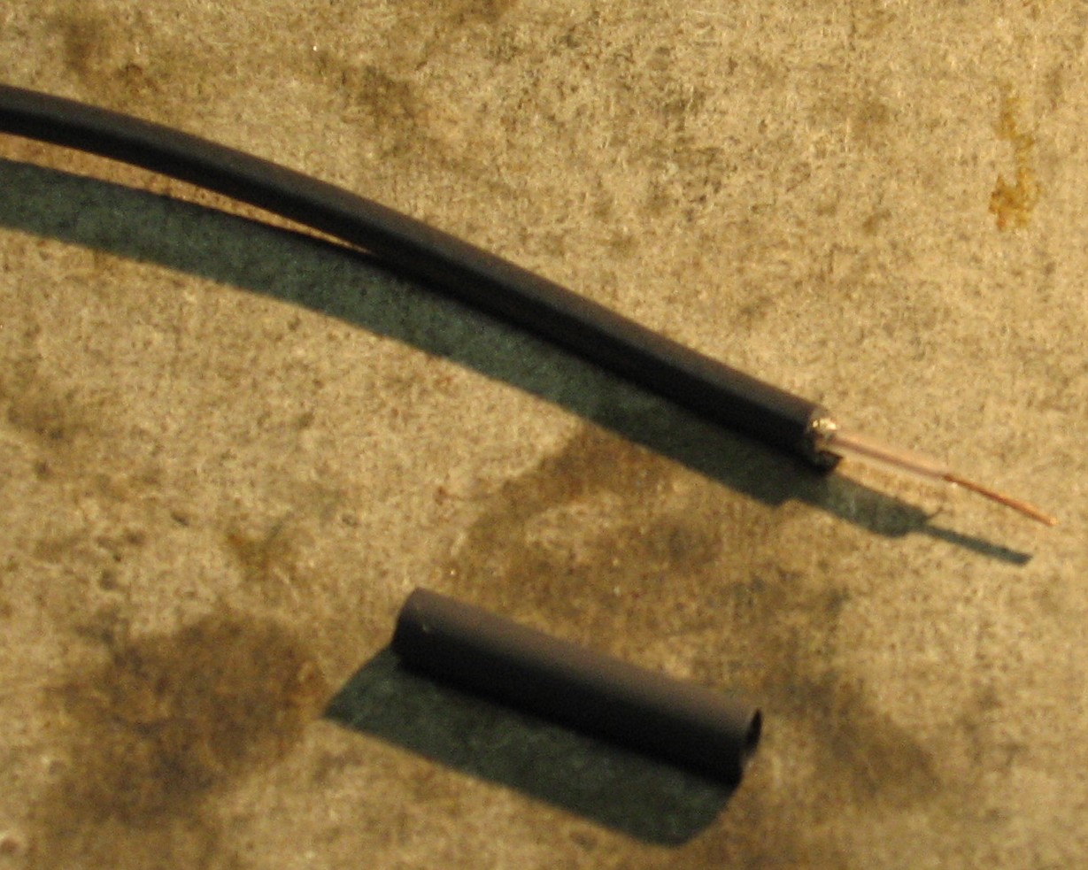
Prepare Coax |
||
|
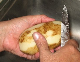
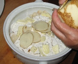
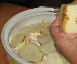
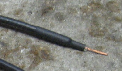
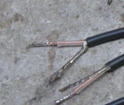
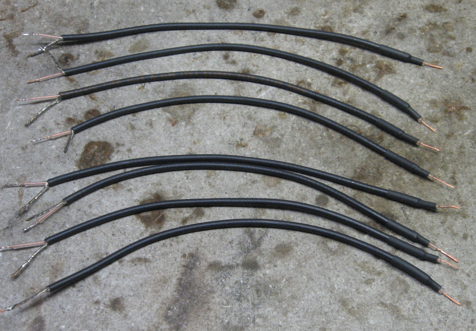
For the eight outputs and the audio input, we'll use coax. We're going to prepare nine 7in lengths such that the shield solders to the jacks only. Here's how:
|
||
|
Mounting Bracket Modification |
||
|
We had a 4 pot stooge bracket we'd gotten from Dave Wellington a couple years back. Bridechamber also has them. We drilled four 1/8" holes to match the screw holes in the PCB. |
||
|
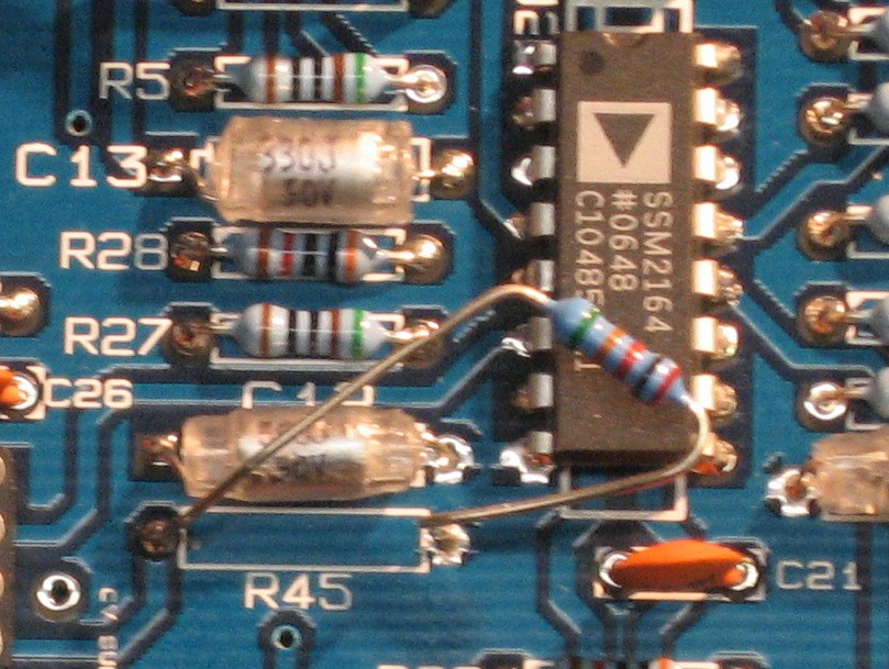
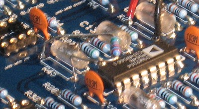
R45 - Tempco Resistor |
We decided to solder the tempco resistor (R45) in such a way that it would ust the SSM2164 IC as a heat sink. But we're not going to put the silicone grease on there until later in the building process.
|
|
|
PCB / Panel Connections |
1. Output and Input Coax and Jacks We soldered the coax into the PCB and then onto their jacks.
2. Input Pot Next we wired-up the 100K input potentiometer.
3. Fine / Course Controls
4. Control Voltage Jacks
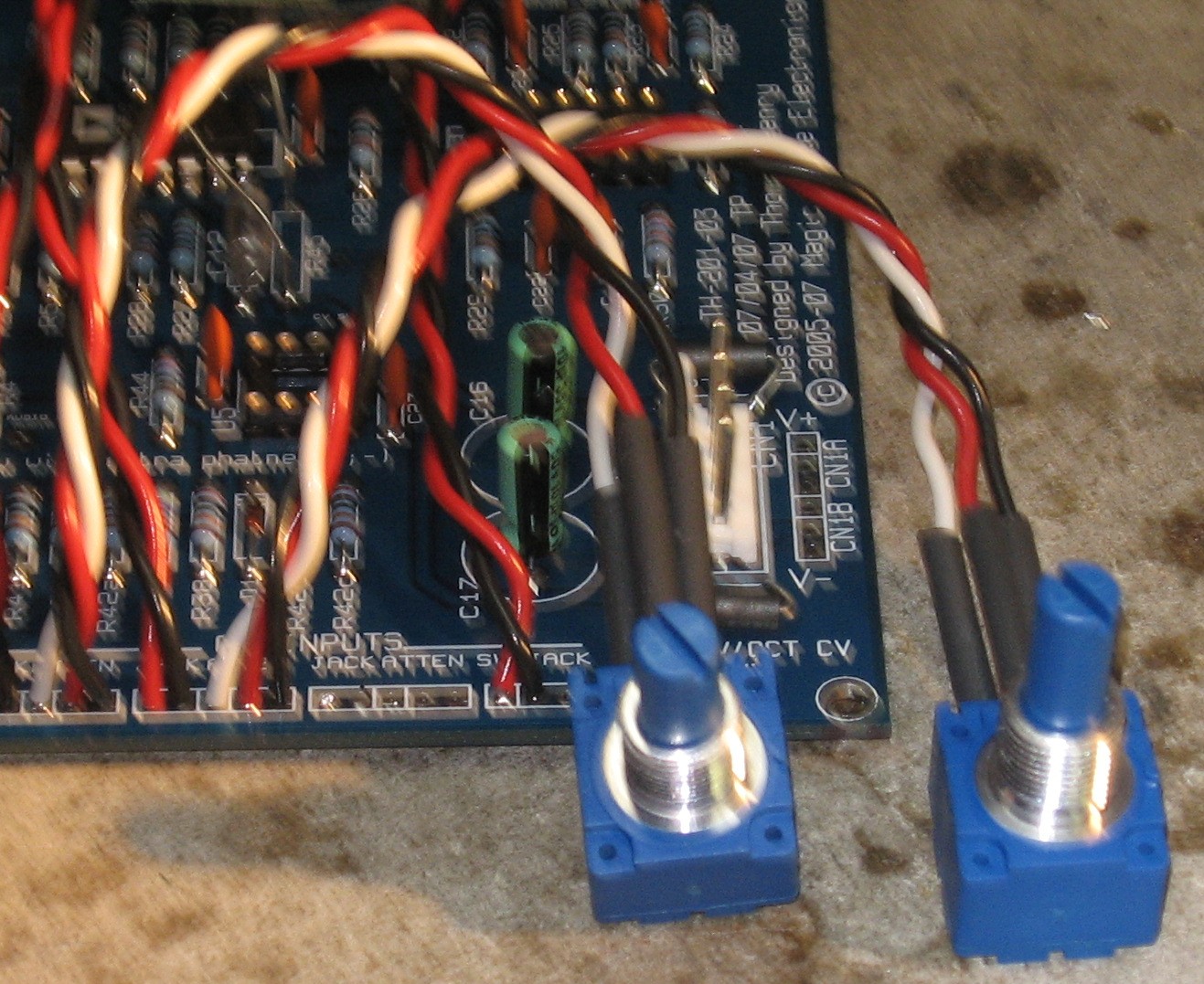
5. Control Voltage Pots
6. Connections Made - PCB
|
|
|
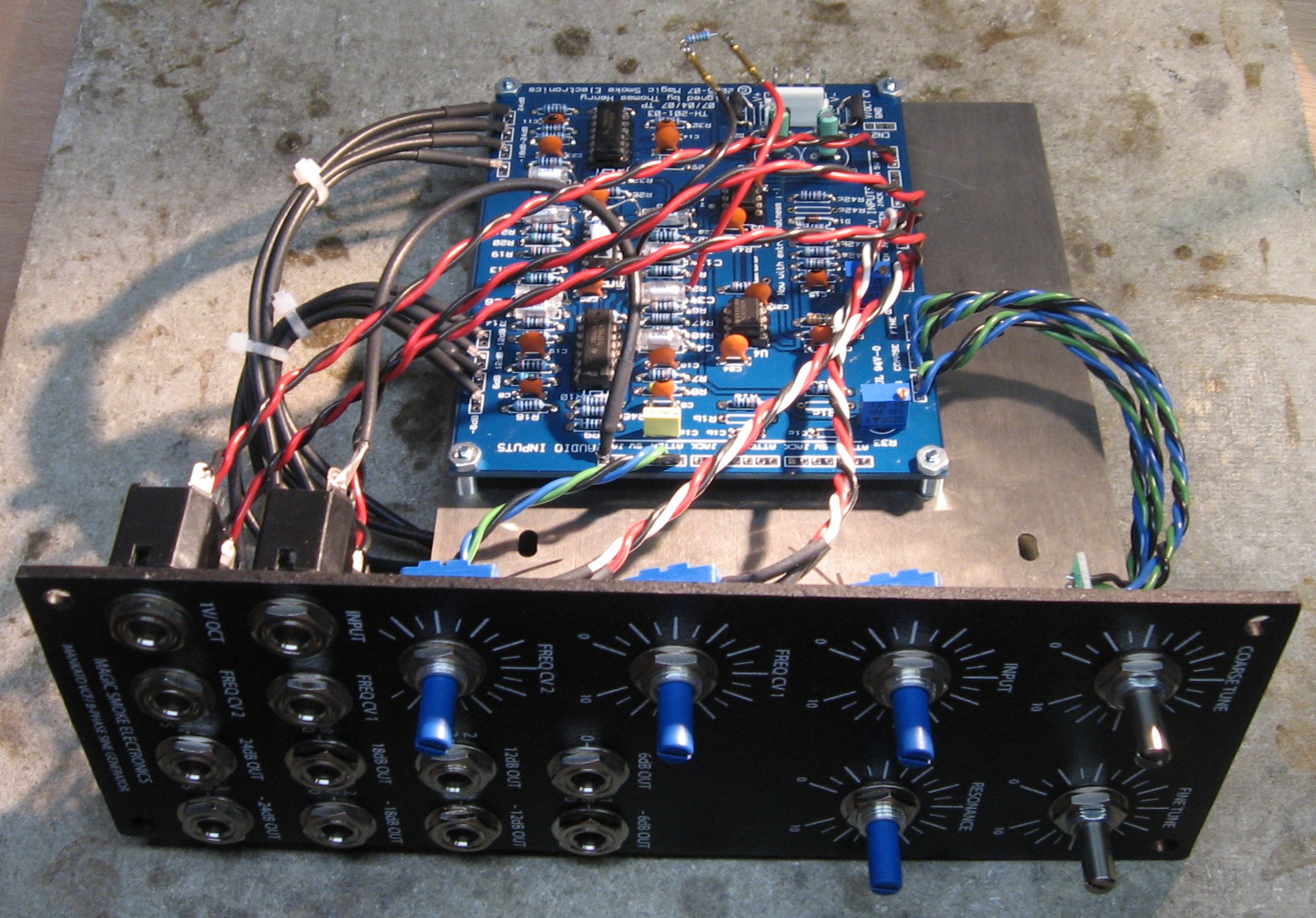
The PCB Mounted and Connected |
||
|
After mounting the PCB to the bracket, we started by attaching the output pots to the panel. Then we attached the bracket to the panel and finished the other parts.
|
||
|
Construction Done |
|
|
Set up / Testing |
||
Use Notes |
||
|
|


|
The fine Print: Use this site at your own risk. We are self-proclaimed idiots and any use of this site and any materials presented herein should be taken with a grain of Kosher salt. If the info is useful - more's the better. Bill and Will © 2005-2011 all frilling rights reserved
|