Bill and Will's Synth
|
|
Table of Contents |
|
This page has become really long, so here's a table of contents that we hope will make it easier to traverse: Background - presents an explanation and Paul Schrieber's initial description of the Module. Parts - presents a Bill of Materials and notes about it Panel - presents the MOTM format panel Construction Phase 1 - Resistors, Capacitors, IC Sockets, Power Plugs, MTA headers Construction Phase 2 - Trimmers, Panel connections |
Background |
|
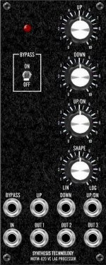
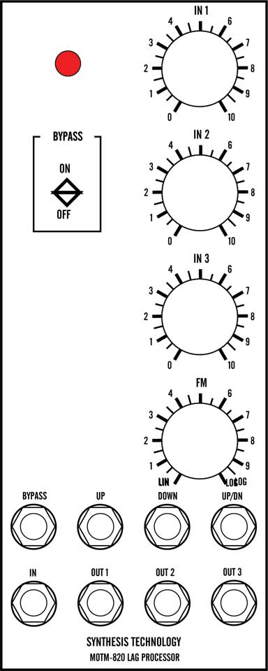
Paul Writes: The MOTM-820 is used to add slew to an input. The most common use would be to add portamento to a control voltage feeding a VCO (hopefully, a MOTM-300 VCO). In analog keyboards with portamento (Moog called this glide) the rise and fall times were the same. This is because a simple RC filter is controlled by a single pot. The shape is the same: an exponential rise and fall. Although we are used to hearing this shape, the fact that we have an exponential voltage feeding an exponential response (1V/Oct of the VCO) means that musically we are limited. The MOTM-820 is your solution! It is the most advanced lag processor ever designed. How can we claim this? Well, just check out the features:
The MOTM-820 also offers a "hidden multiple": it can drive 3 VCOs (or other modules) from a single input! The output stage is a special "capacitive cable driver" for driving long cables (up to 20 feet) without any voltage drop!
|
Parts |
|
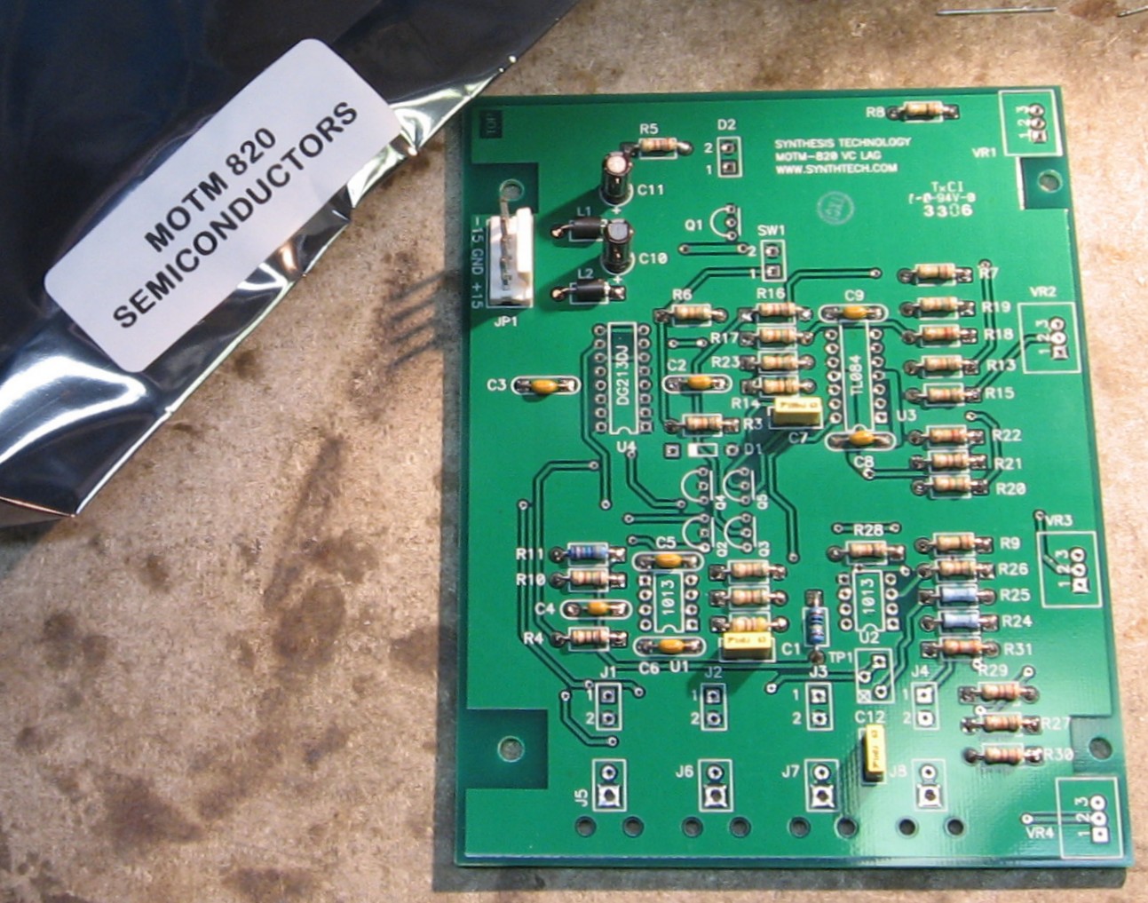
In 2008 (or about that time), Synthesis Technology stopped producing full-blown kits, and moved toward what Paul calls "2.0" (two-dot-oh) DIY. This assumes the builder will buy certain parts from Synthesis Technology - PCB, Panel, and in some cases a Special Parts Kit of the particularly hard to find parts - and will get the rest of the parts from Mouser or Digikey or - well - wherever. For those who are building this as a "two-dot-oh" project, Will and I, with feedback and review from others, have developed a parts-list / bill-of-materials in the form of an XL spreadsheet (as usual). Please don't take it as gospel. We've been over and over it and are relatively confident in our specifications - and we hear that several people have used it successfully so you should be good. The BOM assumes that you get the "extra parts kit" from Synthesis Tech. Synthesis Technology offers some parts like pots and knobs at particularly good prices... these options are offered in the BOM.
Click here to download our XL spreadsheet Parts List |
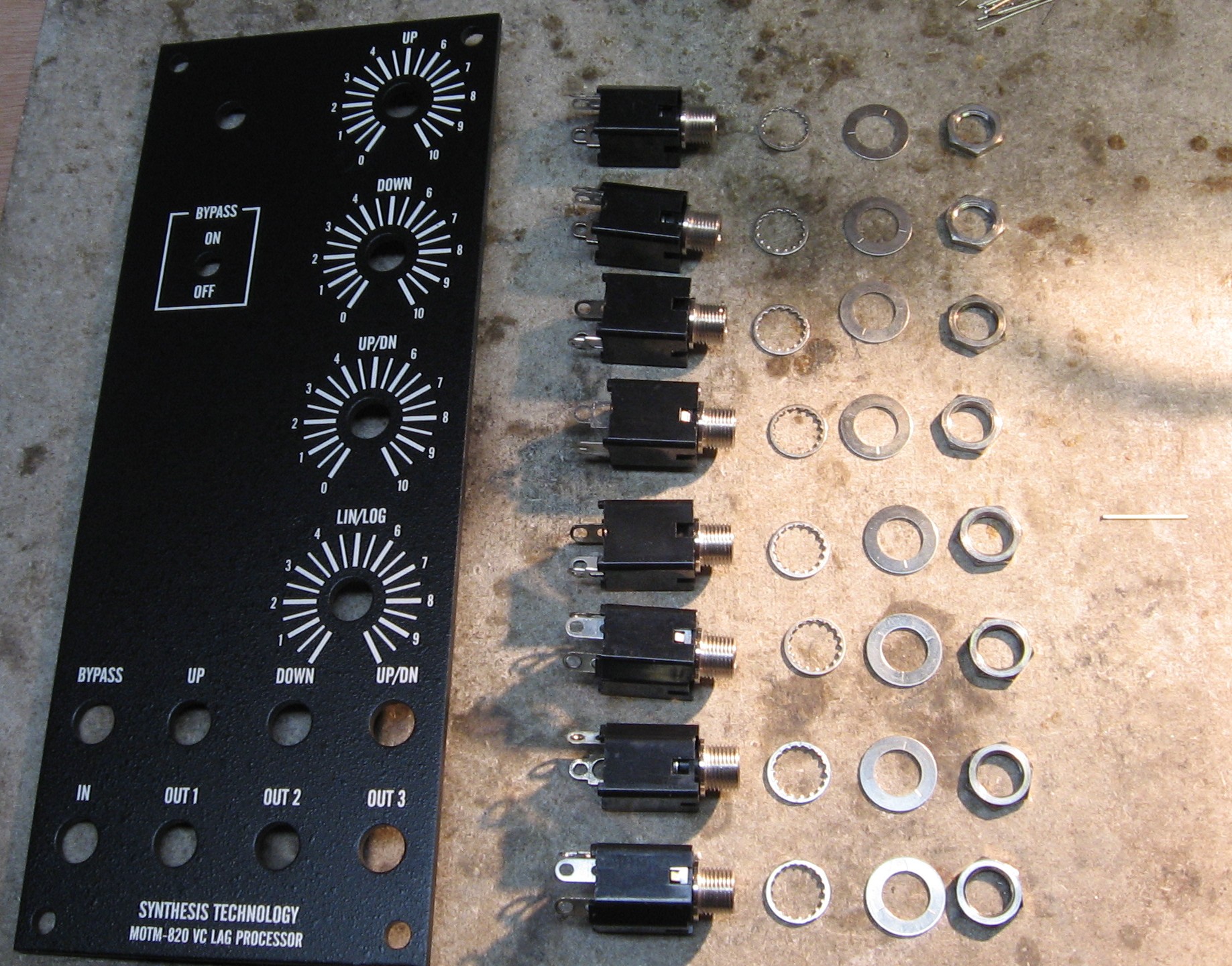
Panel |
|
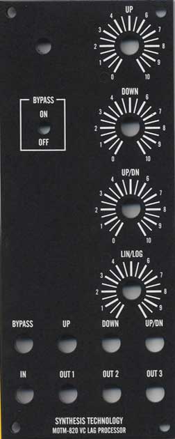
If you're building this as a "two-dot-oh" project, we also assume you get the panel from Synthesis Technology:
|
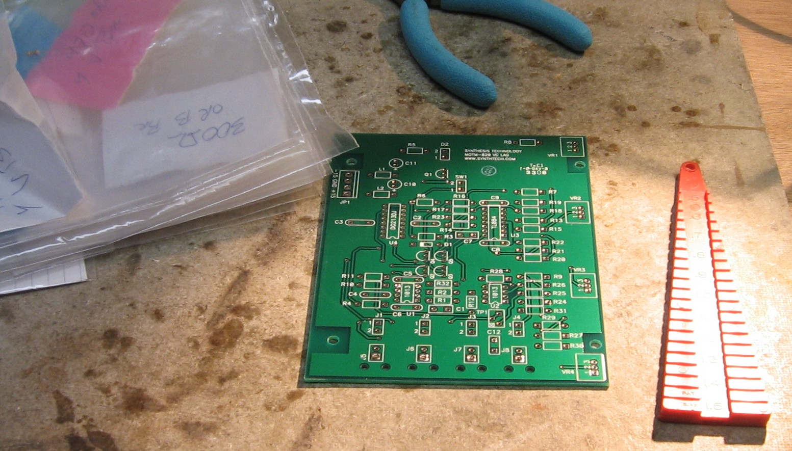
Construction Phase 1
All the stuff in Phase 1 gets soldered using "Organic" Solder. At every break in the action, we wash the board off to get rid of the flux. |
|
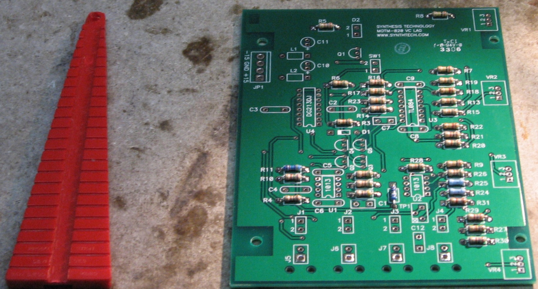
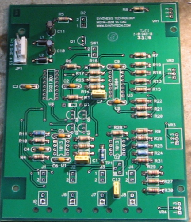
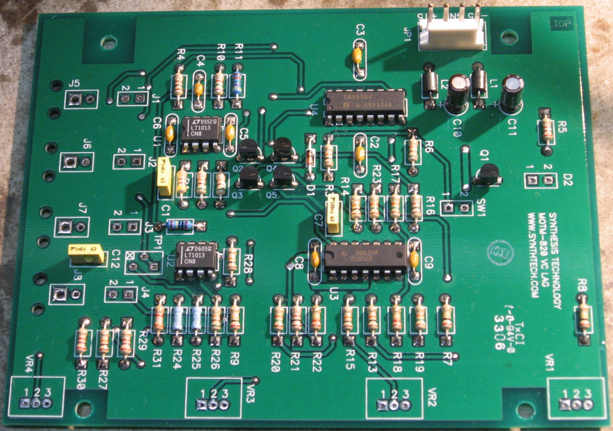
Resistors |
|
|
|
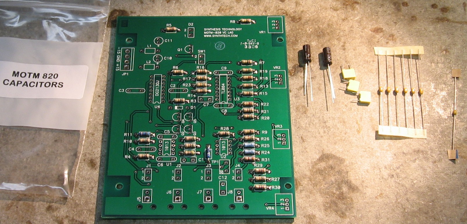
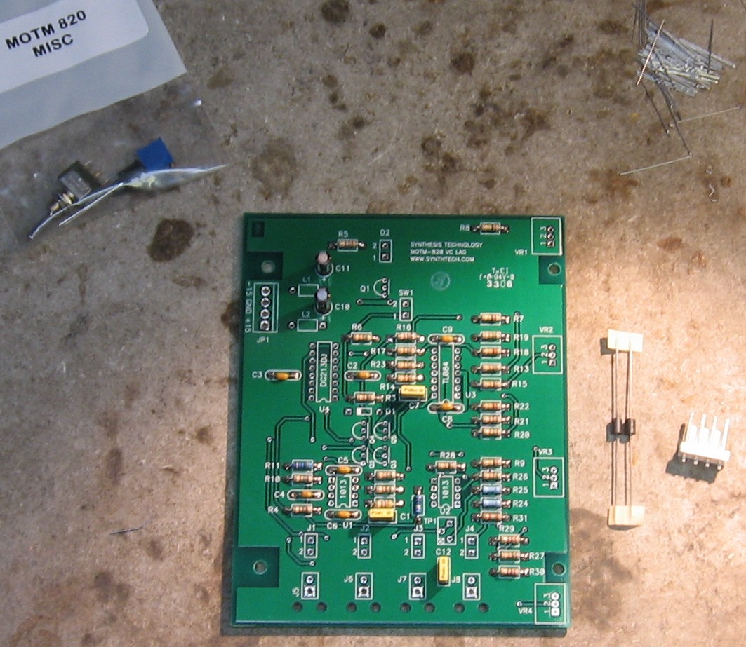
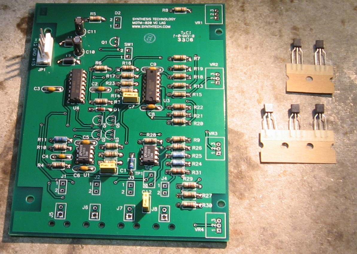
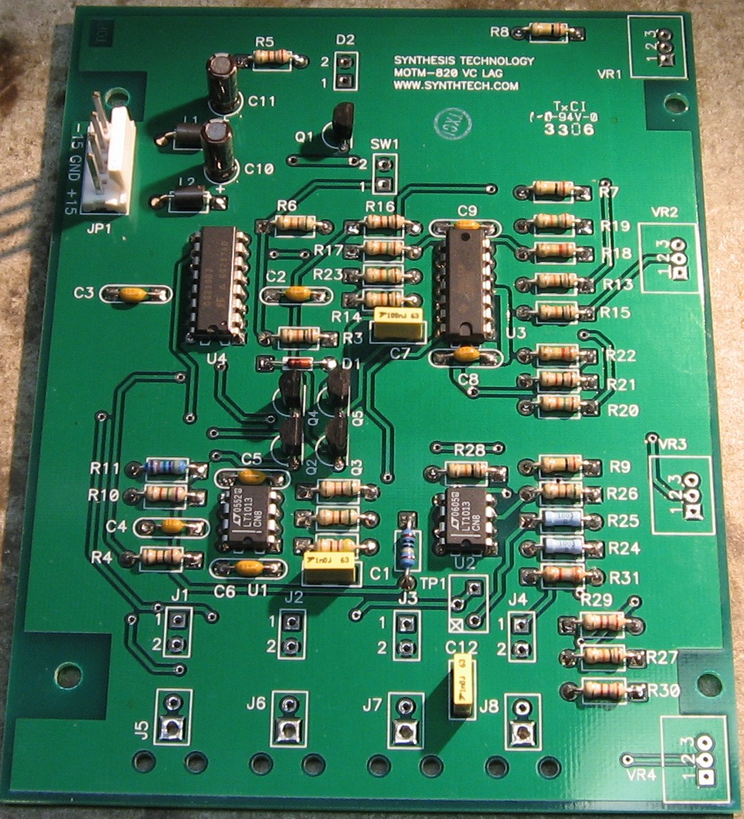
Capacitors - Misc - Semiconductors |
|
|
|
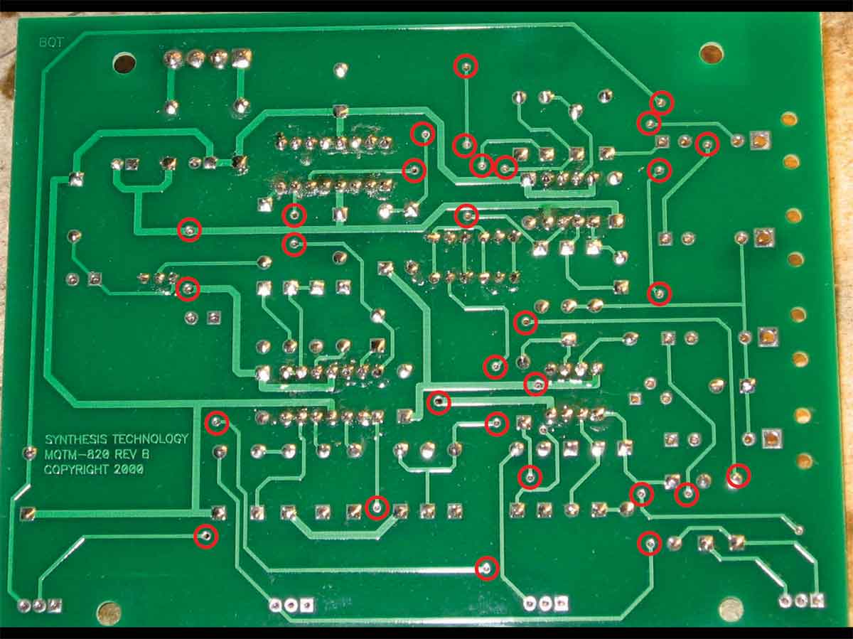
Via Holes |
|
|
Construction Phase 2All the stuff in Phase 2 gets soldered using "No Clean" Solder. |
|
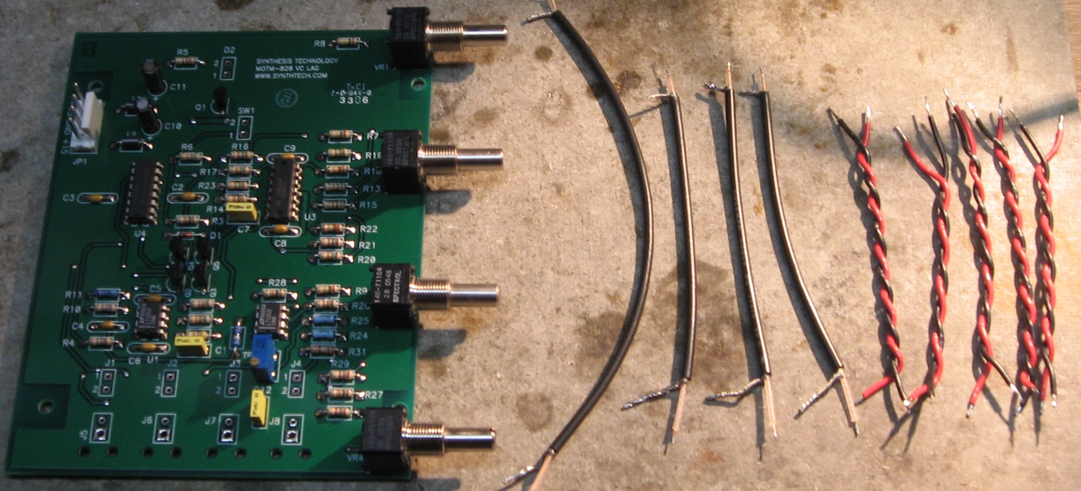
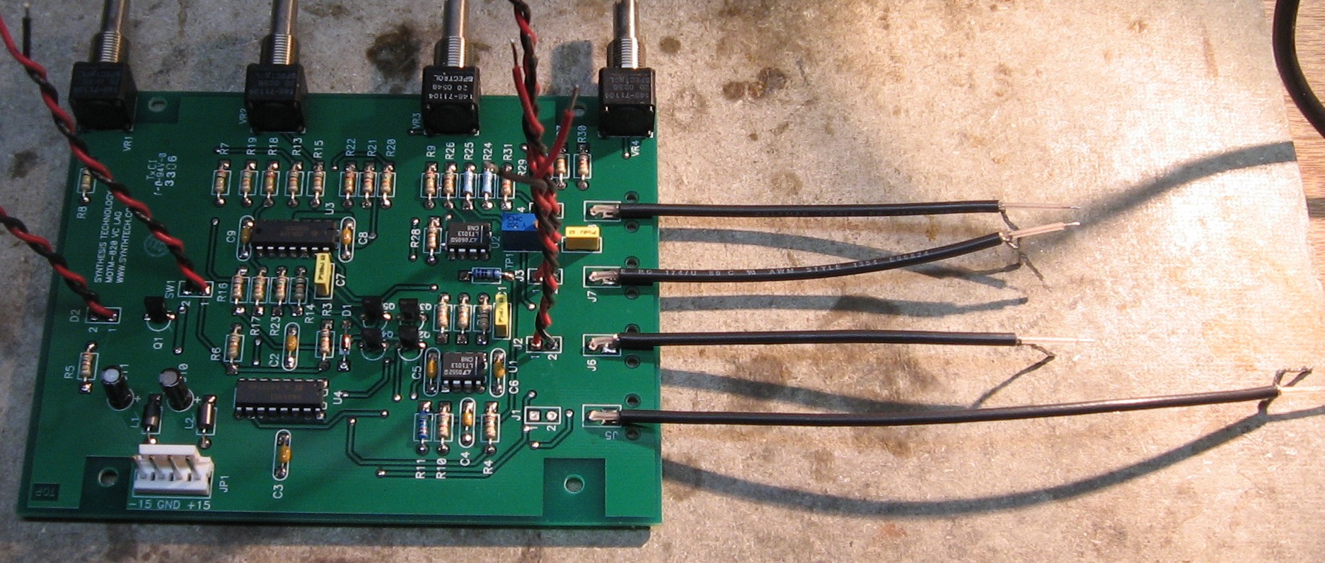
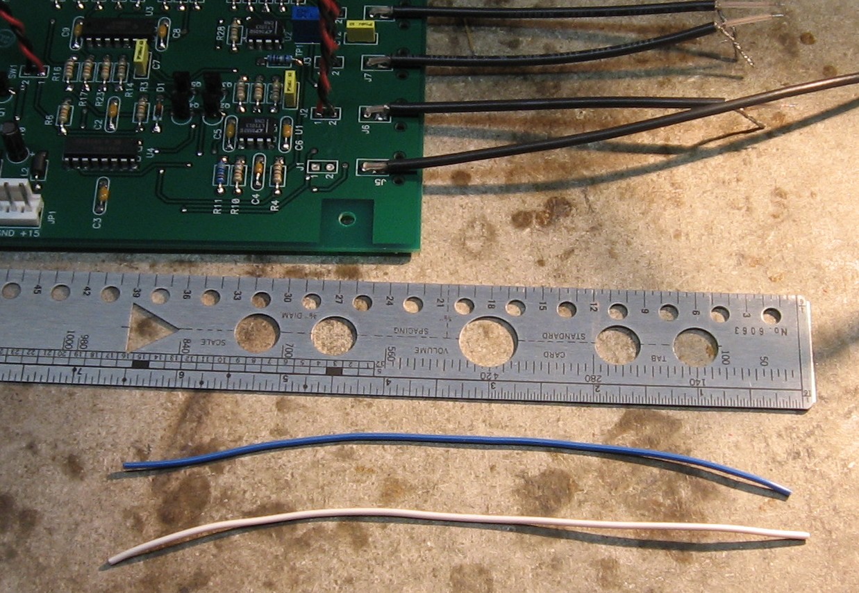
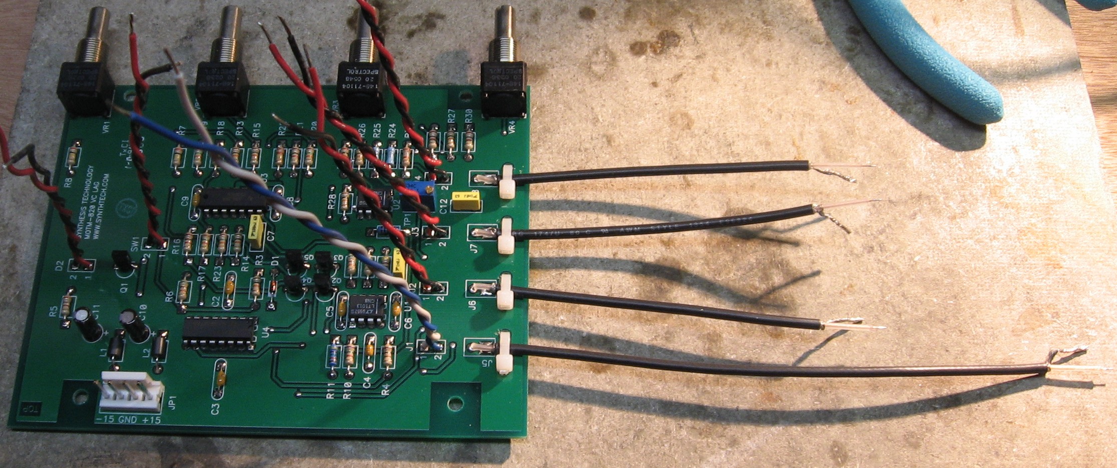
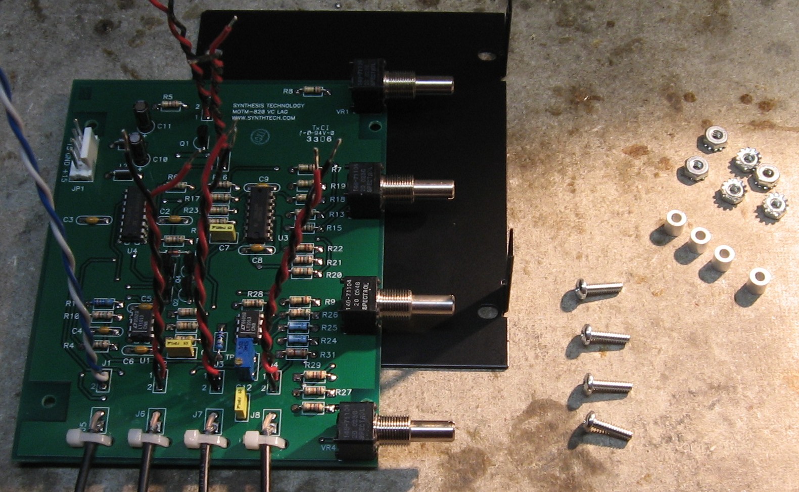
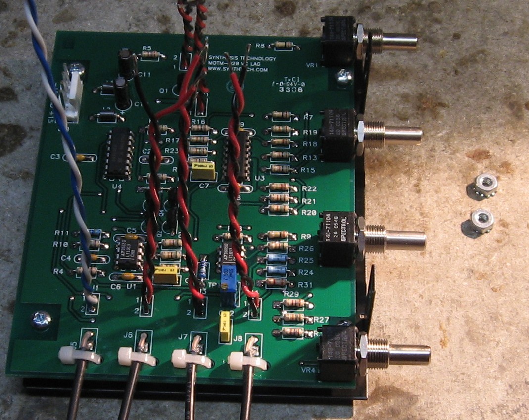
Pots, Temco, Wires |
|
|
|
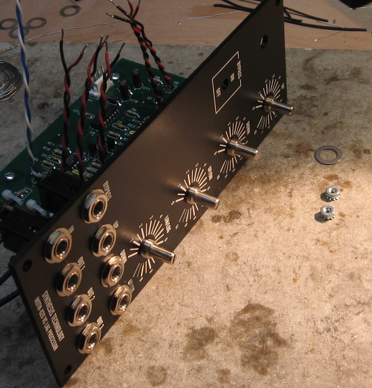
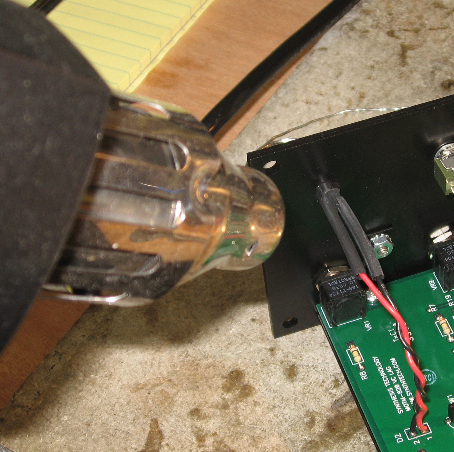
Prepare the panel |
|
|
|
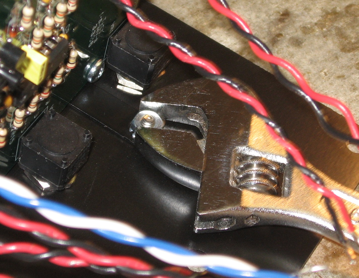
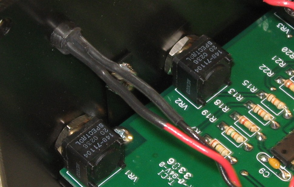
Bracket |
|
|
|
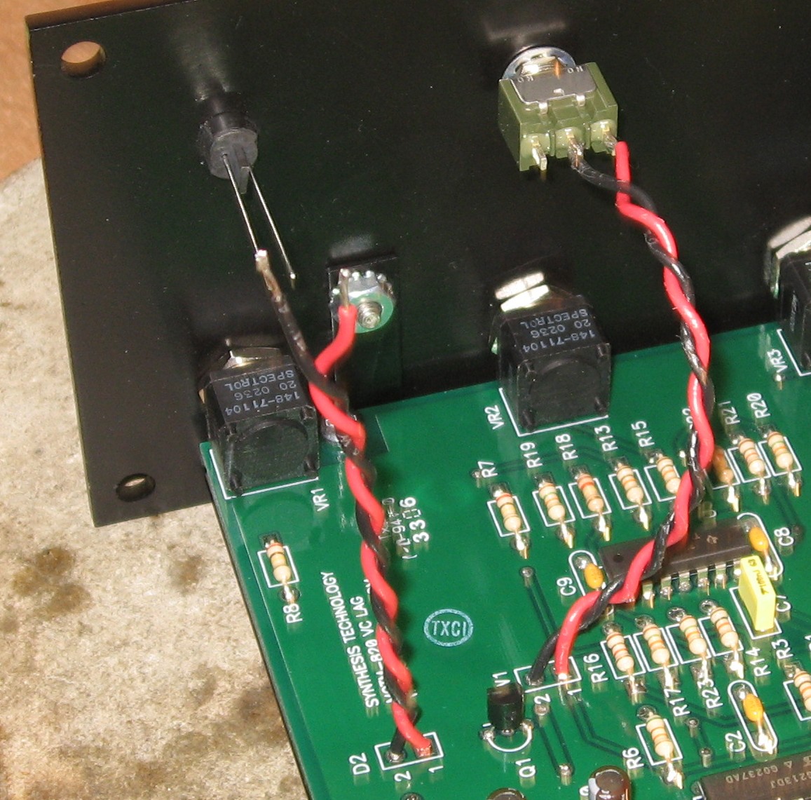
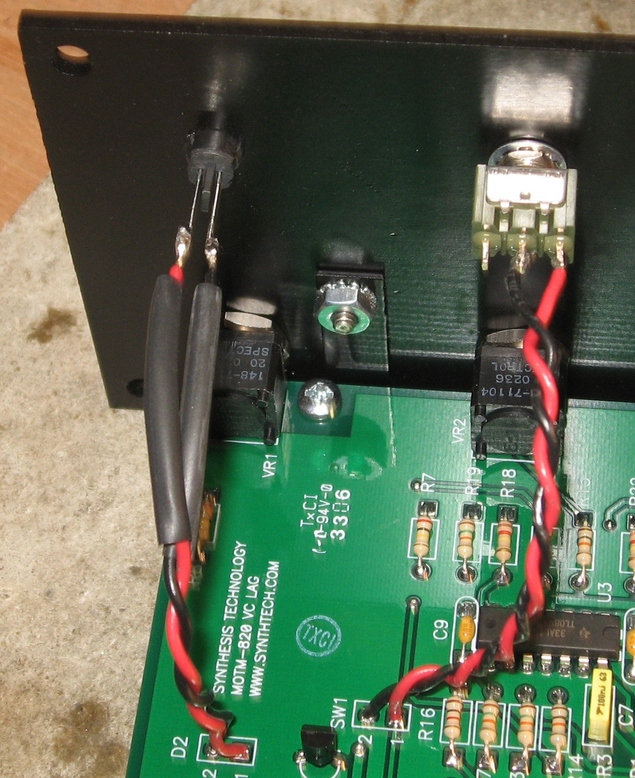
Wiring the switch and LED |
|
|
|
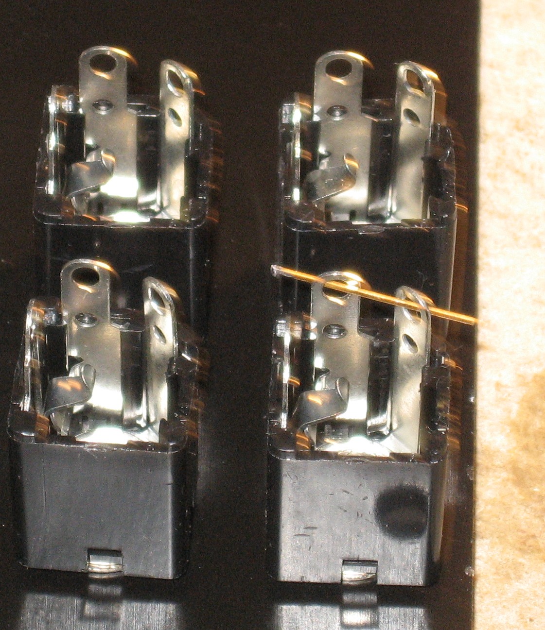
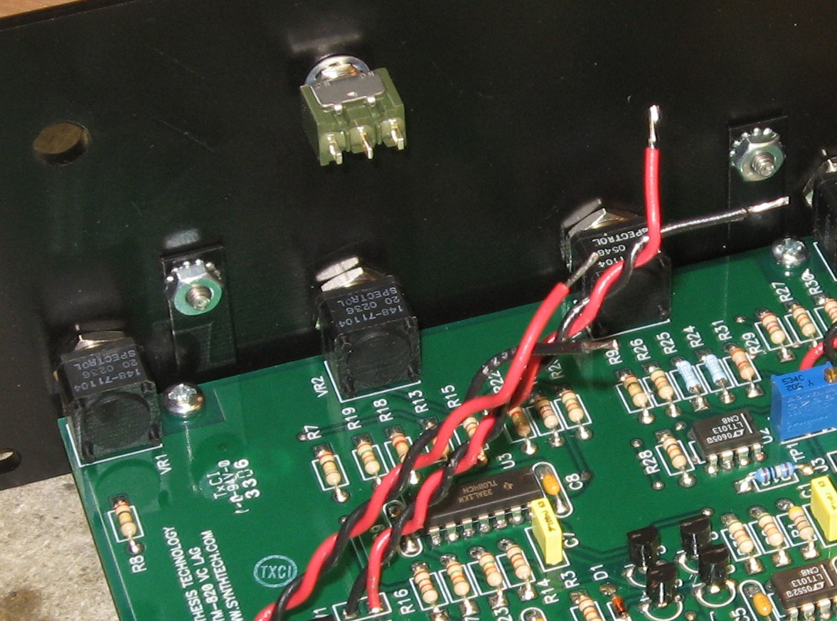
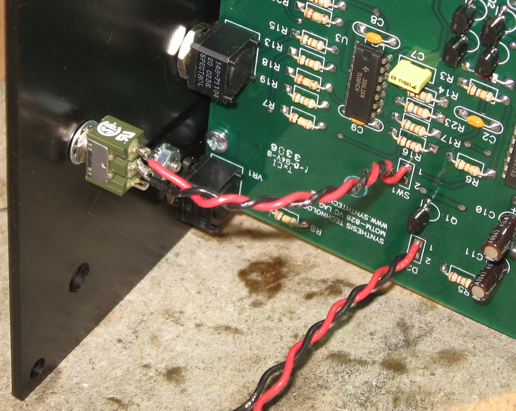
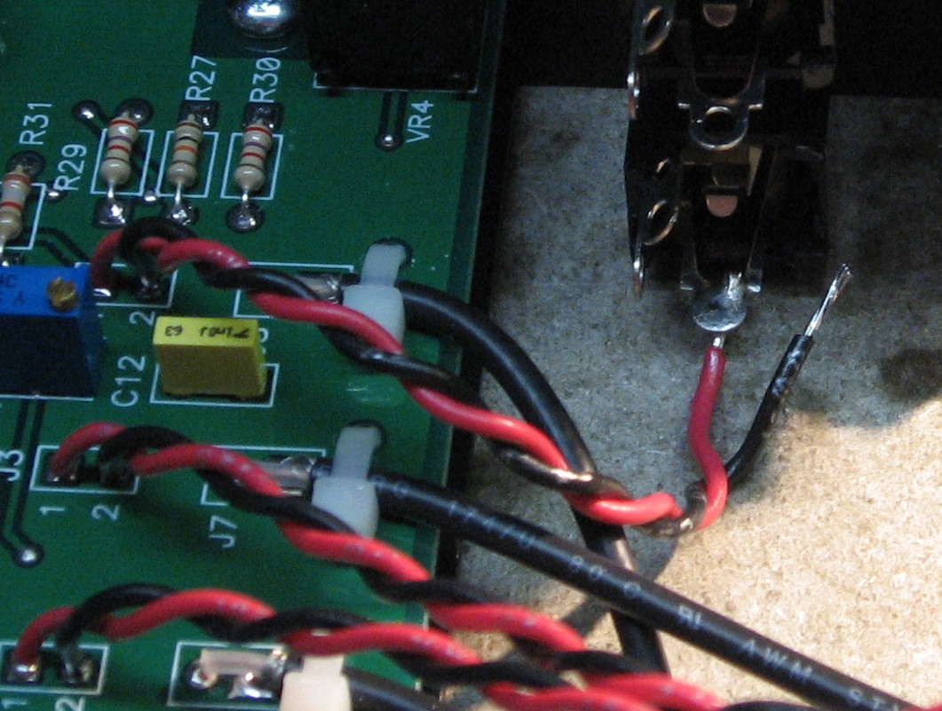
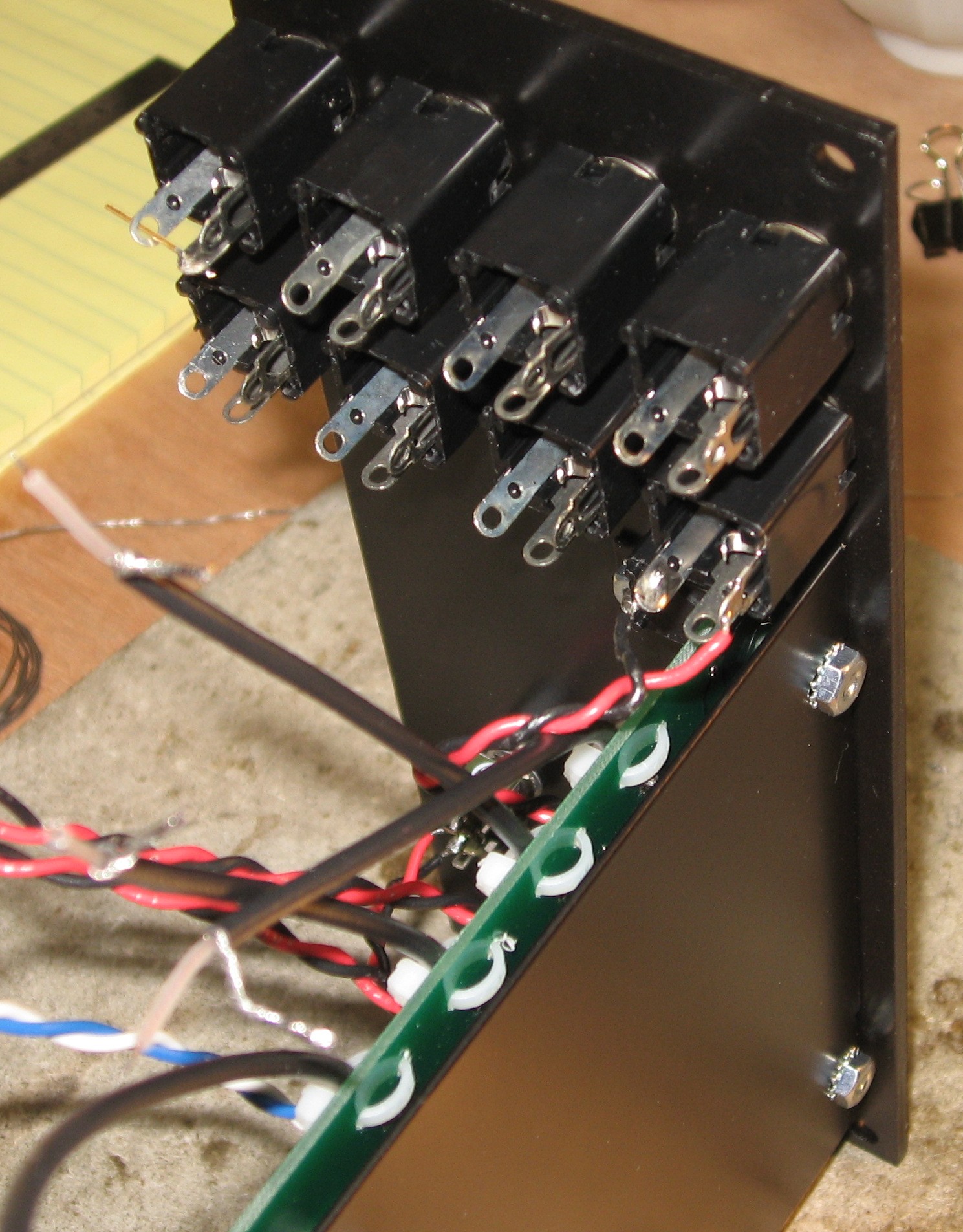
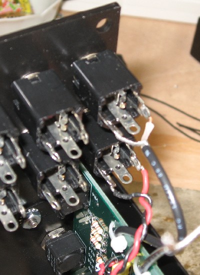
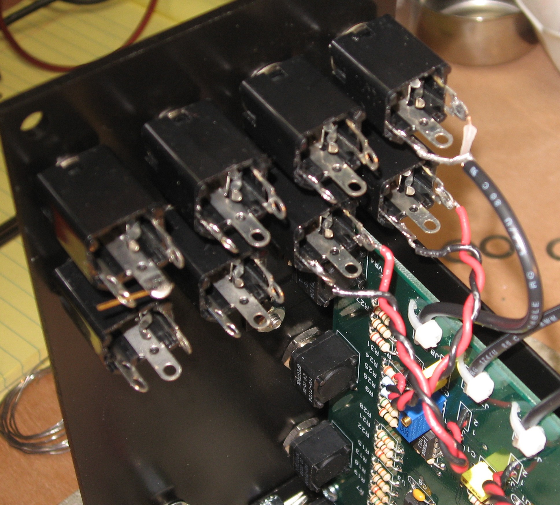
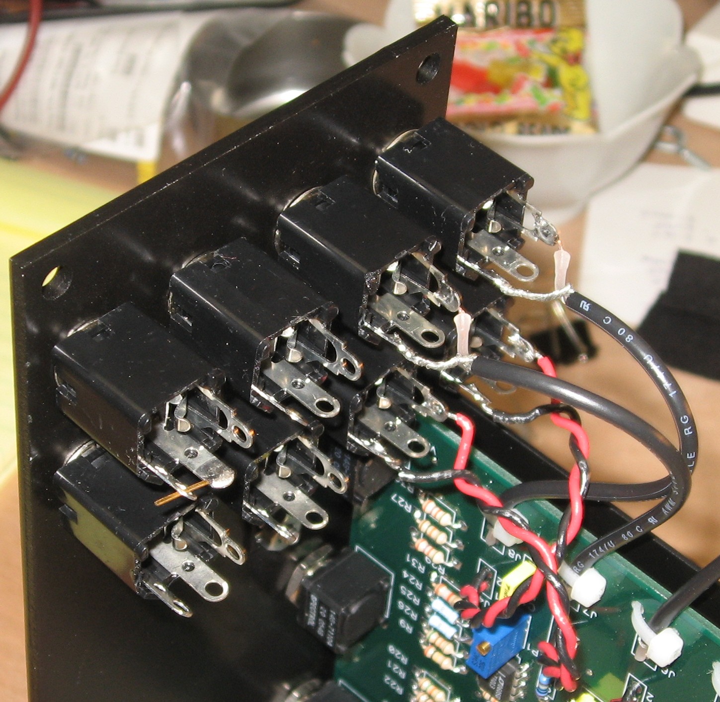
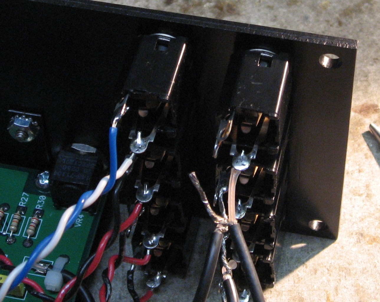
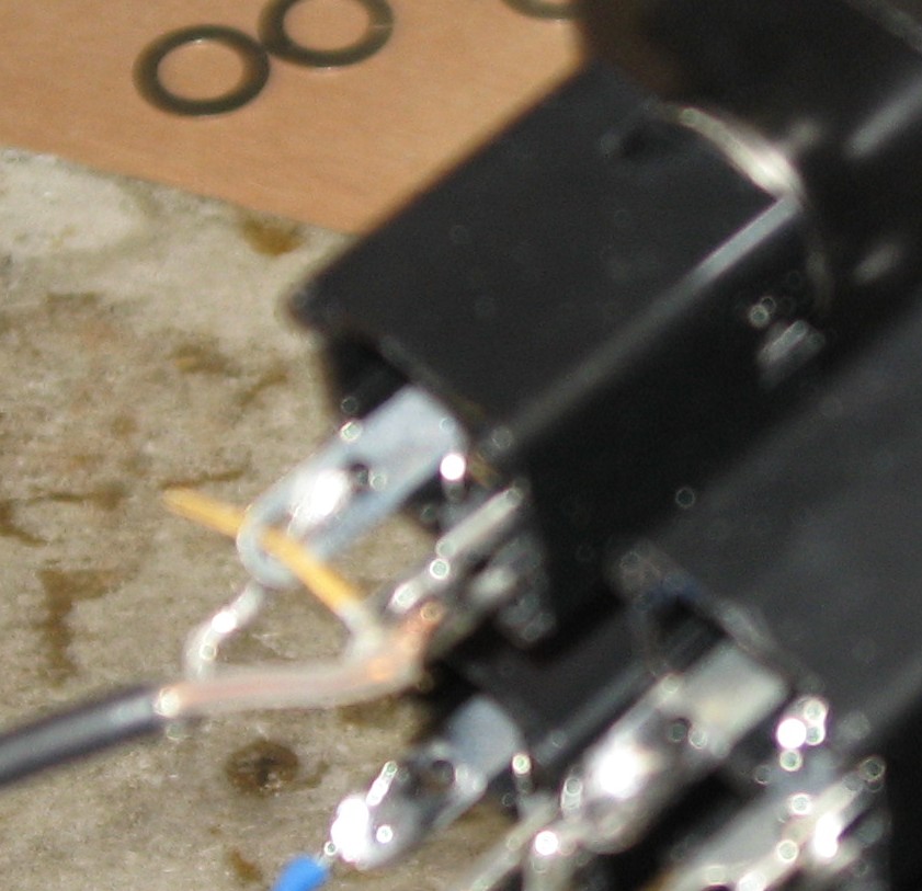
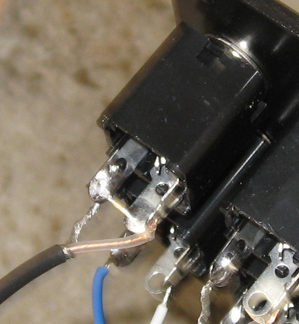
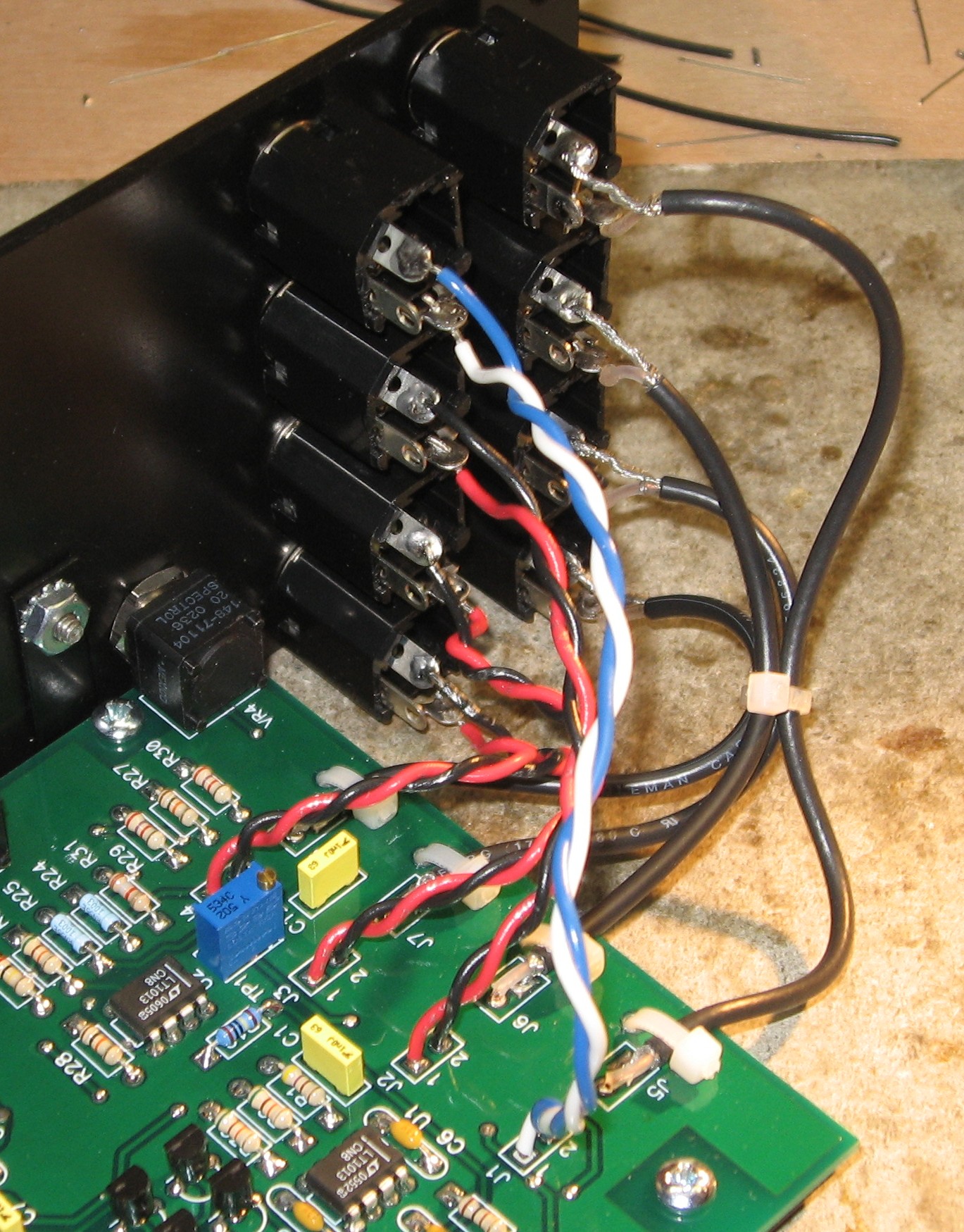
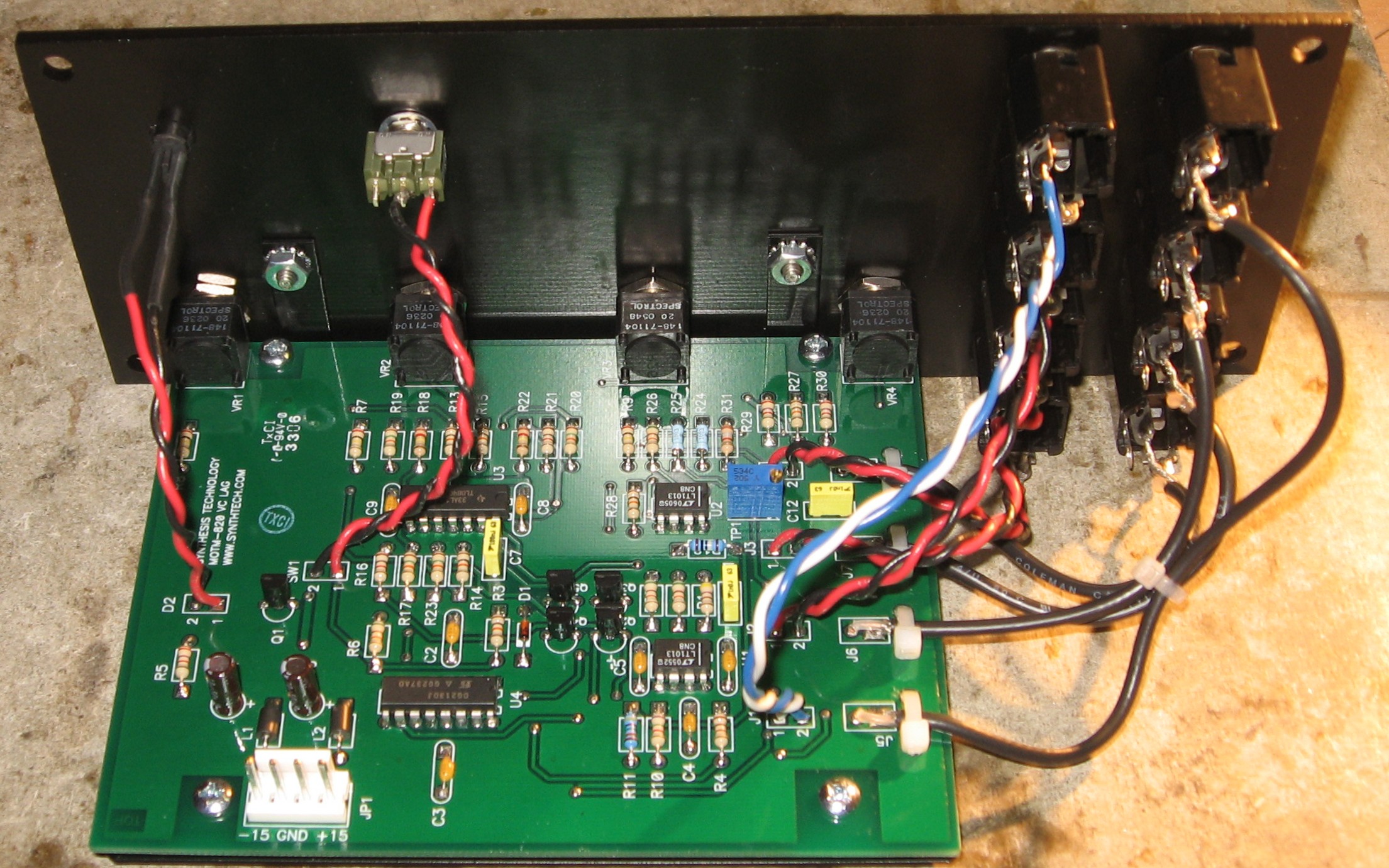
Wiring the jacks |
|
|
|
Knobs, Ties |
|
|
|
Construction Done |
|
|
Set up / Testing |
Use Notes |
|
|


|
The fine Print: Use this site at your own risk. We are self-proclaimed idiots and any use of this site and any materials presented herein should be taken with a grain of Kosher salt. If the info is useful - more's the better. Bill and Will © 2005-2011 all frilling rights reserved
|