Bill and Will's Synth
|
||
Table of Contents |
||
|
Here's a table of contents that we hope will make it easier to traverse this page: Background - presents an explanation and Paul Schrieber's initial description of the Module with a photo Parts - presents a Bill of Materials for "two-dot-oh" builders and notes about it Panel - presents the MOTM format panel Construction Phase 1 - Resistors, Capacitors, IC Sockets, Power Plugs, MTA headers Construction Phase 2 - Trimmers, Panel connections |
||
Background |
||
|
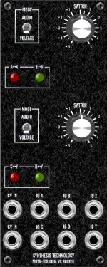
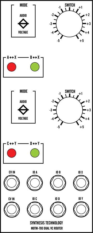
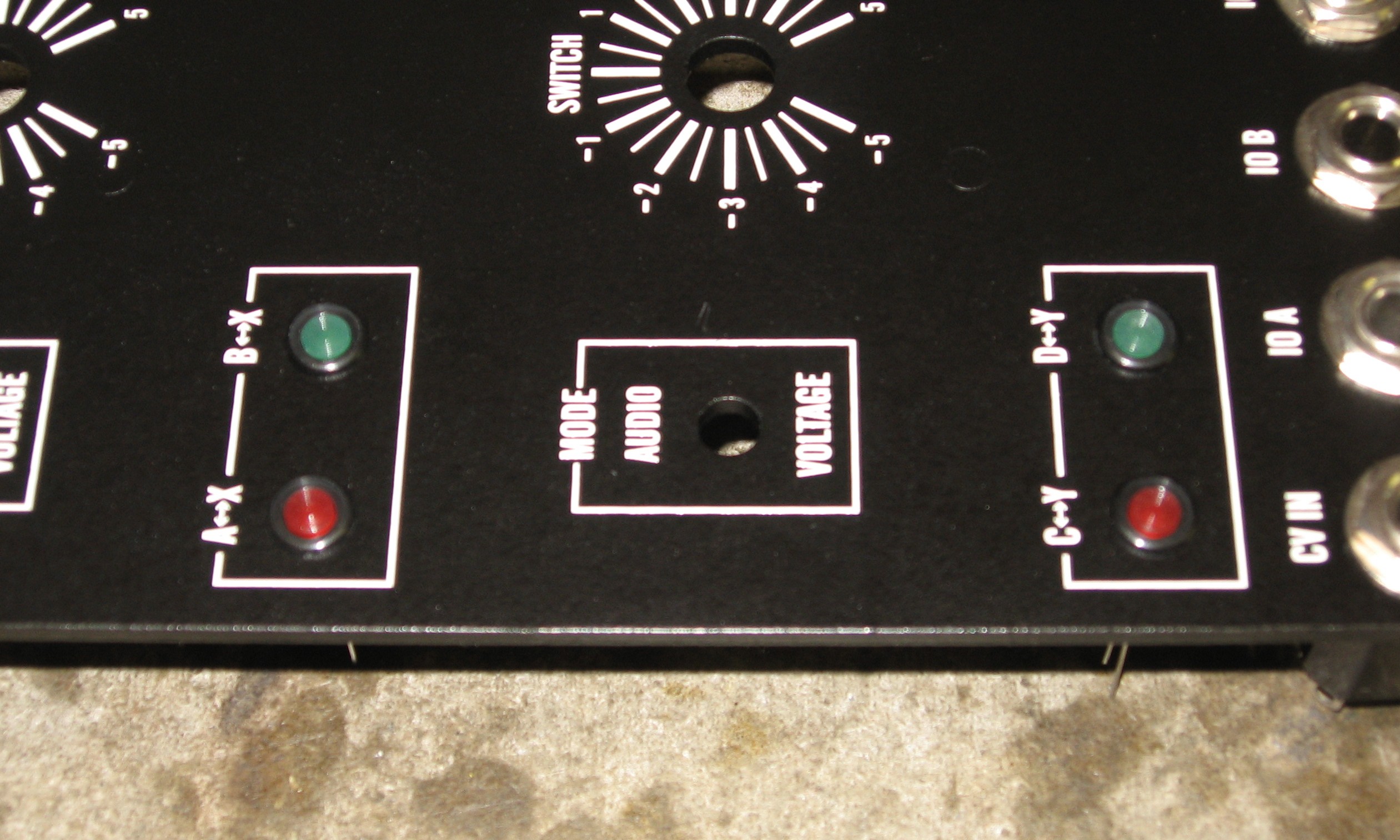
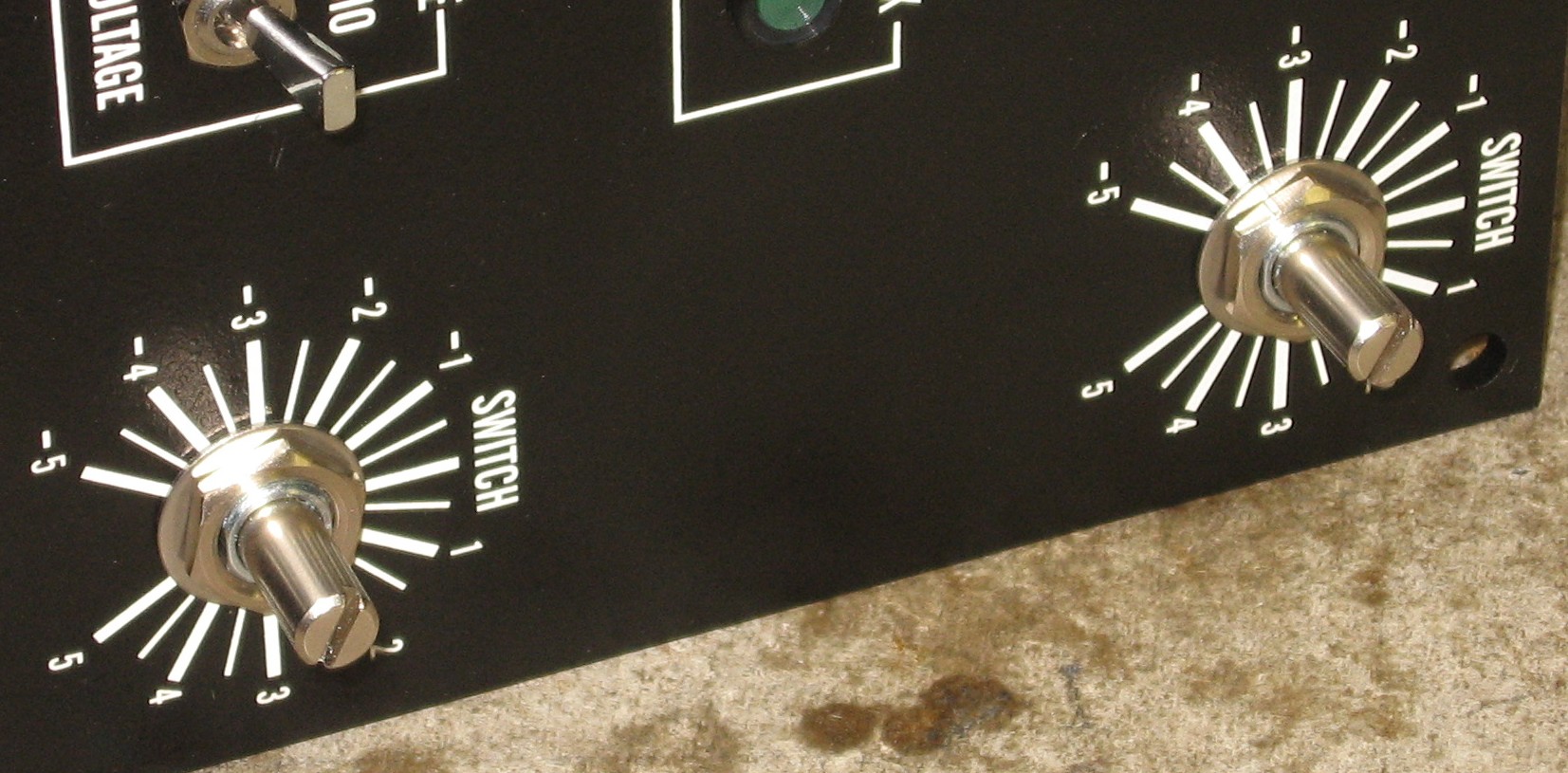
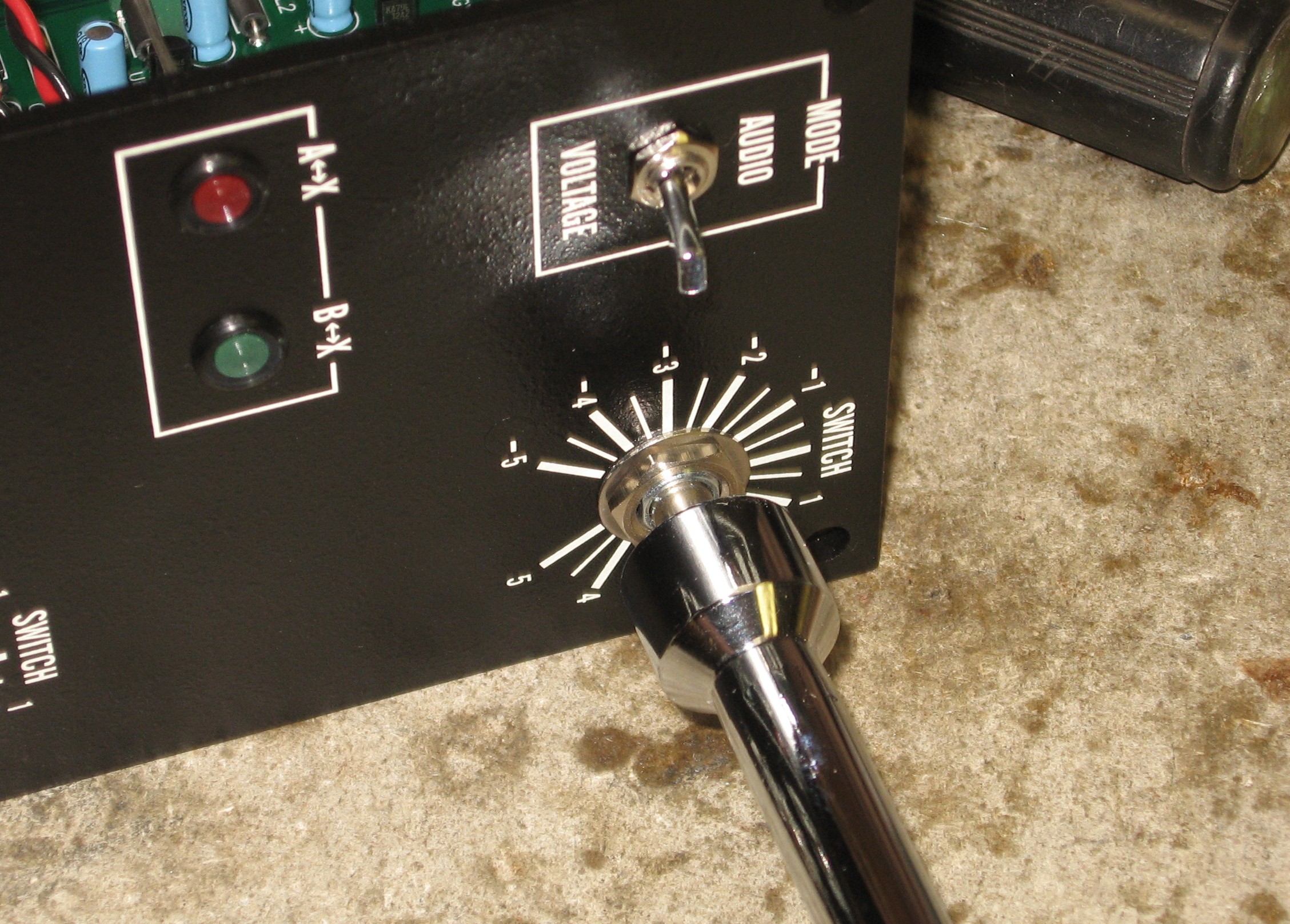
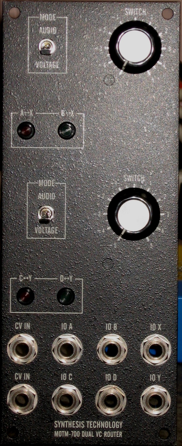
Paul Writes: "The MOTM-700 is another Synthesis Technology exclusive module! It is a bi-directional, dual SPDT switch that is "toggled" when an input control voltage exceeds a trip-point set by a panel knob. Special circuitry handles routing of audio (cross-fading VCAs) or control voltage (fast, low-offset switches). "The MOTM-700 has 2 identical sections, so we will discuss how one of them operates. The two are totally independent from each other, and by patchcords can be connected in series or parallel with each other, or to additional MOTM-700 modules. "Think of a SPDT (single-pole, double-throw) mechanical switch. When the switch is 'up', Signal A is connected to the "Common" terminal (let's call it 'X'). So we say, "A is routed to X". If the switch is 'down', then Signal B is connected to X. There are 2 ways of veiwing the connections: 2 inputs are selected to 1 output, OR 1 input is routed to 2 outputs. The switch doesn't care: it's truly bi-directional. "This is exactly how the MOTM-700 works! What makes it useful in any studio is that you control the selection with a control voltage! The MOTM-700 uses a circuit called a comparator that "compares" the input control voltage with another voltage, set by the panel pot SWITCH. The SWITCH control is adjustable from -5V to +5V. "Operation is easy to remember:
"So, what is it good for? The fun part is choosing the source of the CV input. Here are just a few examples:
"A MODE switch selects if audio or control voltages are being routed. In the AUDIO position, a special IC actually switches by a very fast cross-fading between channels. This eliminates "pops" and "clicks". The IC is rated for CD quality switching: better than 90dB SNR with less than 0.002% THD. Shielded RG-174 cables are used for all audio signals. "If the MODE is voltage, then a high-speed, low resistance CMOS switch is used (NOT the cheesy '4066' types!) This IC is good enough for switching VCO control voltages without adding drift or offsets! It can also switch at audio rates as well! This can result in some very bizarre timbres. Check out the demo files! "We think that the MOTM-700, once understood, will find 100's of uses in your studio. Not just as another module in the MOTM family, but as a 'stand-alone' accessory for routing just about any signal in your setup." |
||
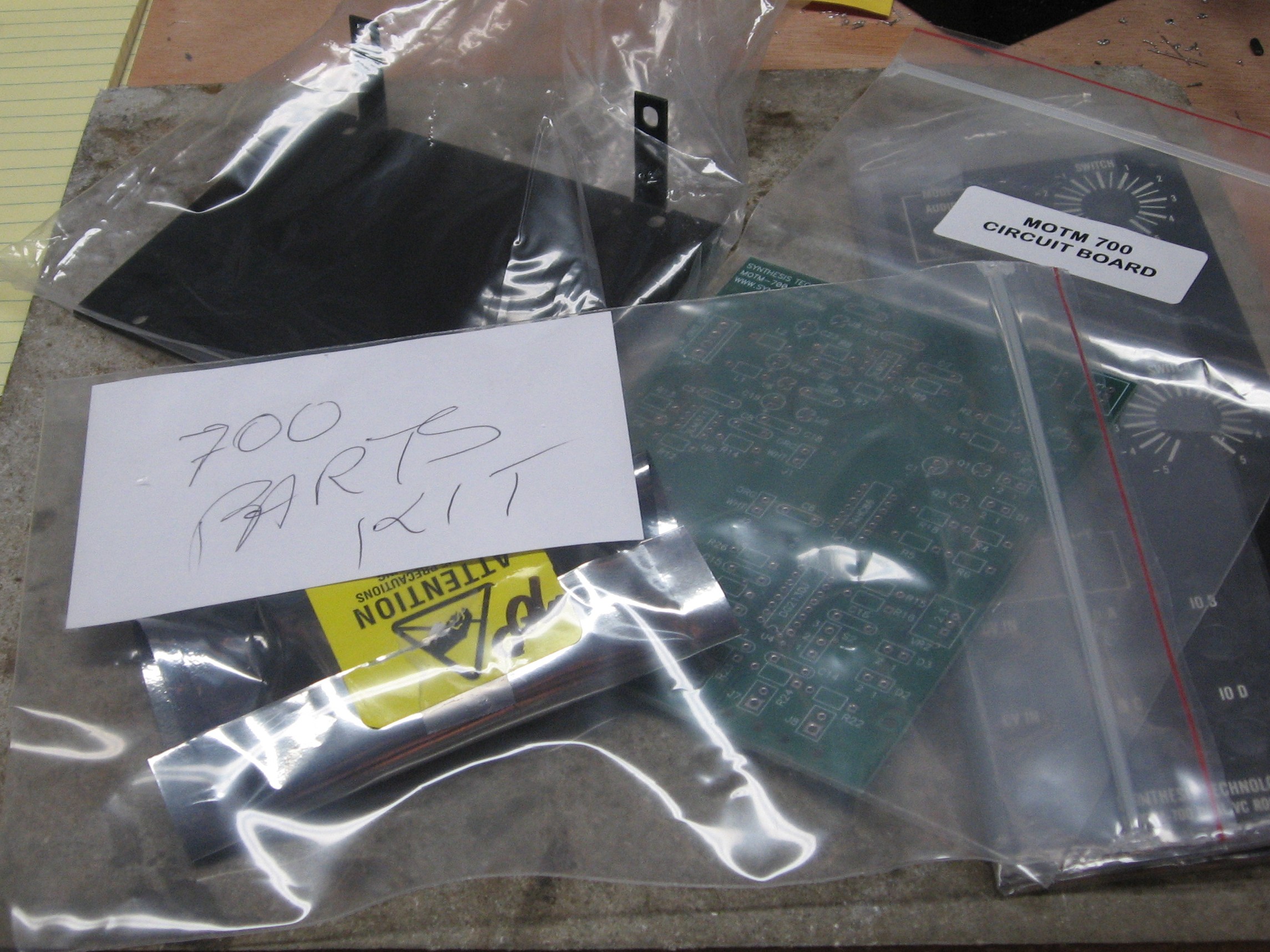
Parts |
||
|
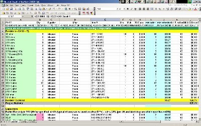
Will and I have developed a parts-list / bill-of-materials in the form of an XL spreadsheet. In the BOM, the left-most column is the "part." The parts we've ordered have a green background. These parts we have a high (but not perfect) level of confidence that we've specified correctly - we caught a mistake or two in part numbers / prices as we were ordering. please double-check us and let us know of mistakes you find. Corrections to BOM: None yet - Notes: None yet - Click here to download the spreadsheet (apx. 48K).
|
||
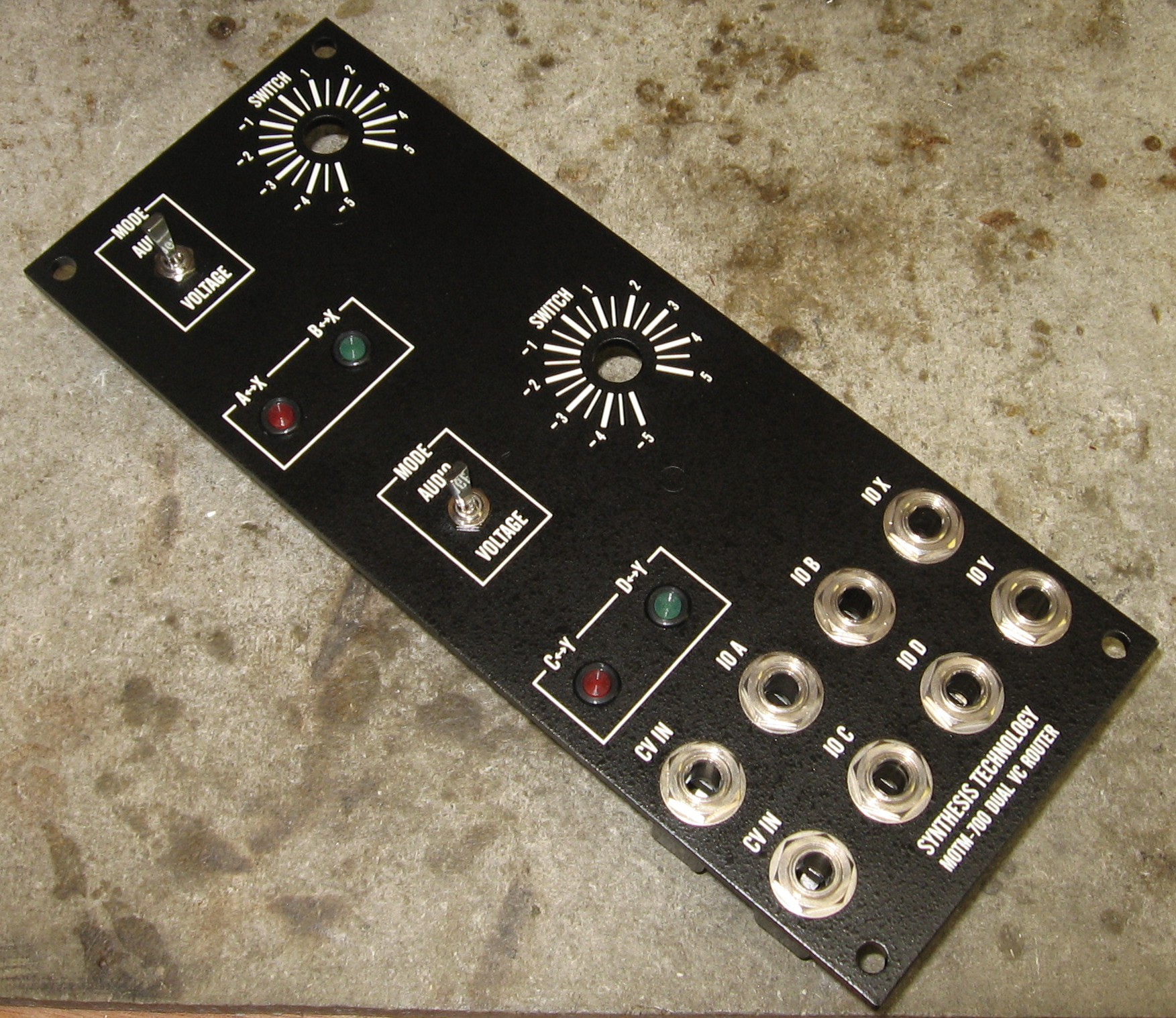
Panel |
||
|
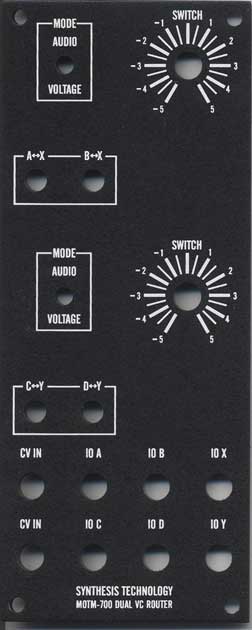
If you're building this as a "two-dot-oh" project, we also assume you get the panel from Synthesis Technology:
|
||
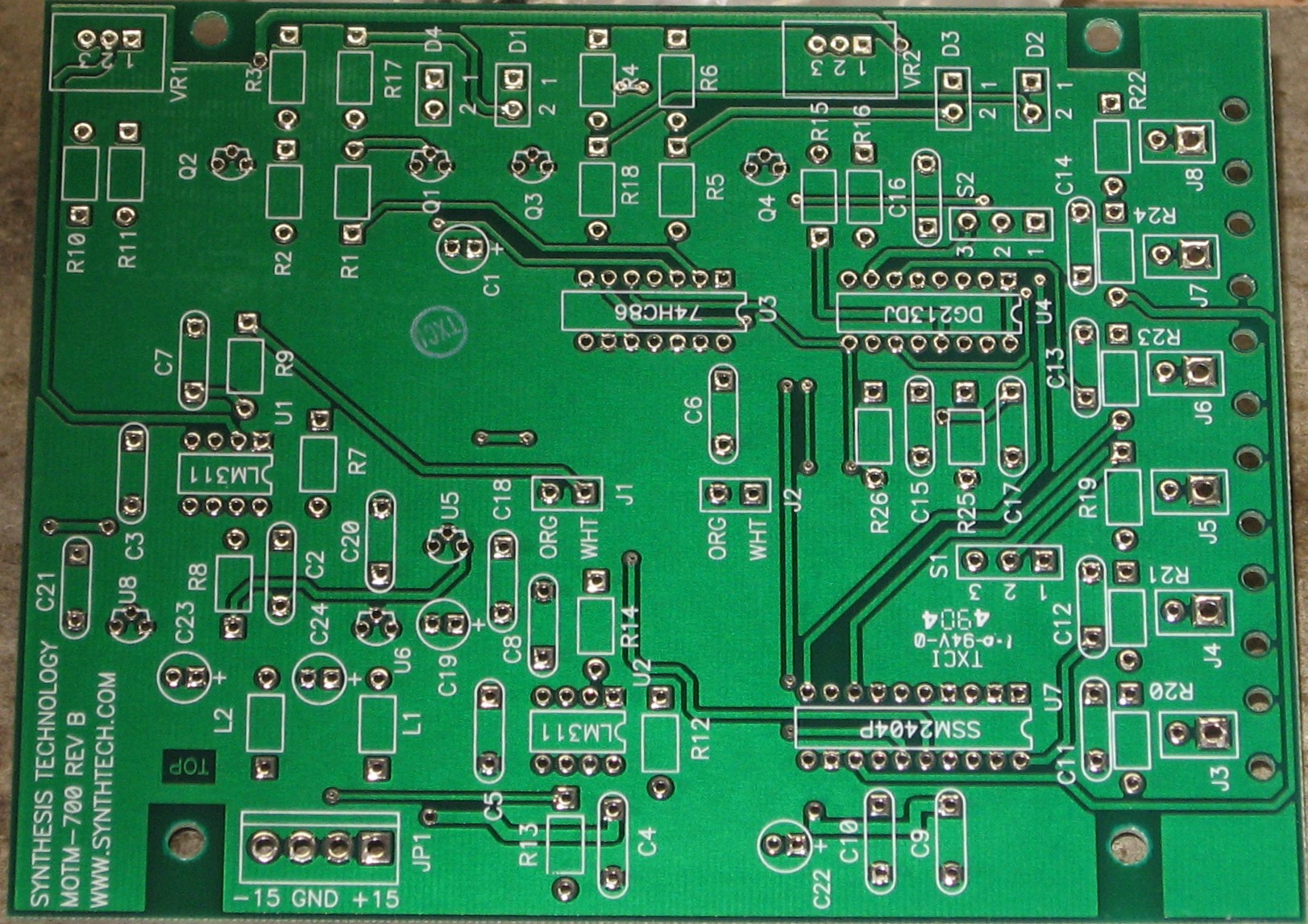
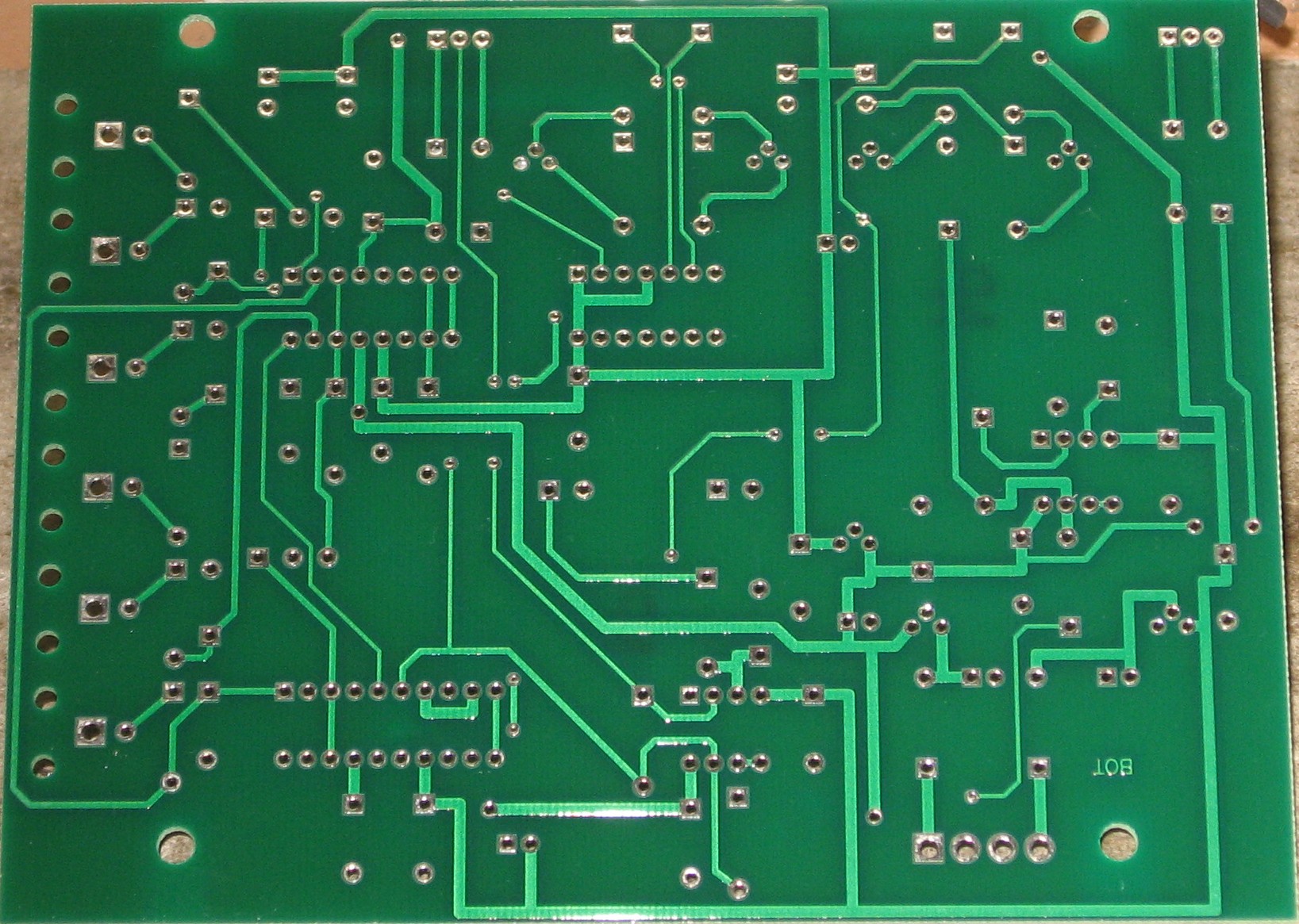
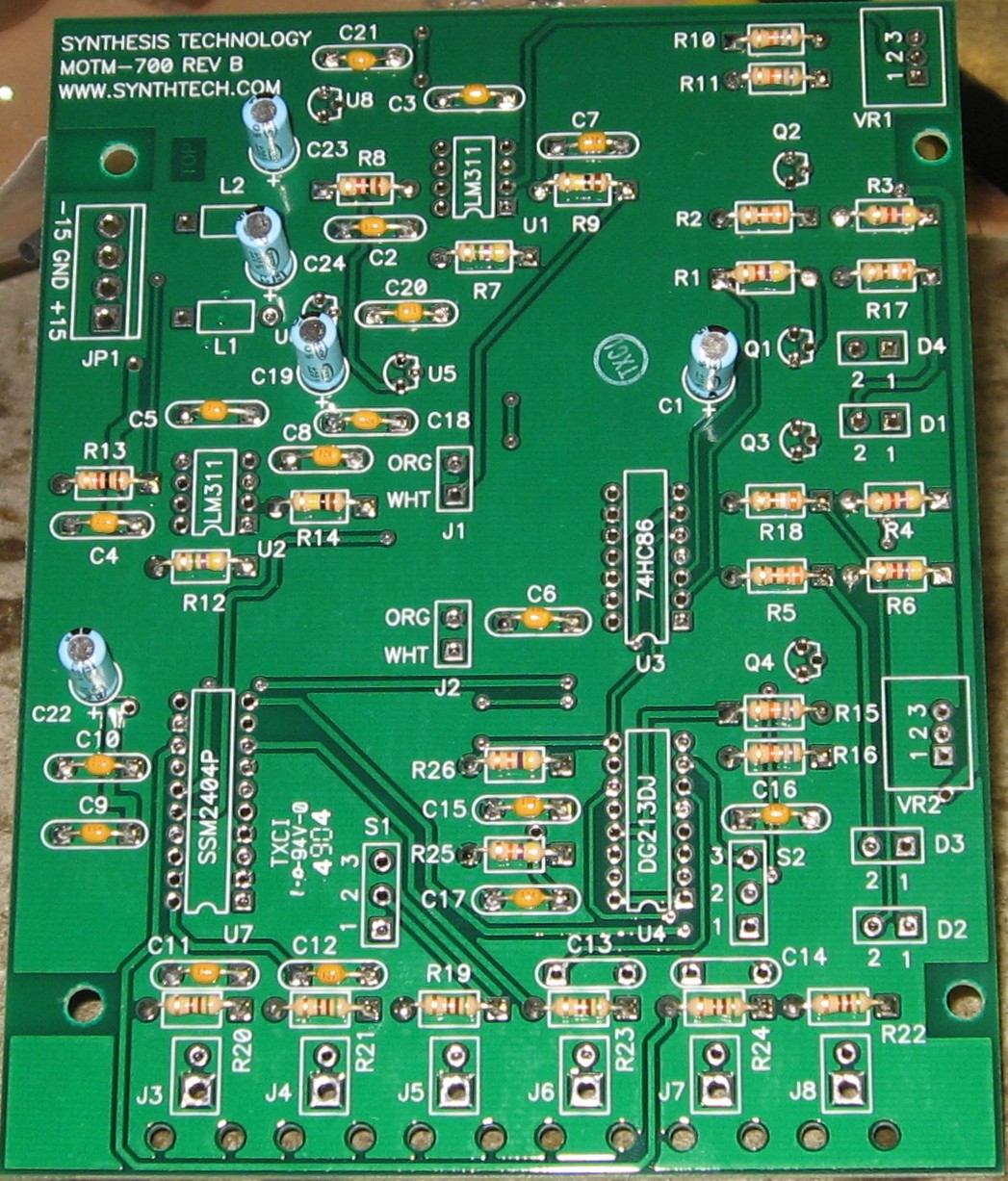
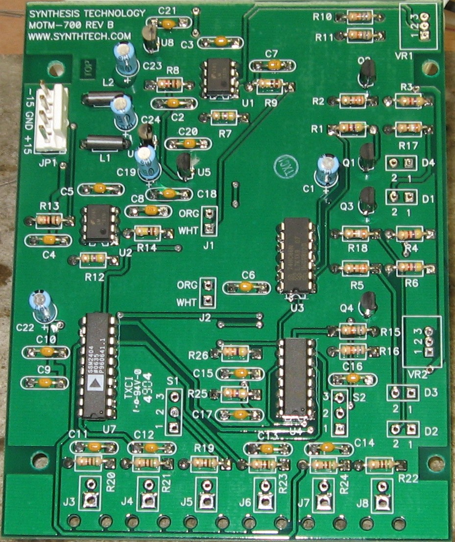
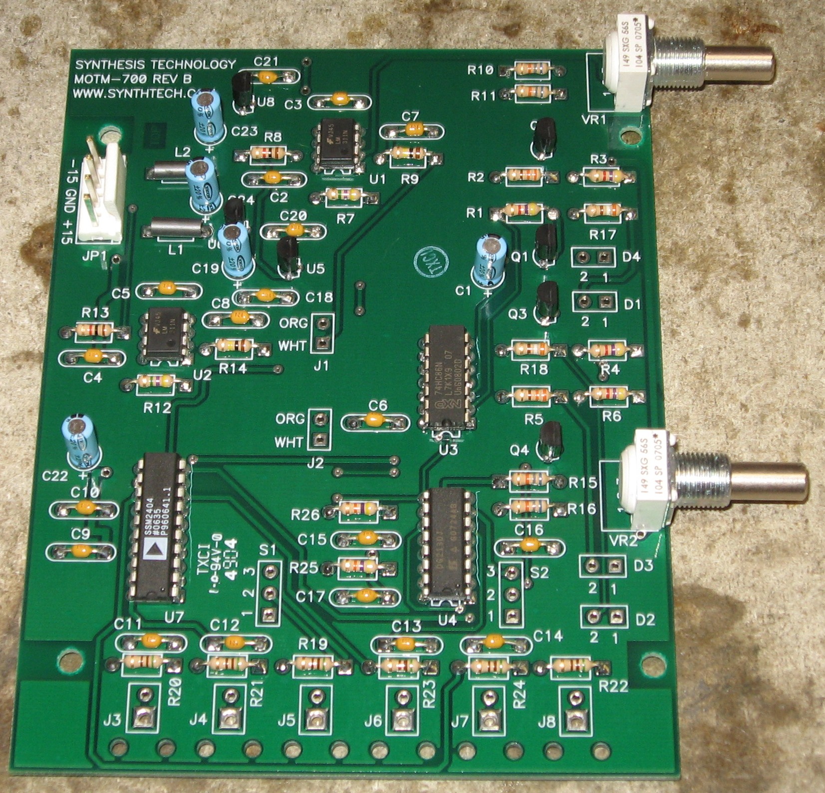
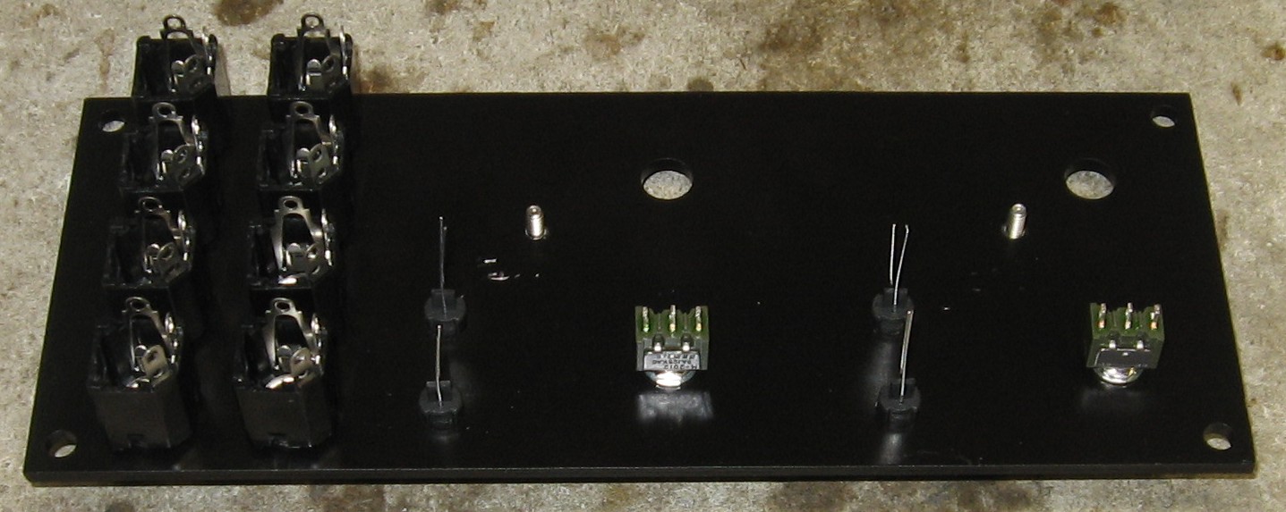
Construction Phase 1
All the stuff in Phase 1 gets soldered using "Organic" Solder. At every break in the action, we wash the board off to get rid of the flux. |
||
|
|
||
|
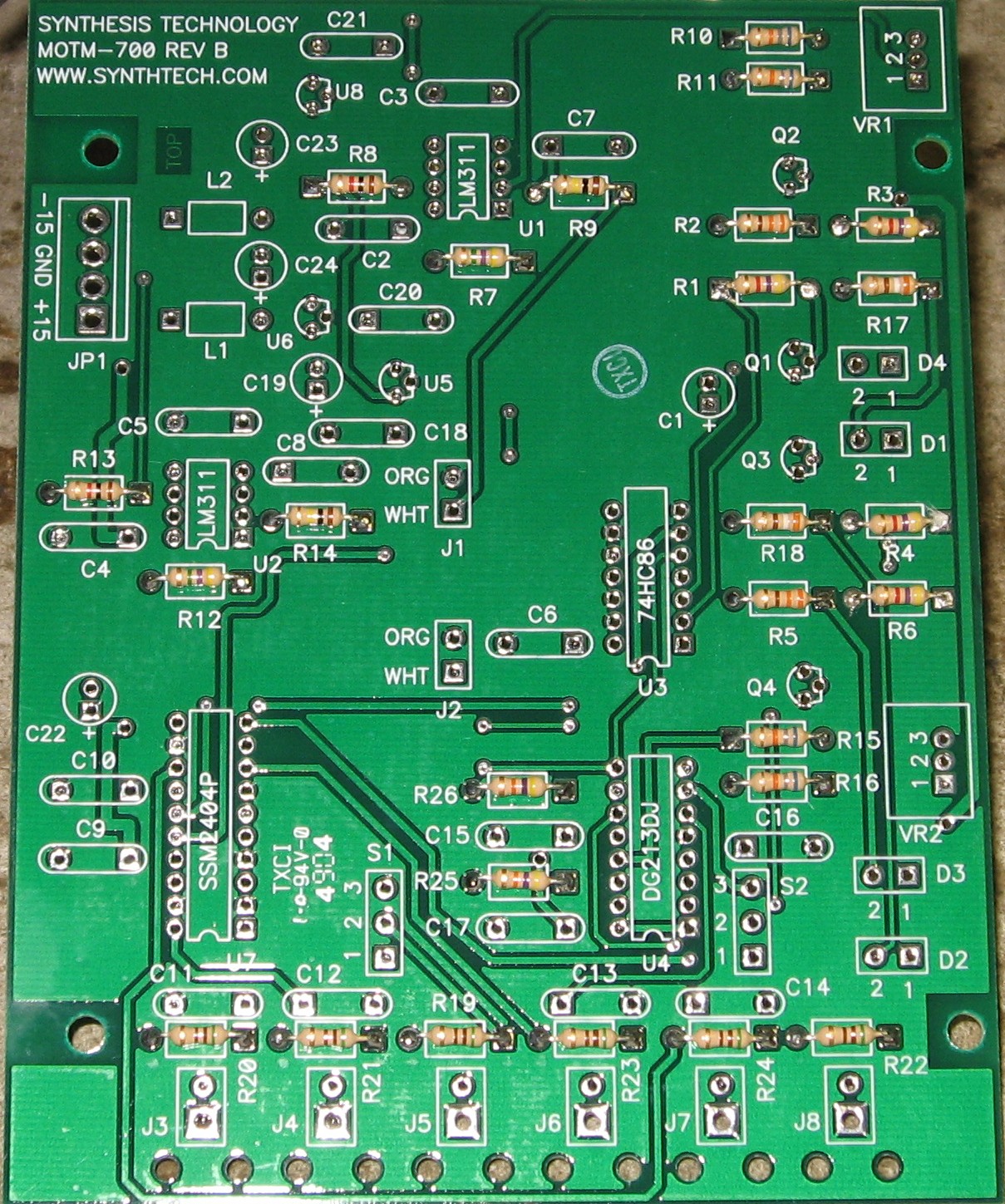
Resistors |
||
|
Our usual disclaimer: Whereas we are vigilant about orienting all the resistors, caps, etc. consistently so their values can be read easily (in case we need to trouble-shoot them later), we oriented the resistors with the "tolerance" stripe on the left (relative to the text on the pcb). Why did we do it this way? 'Cause when we started out doing these builds, we thought the gold stripe is so pretty and easy to see... and we put it on the left - well - just because. But now, we do it so all our modules are consistent with each other <shrug>. You might want to do it the opposite way - with the "tolerance" stripe on the right. |
||
|
Capacitors |
||
|
|
||
|
Semiconductors, ICs, Misc |
||
|
|
||
|
|
||
Construction Phase 2All the stuff in Phase 2 gets soldered using "No Clean" Solder. |
||
|
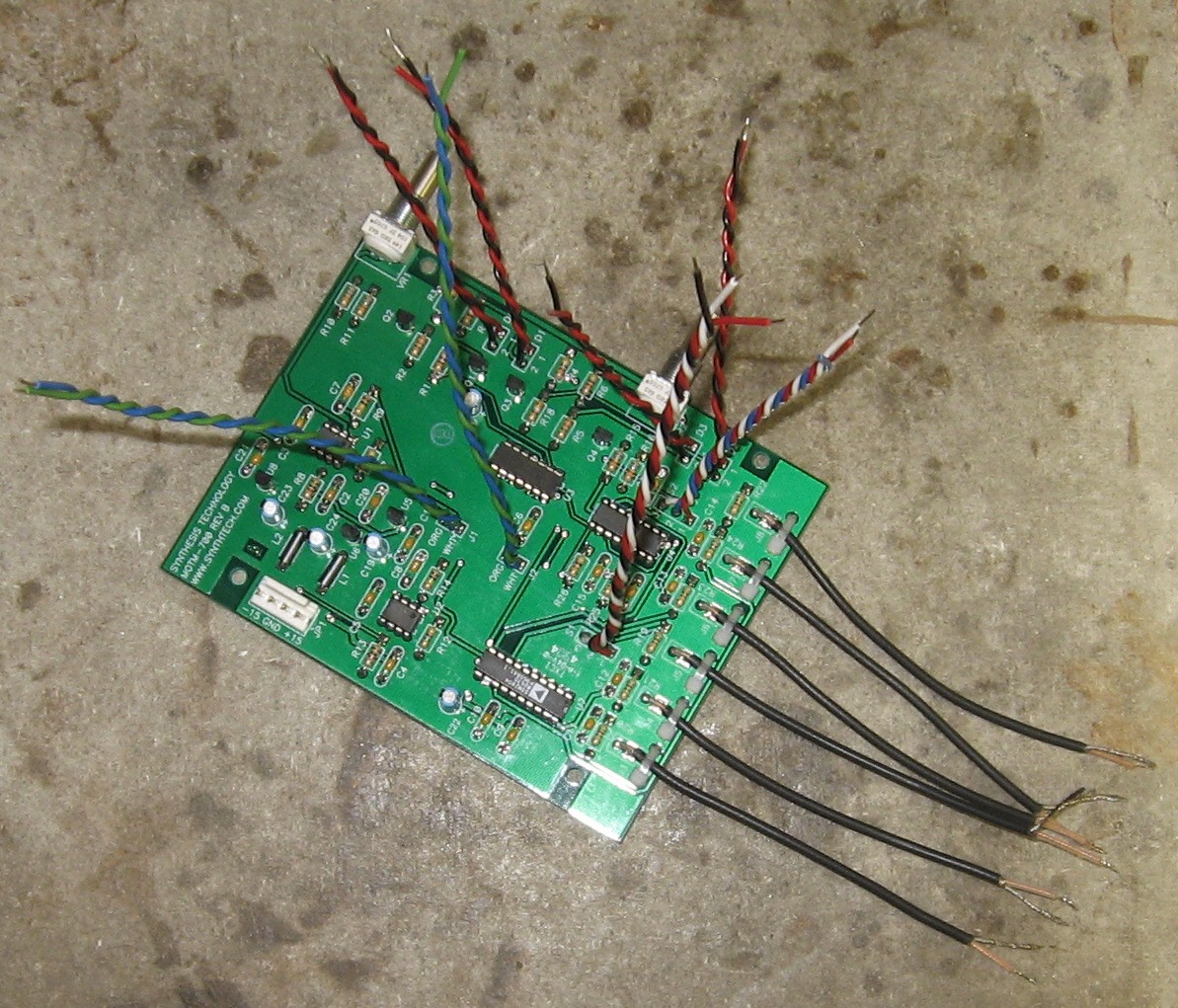
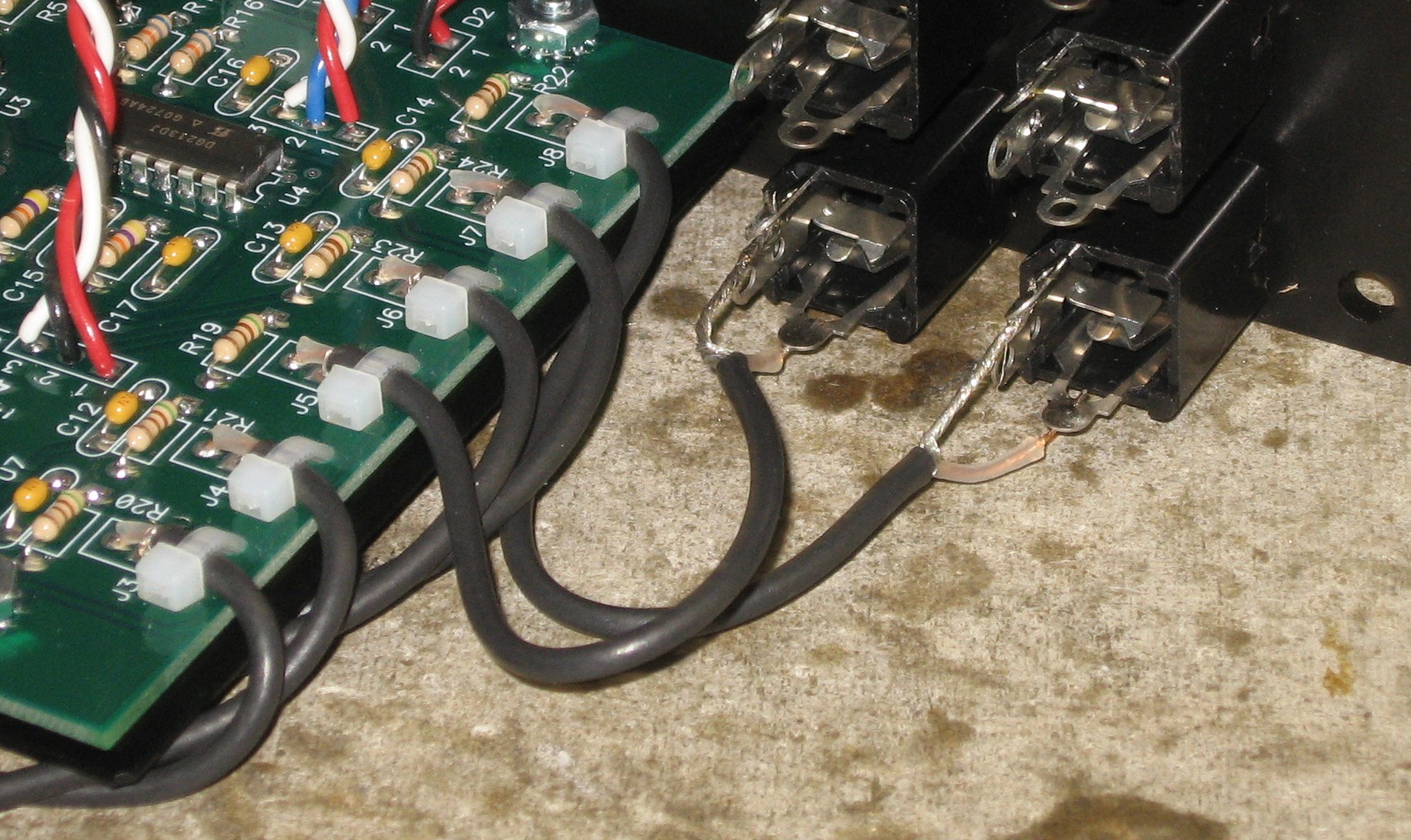
Prepare Wires |
||
|
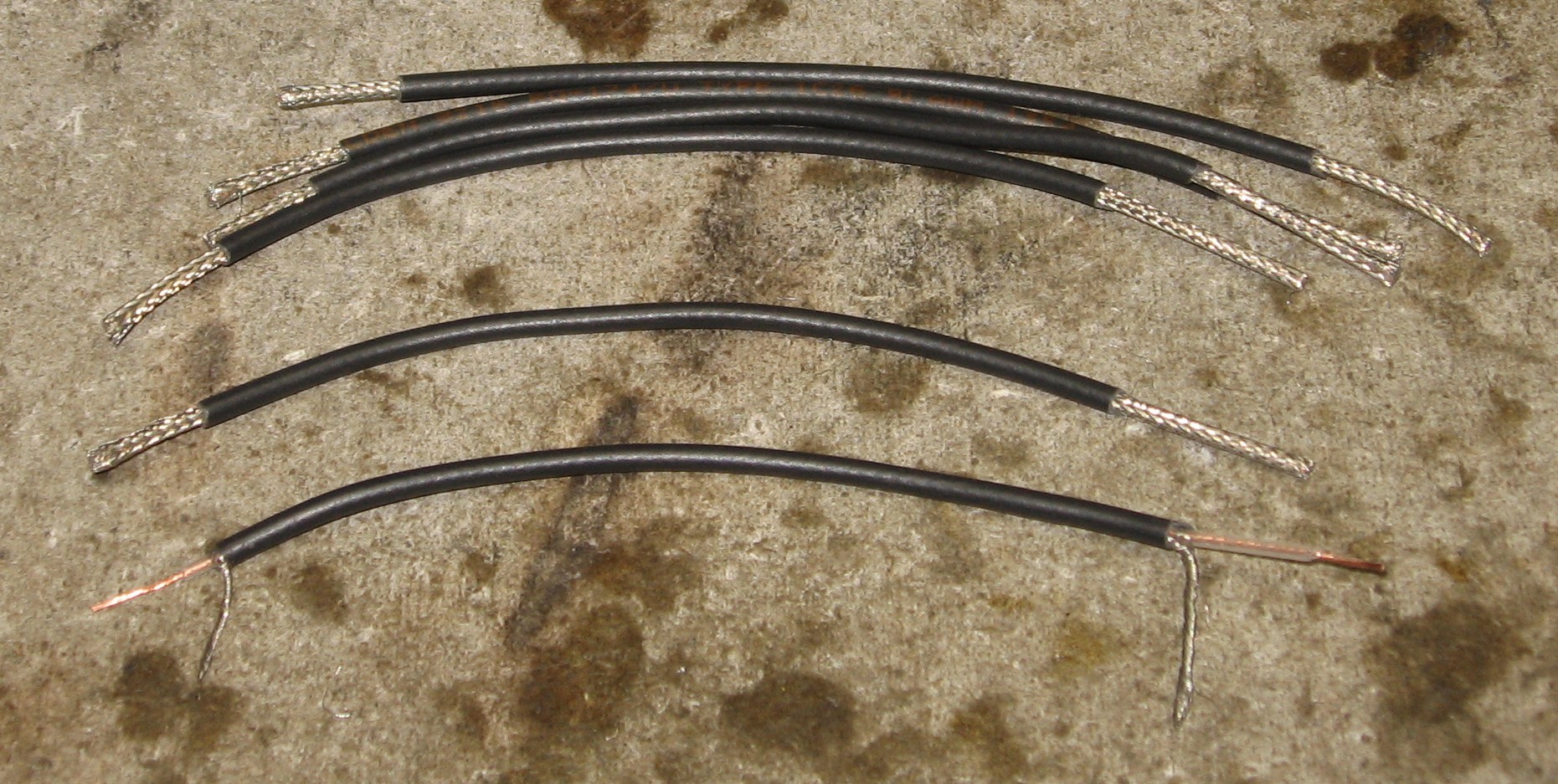
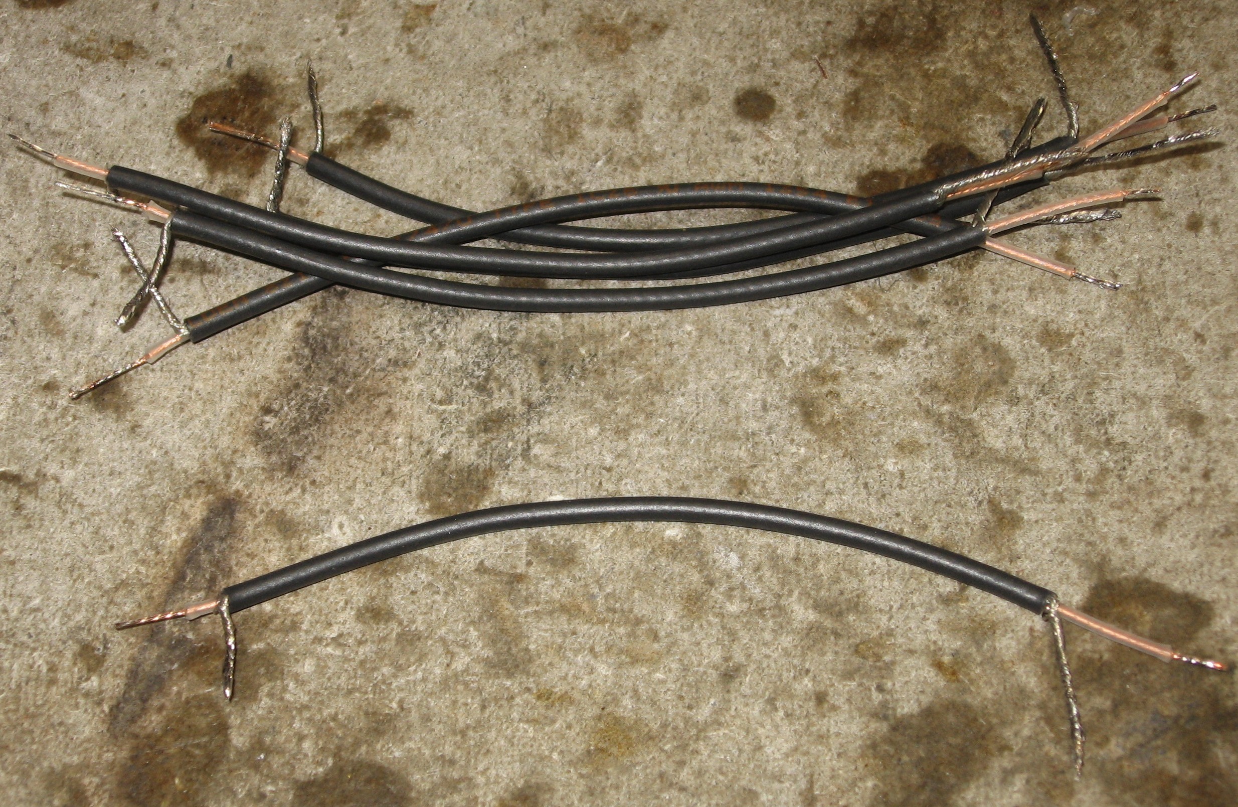
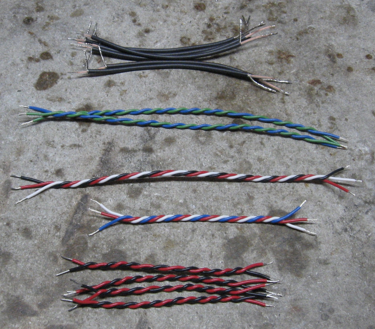
Paul's Assembly Instructions and User's Manual calls for a set of wires. If you bought them from Paul, then you're in like Flynn, but if you didn't (like us) you'll have to make up your own. Paul calls for six 4-1/2in. coax... well, we made them 5in. for good measure:
So then the rest of the wires:
|
||
|
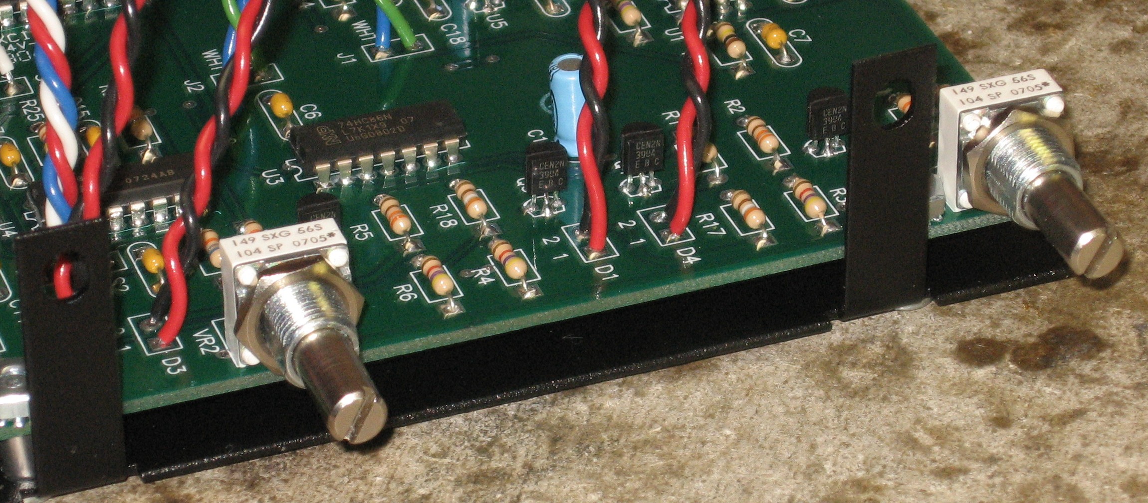
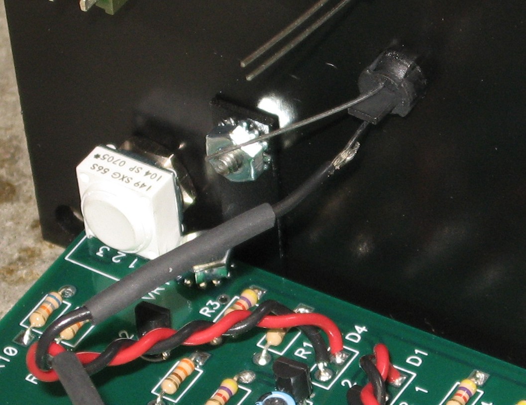
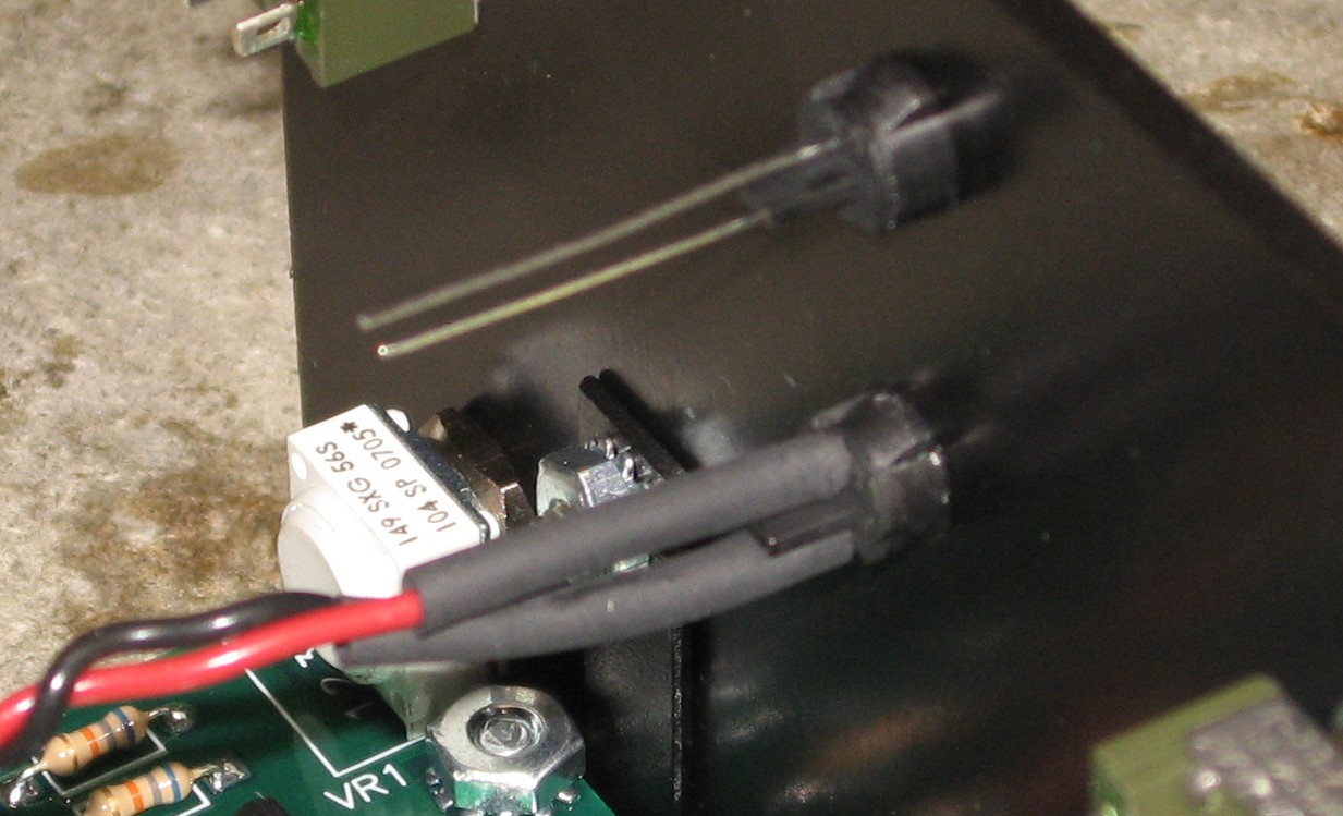
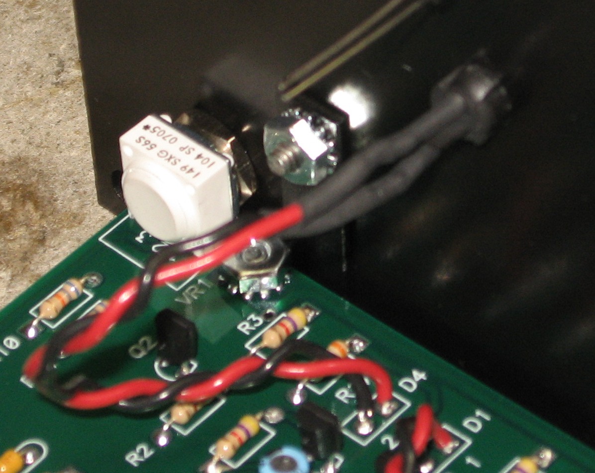
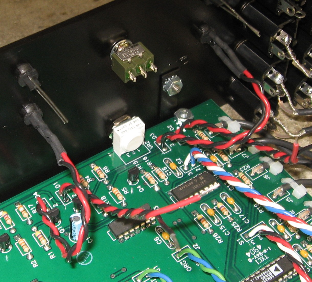
Pots |
||
|
|
||
|
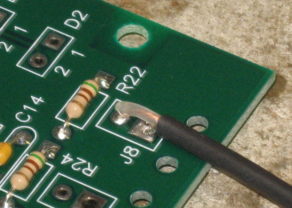
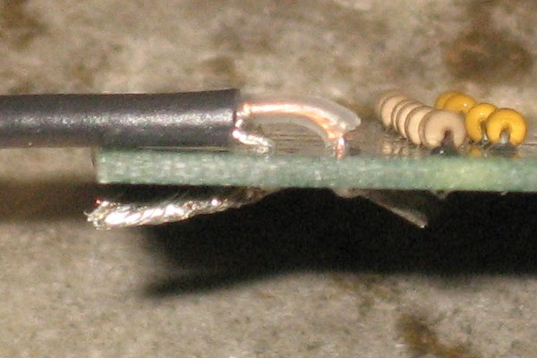
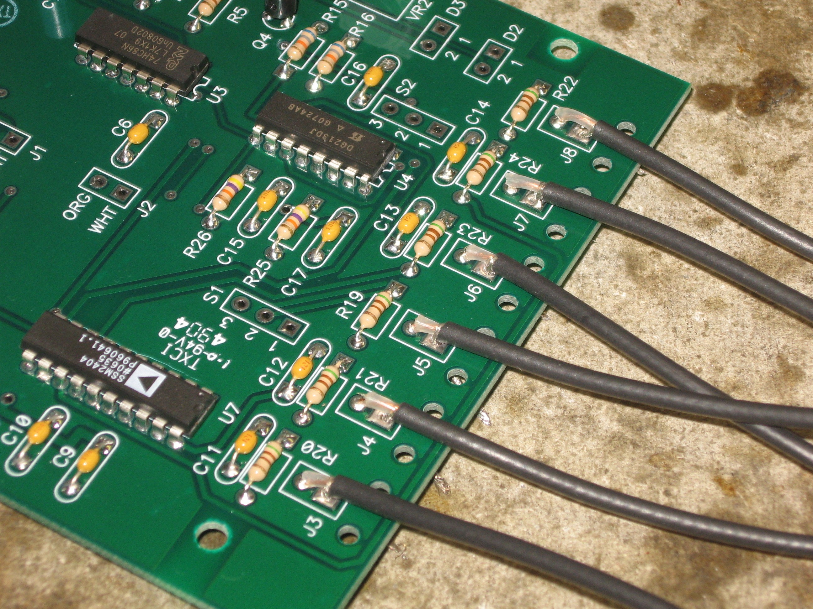
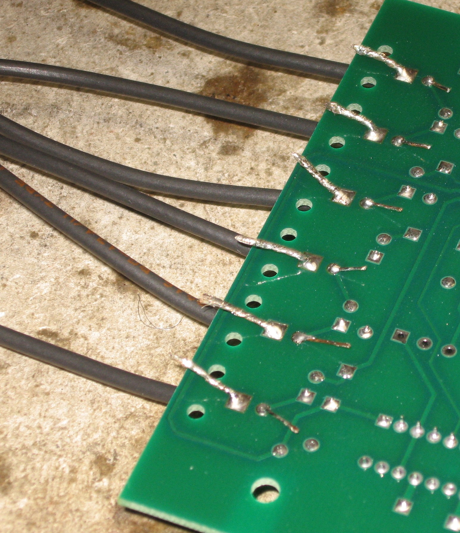
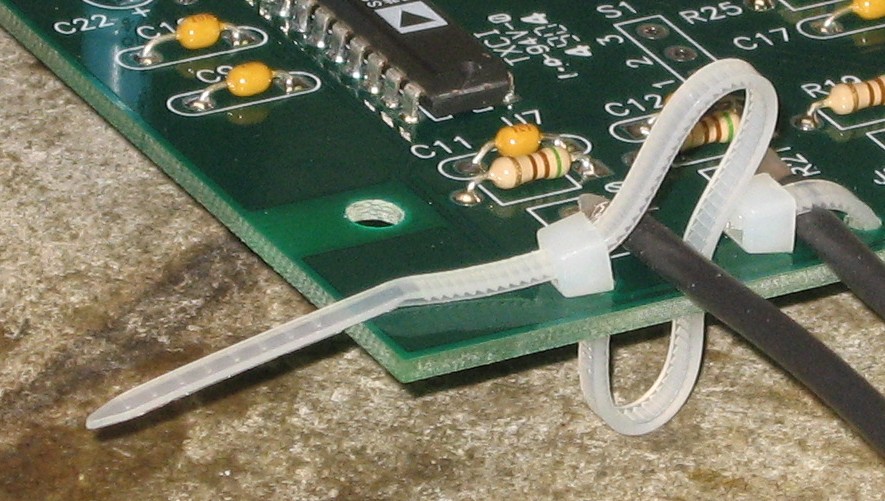
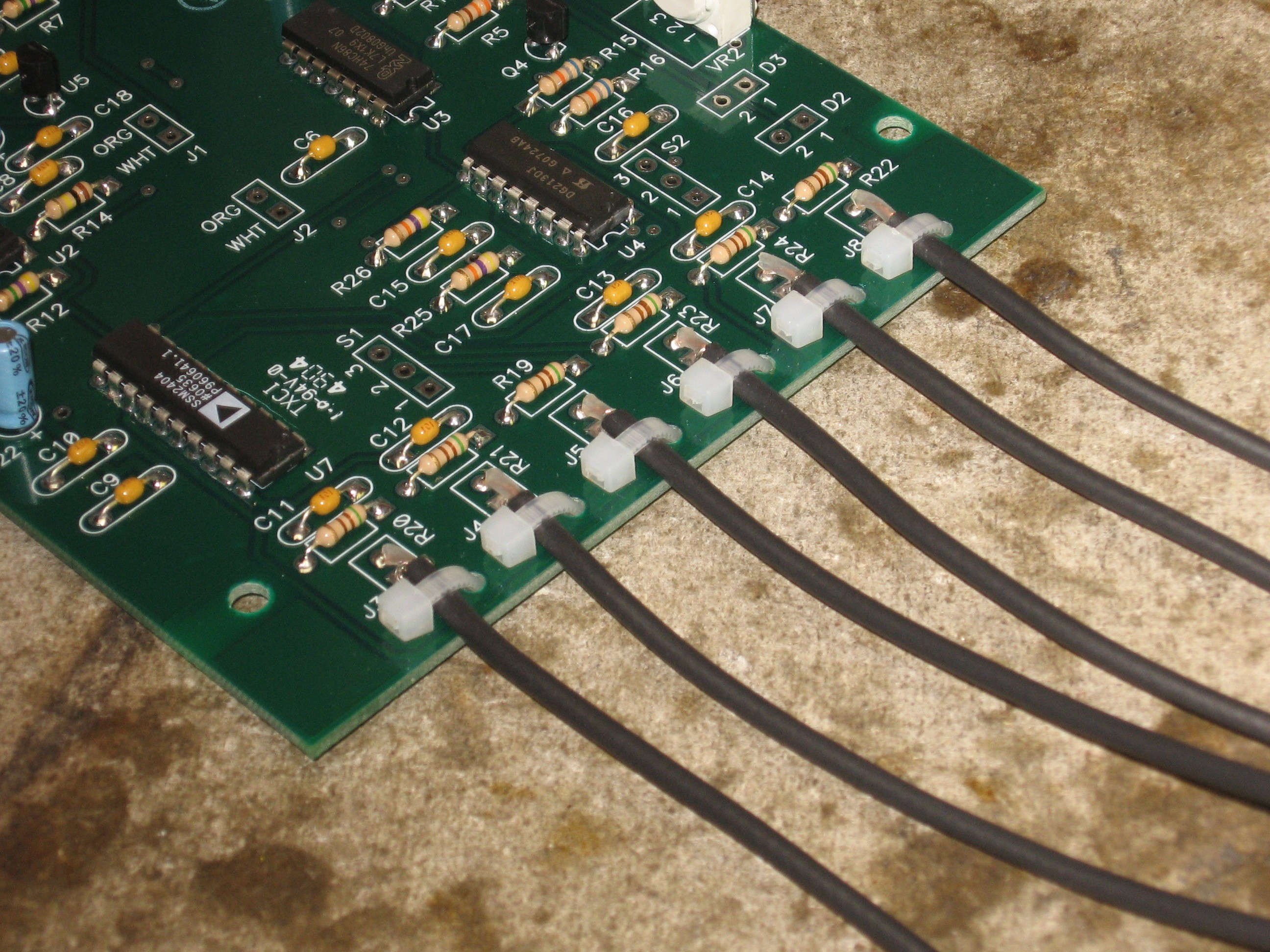
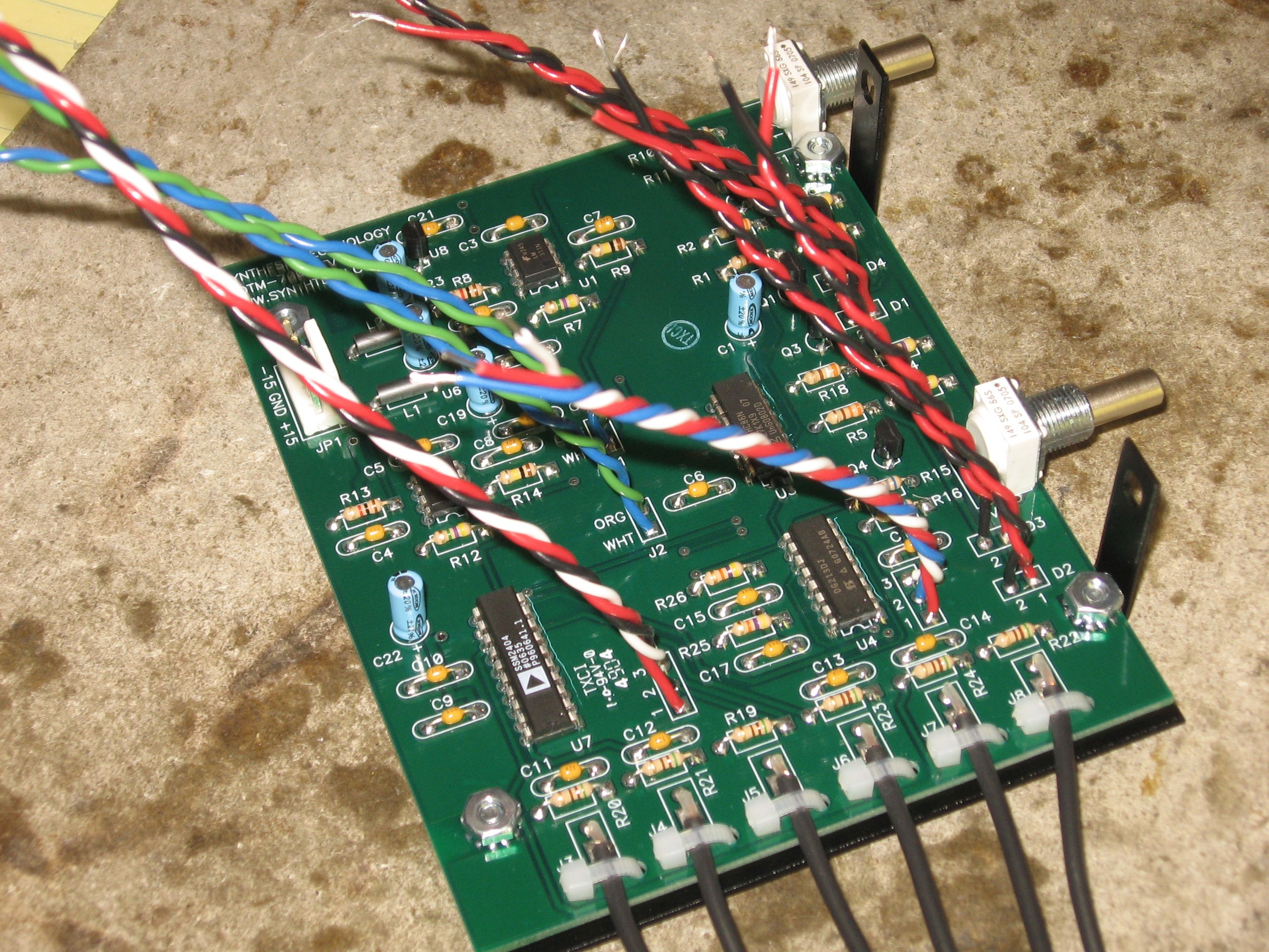
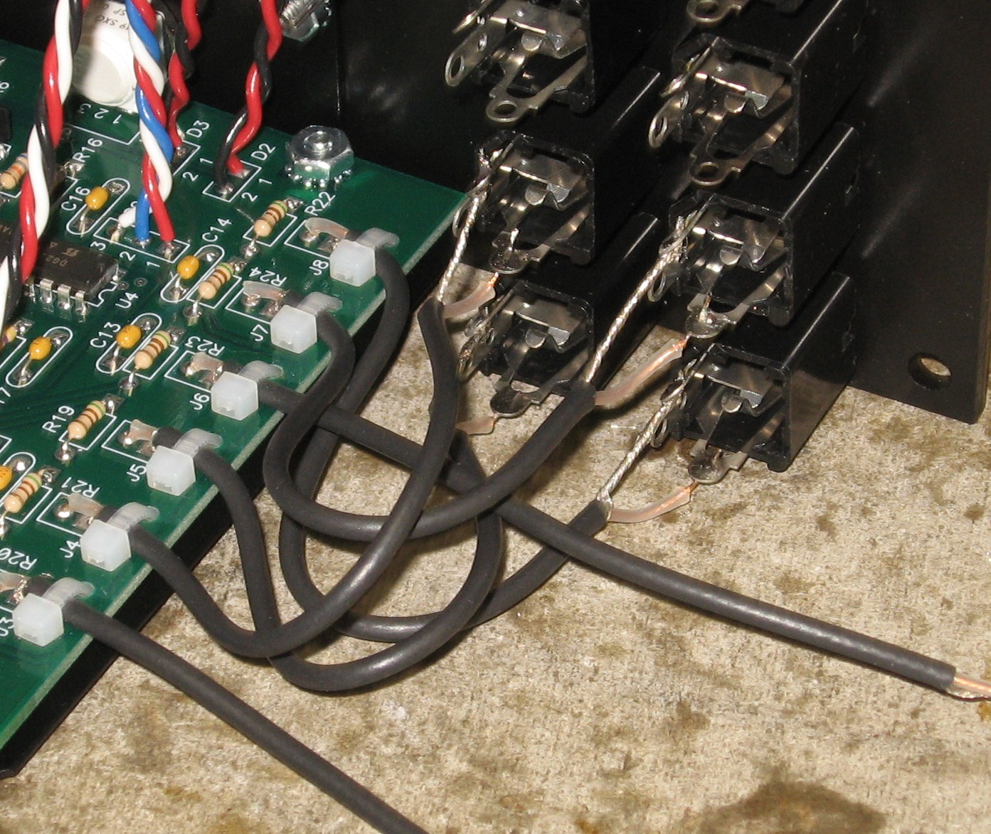
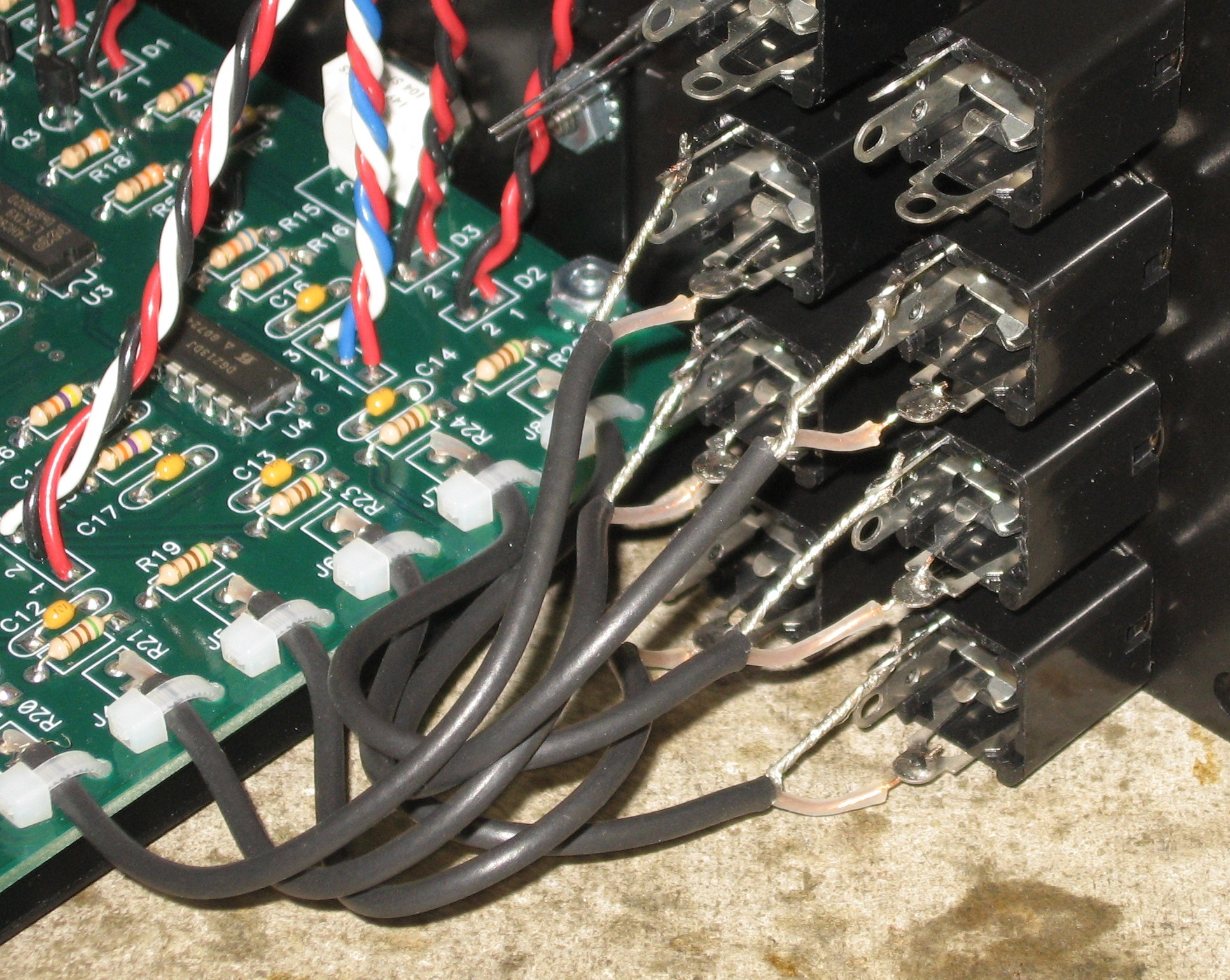
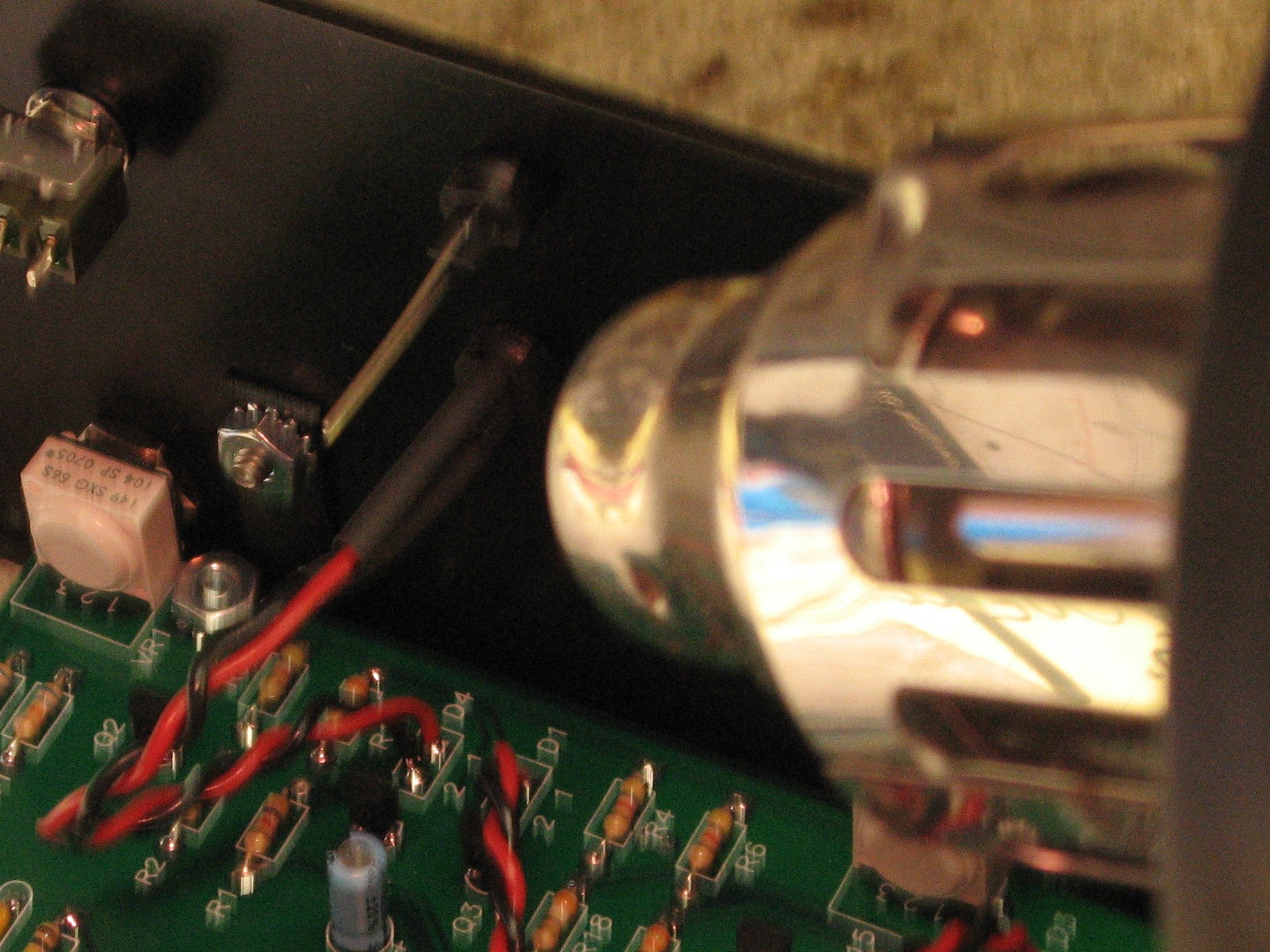
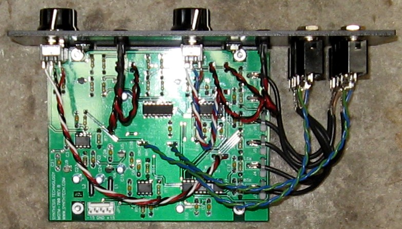
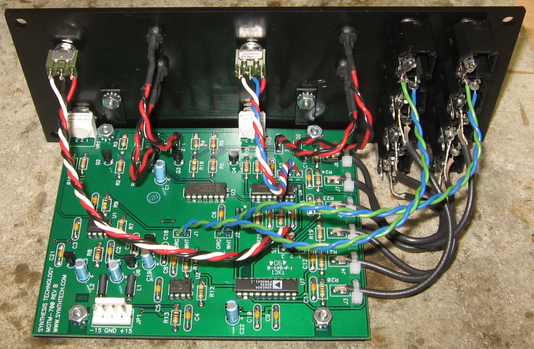
Wires Installed in the PCB |
||
|
Coax into PCB
Ties
Wires
|
||
|
Preparing the Panel |
||
|
Jacks
LEDs
Switches
|
||
|
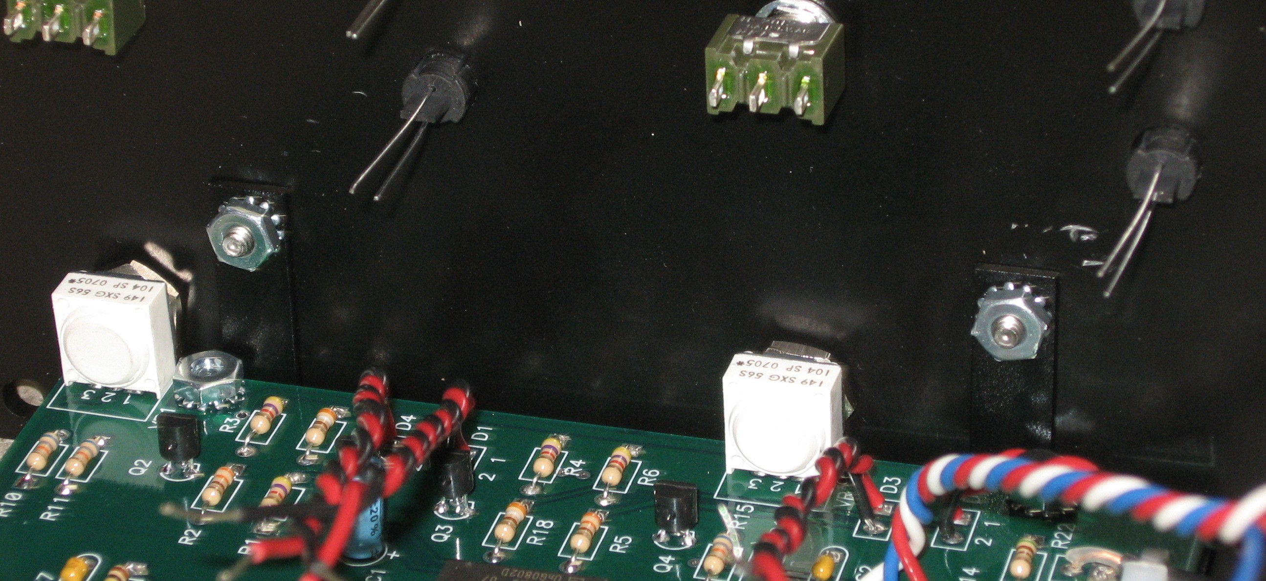
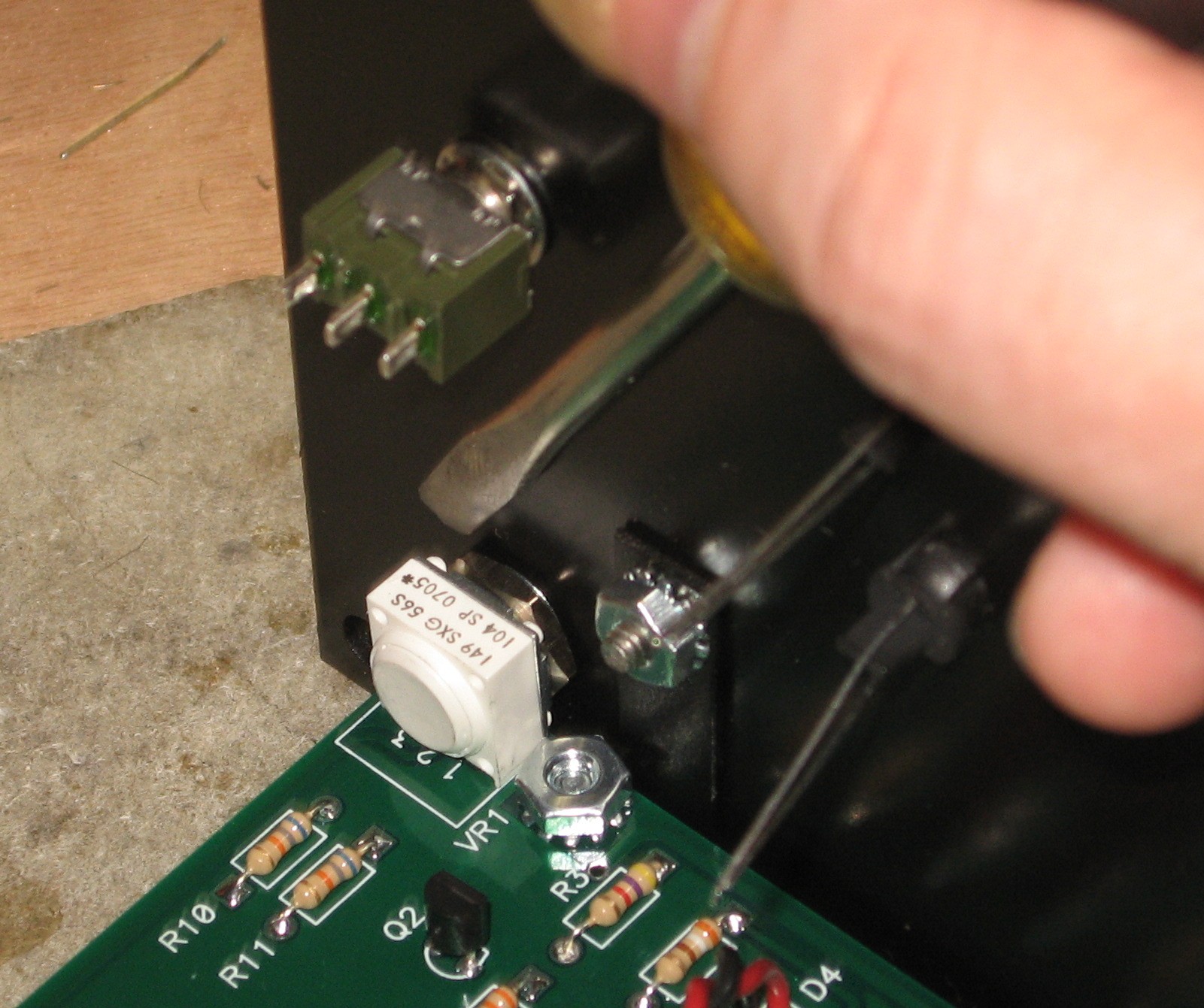
Mounting the PCB |
||
|
|
||
|
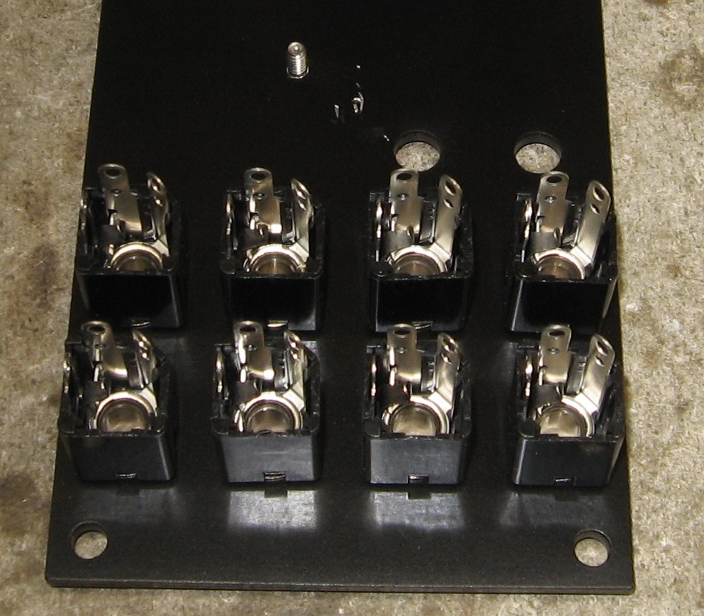
Input / Output Jacks |
||
|
|
||
|
LEDs |
||
|
|
||
|
Done |
||
|
|
||
Set up / Testing |
||
Use Notes |
||
|
|
||


|
The fine Print: Use this site at your own risk. We are self-proclaimed idiots and any use of this site and any materials presented herein should be taken with a grain of Kosher salt. If the info is useful - more's the better. Bill and Will © 2005-2011 all frilling rights reserved
|