Bill and Will's Synth
|
||
Table of Contents |
||
|
This page has become really long, so here's a table of contents that we hope will make it easier to traverse: Parts - presents a Bill of Materials for "two-dot-oh" builders and notes about it Panel - presents the MOTM format panel Construction Phase 1 - Resistors, Capacitors, IC Sockets, Power Plugs, MTA headers Construction Phase 2 - Trimmers, Panel connections |
||
Parts |
||
|
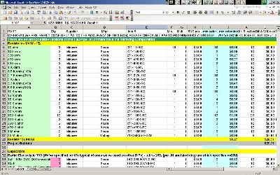
Will and I have developed a parts-list / bill-of-materials in the form of an XL spreadsheet based on the parts list in the 420 User Guide. Click here to download the XL spreadsheet (apx. 350K).
Click here to download the .pdf Synthesis Technology parts section of the User's Guide. Click here to go to our Bill of Materials Page. |
||
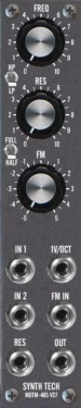
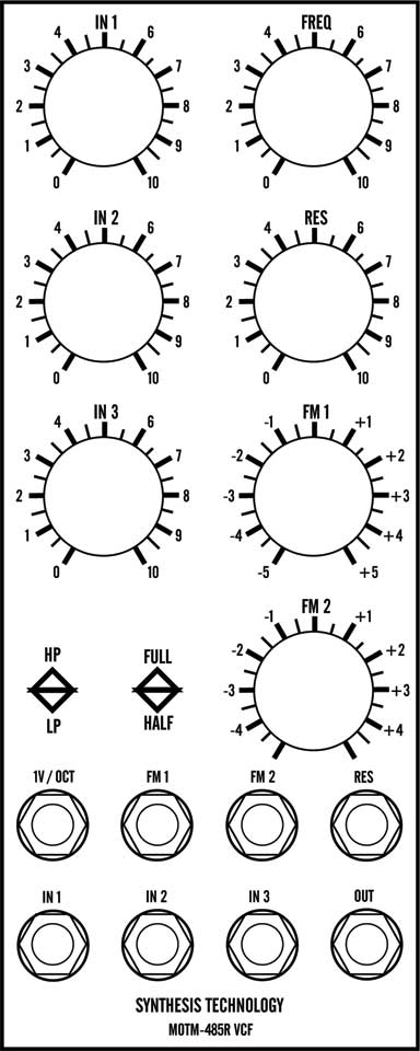
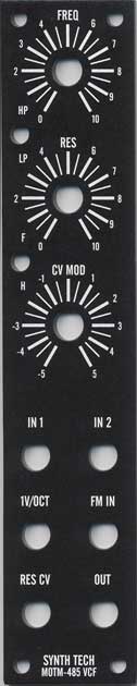
Panel |
||
|
If you're building this as a "two-dot-oh" project, we also assume you get the panel from Synthesis Technology:
|
||
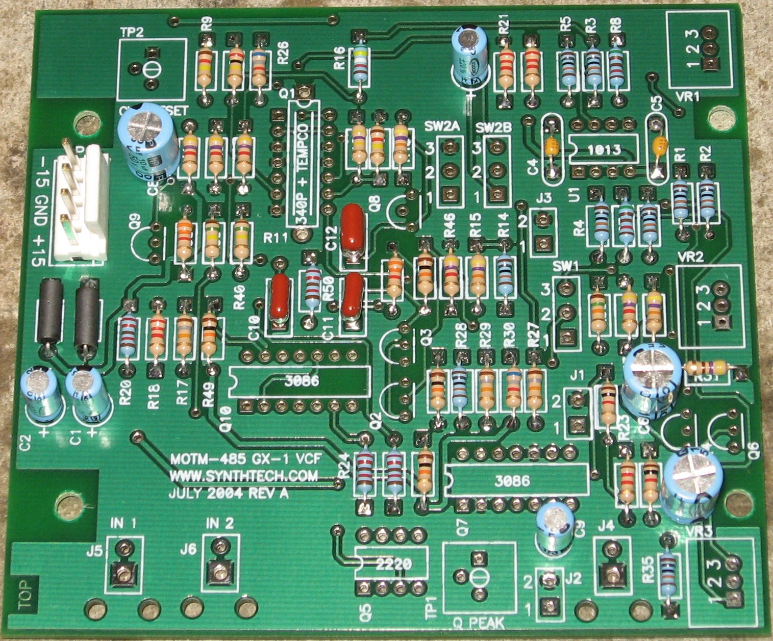
Construction Phase 1All the stuff in Phase 1 gets soldered using "Organic" Solder. At every break in the action, we wash the board off to get rid of the flux. |
||
|
Resistors, Caps, Power |
||
|
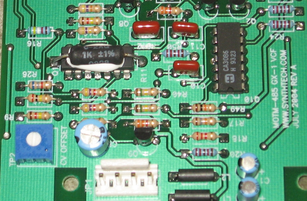
As usual, whereas we are vigilant about orienting all the resistors, caps, etc. consistently so their values can be read easily (in case we need to trouble-shoot them later), we oriented the resistors with the "tolerance" stripe on the left (relative to the text on the pcb). We got started doing it this way when we started building our synth and now we do it so all our modules are consistent with each other. You might want to do it the opposite way - with the "tolerance" stripe on the right. Some of the caps we got are a little fatter than their corresponding spots on the PCB, but we didn't have any trouble fitting them in. |
||
|
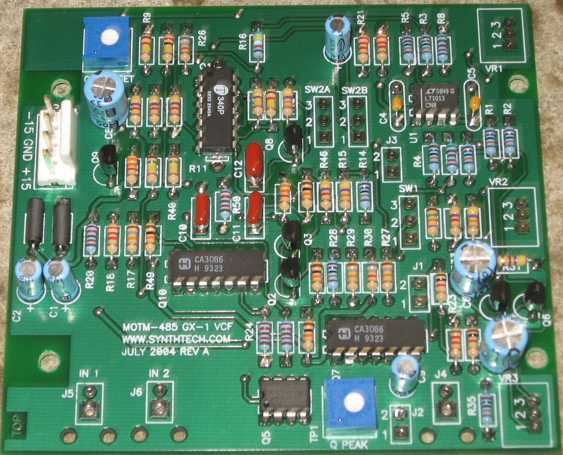
Semiconductors - Misc - Via Holes |
||
|
|
||
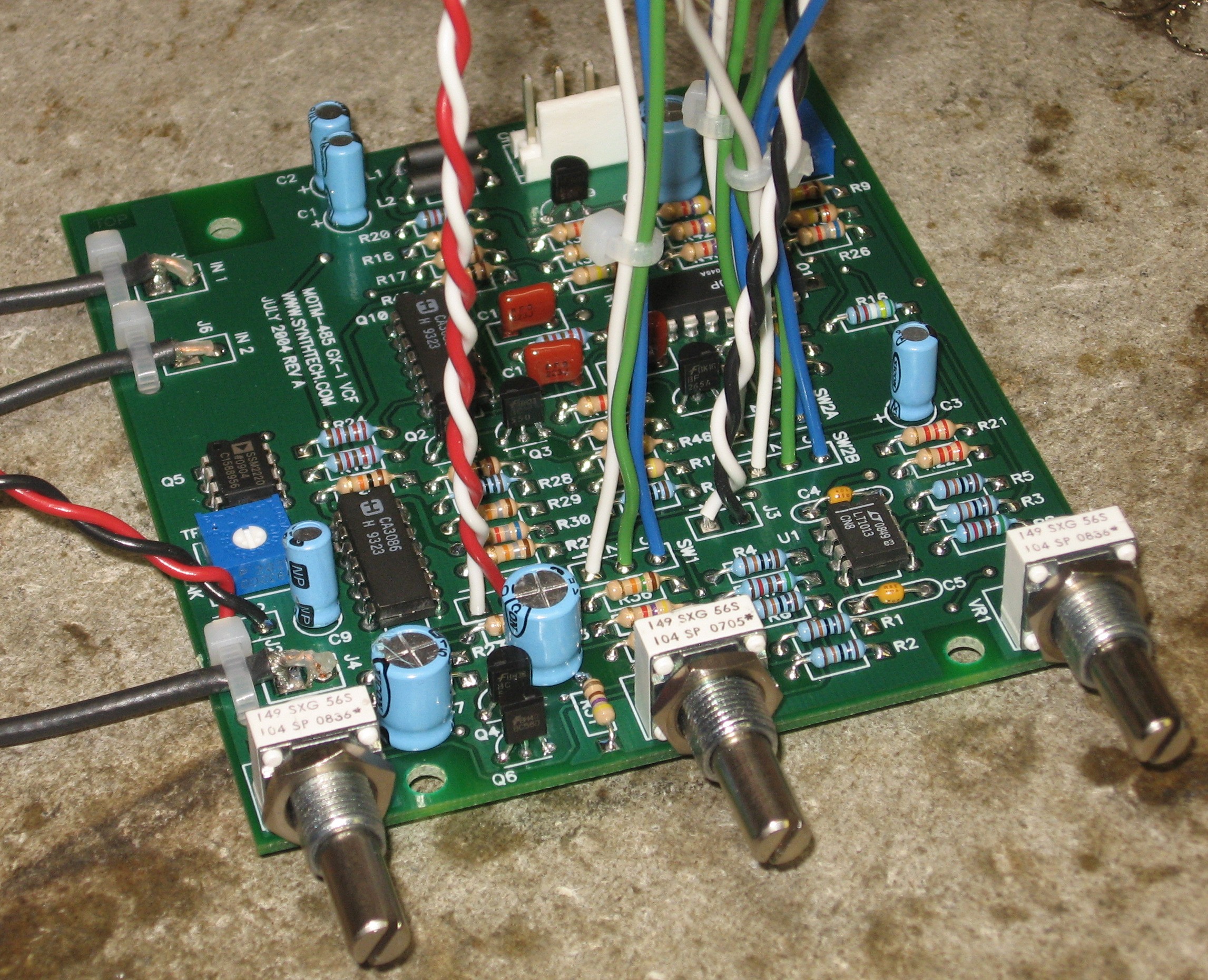
Construction Phase 2All the stuff in Phase 2 gets soldered using "No Clean" Solder. |
||
|
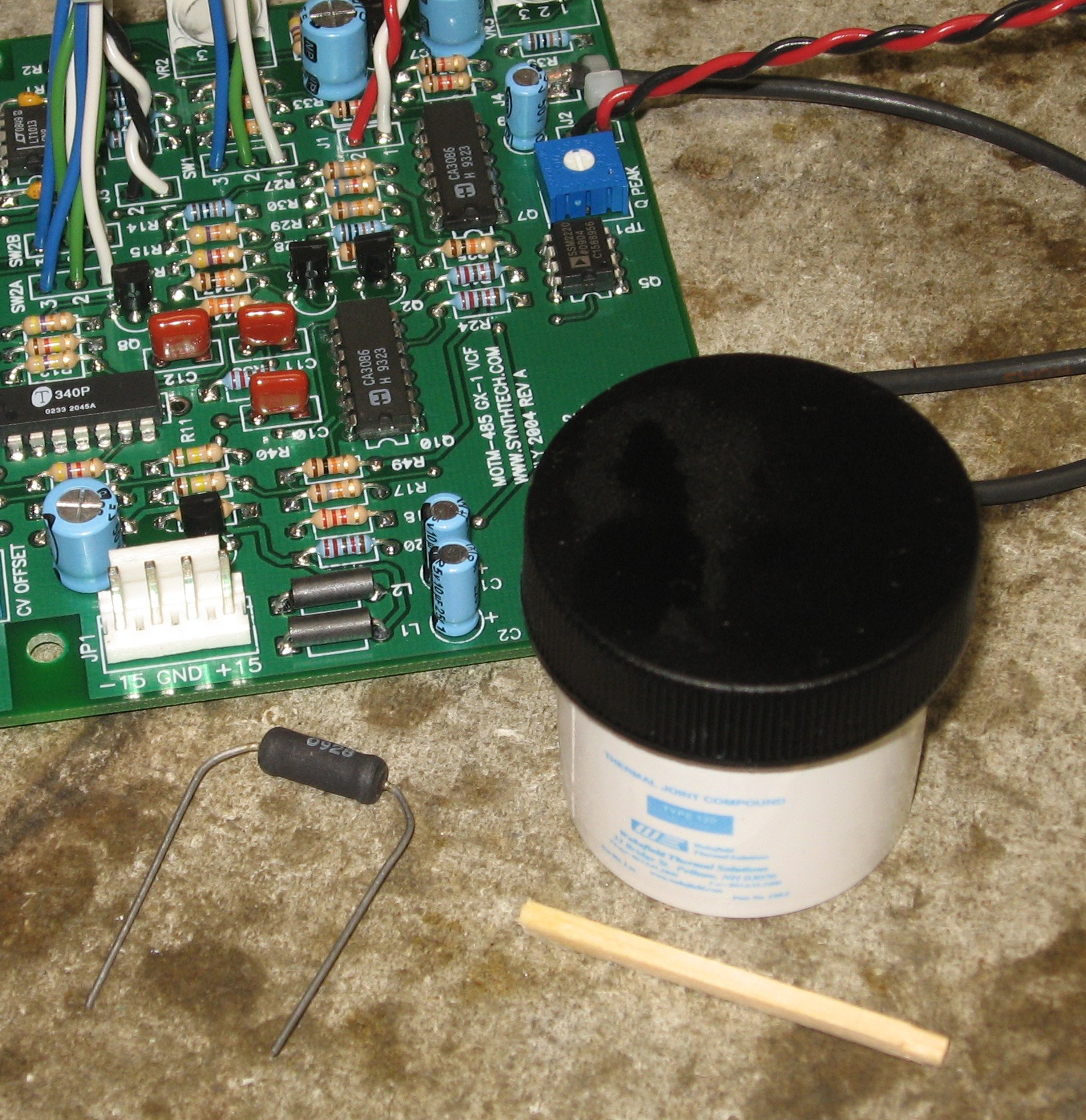
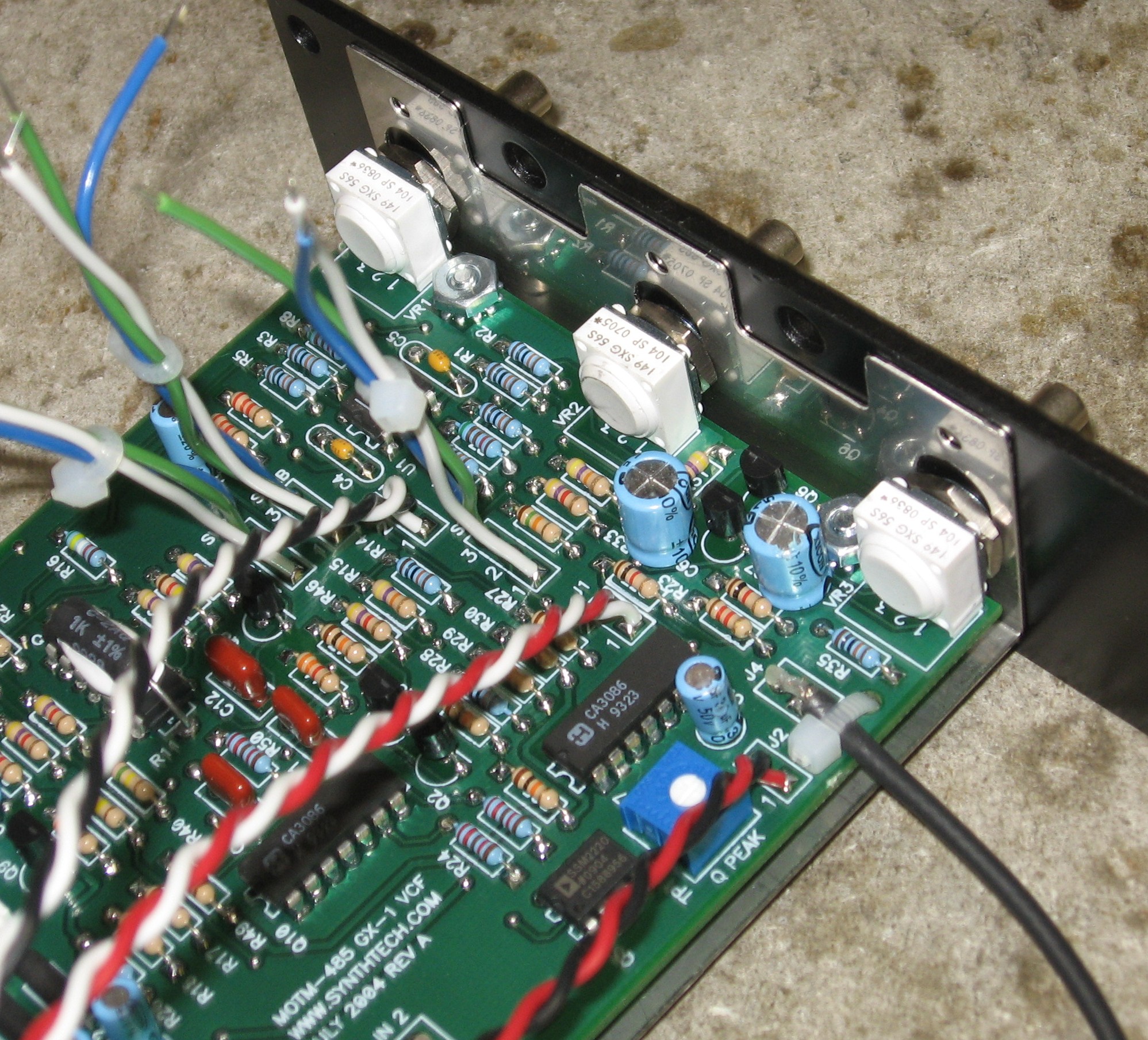
Pots, Temco, Wires |
||
|
|
||
|
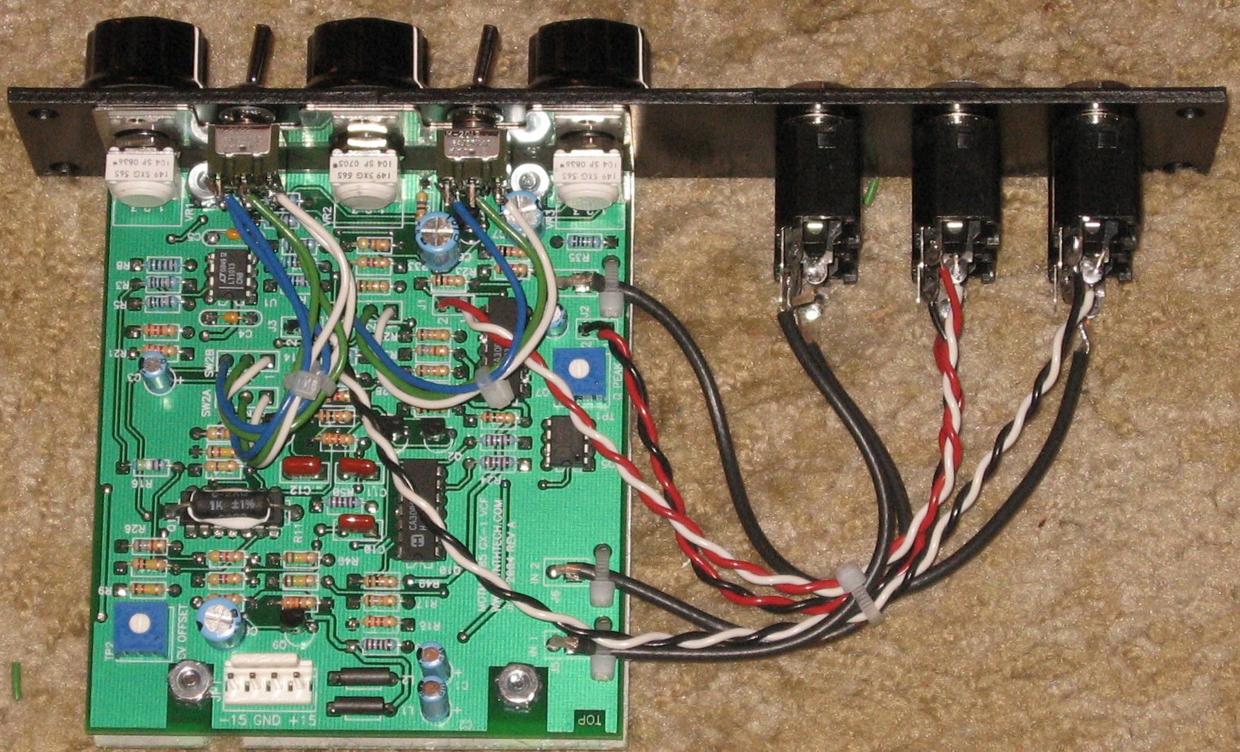
Mounting the PCB |
||
|
|
||
|
Construction Done |
||
|
|
||
Set up / Testing |
||
Use Notes |
||
|
|
||
|
The fine Print: Use this site at your own risk. We are self-proclaimed idiots and any use of this site and any materials presented herein should be taken with a grain of Kosher salt. If the info is useful - more's the better. Bill and Will © 2005-2011 all frilling rights reserved
|