Bill and Will's Synth
|
|
Table of Contents |
|
|
This page has become really long, so here's a table of contents that we hope will make it easier to traverse: Parts - presents a Bill of Materials for "two-dot-oh" builders and notes about it Panel - presents the MOTM format panel Construction Phase 1 - Resistors, Capacitors, IC Sockets, Power Plugs, MTA headers Construction Phase 2 - Trimmers, Panel connections |
|
Parts |
|
|
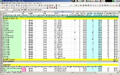
OK - so - In 2008 (or about that time), Synthesis Technology stopped producing full-blown kits, and moved toward what Paul calls "2.0" (two-dot-oh) DIY. This assumes the builder will buy certain parts from Synthesis Technology - PCB, Panel, and in some cases a Special Parts Kit of the particularly hard to find parts - and will get the rest of the parts from Mouser or Digikey or - well - wherever. For those who are building this as a "two-dot-oh" project, Will and I, with feedback and review from others, have developed a parts-list / bill-of-materials in the form of an XL spreadsheet (as usual). Please don't take it as gospel. We've been over and over it and are relatively confident in our specifications - and we hear that several people have used it successfully so you should be good. The BOM assumes that you get the "extra parts kit" from Synthesis Tech. Synthesis Technology offers some parts like pots and knobs at particularly good prices... these options are offered in the BOM.
Click here to download our XL spreadsheet Parts List |
|
Panel |
|
|
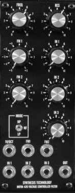
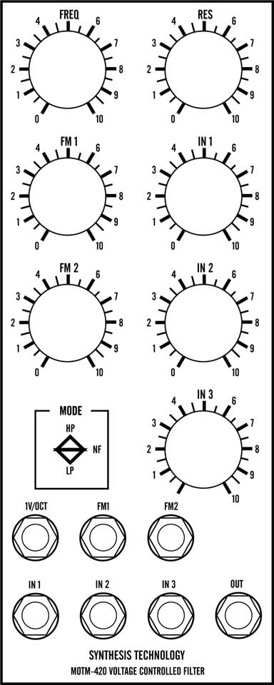
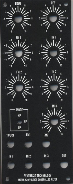
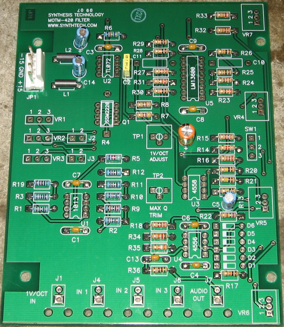
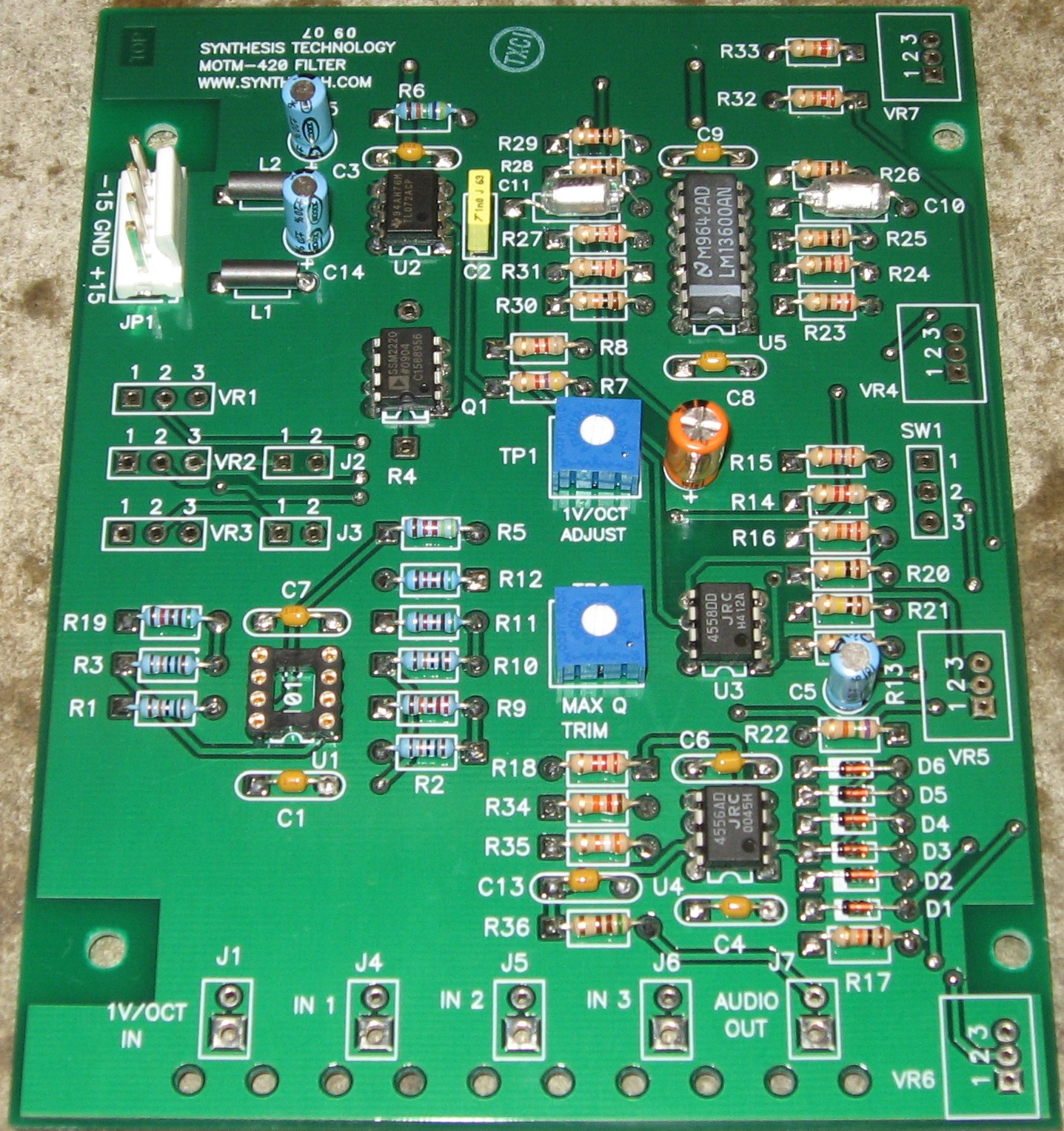
If you're building this as a "two-dot-oh" project, we also assume you get the panel from Synthesis Technology:
|
|
Construction Phase 1All the stuff in Phase 1 gets soldered using "Organic" Solder. At every break in the action, we wash the board off to get rid of the flux. |
|
|
Resistors, Caps, Power |
|
|
As usual, whereas we are vigilant about orienting all the resistors, caps, etc. consistently so their values can be read easily (in case we need to trouble-shoot them later), we oriented the resistors with the "tolerance" stripe on the left (relative to the text on the pcb). We got started doing it this way when we started building our synth and now we do it so all our modules are consistent with each other. You might want to do it the opposite way - with the "tolerance" stripe on the right. One of the caps we got is a little fatter than its corresponding spot on the PCB, but we didn't have any trouble fitting it in. |
|
|
Semiconductors - Misc - Via Holes |
|
|
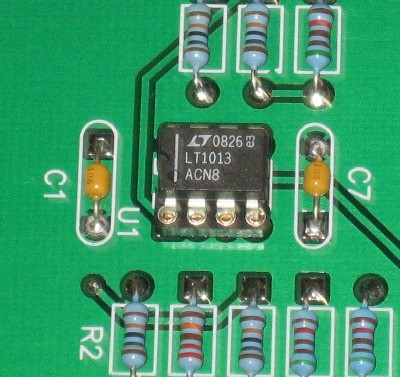
We used an IC jack for the 1013 op amp 'cause we weren't totally sure the one we got is correct. Here it is installed in the jack:
|
|
Construction Phase 2All the stuff in Phase 2 gets soldered using "No Clean" Solder. |
|
|
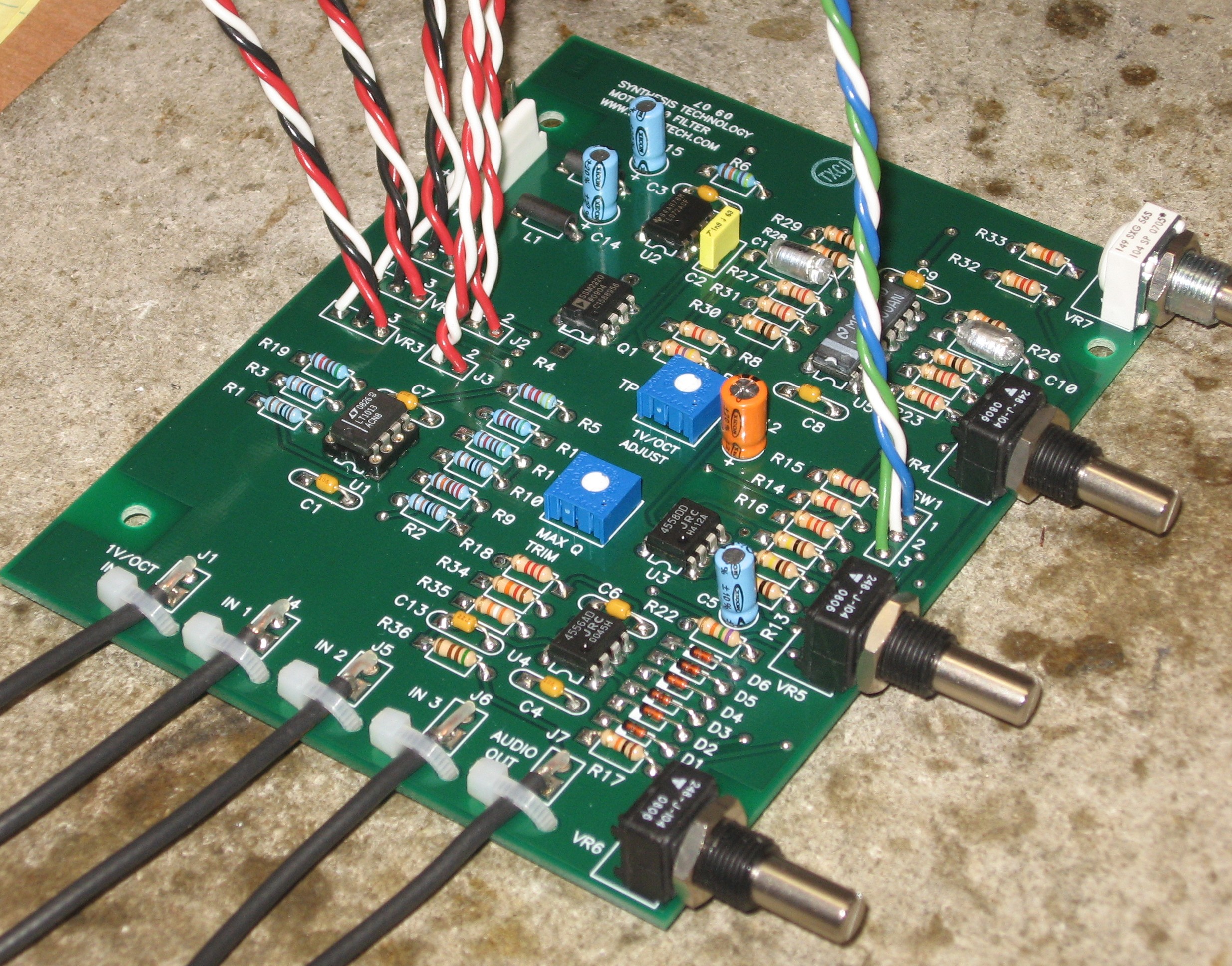
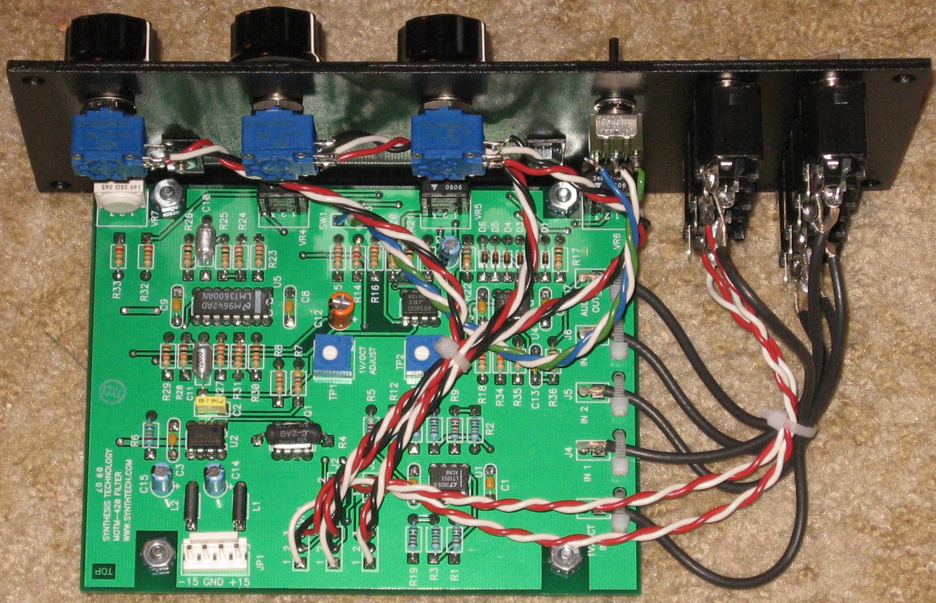
Pots, Wires |
|
|
|
|
|
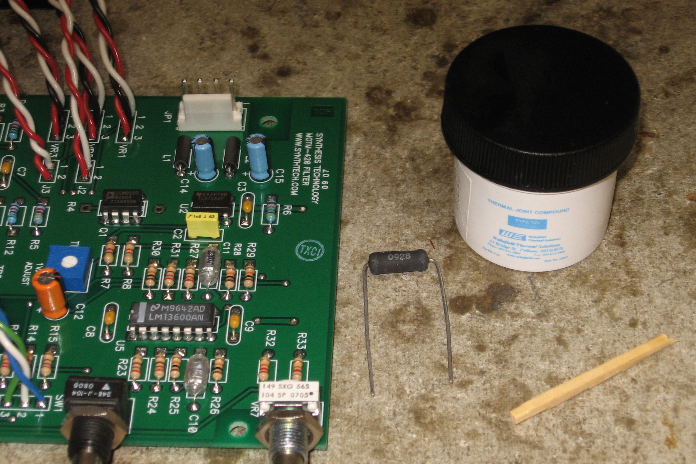
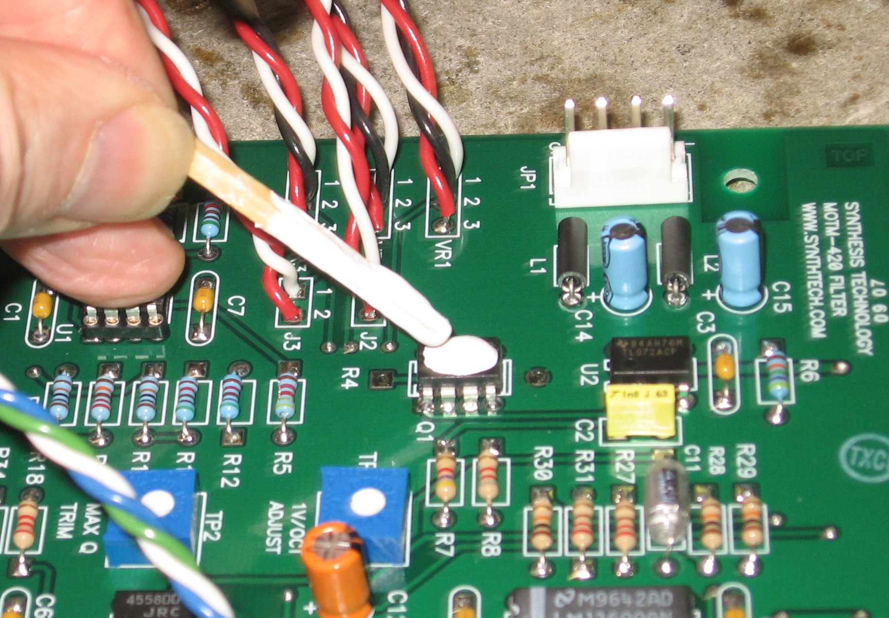
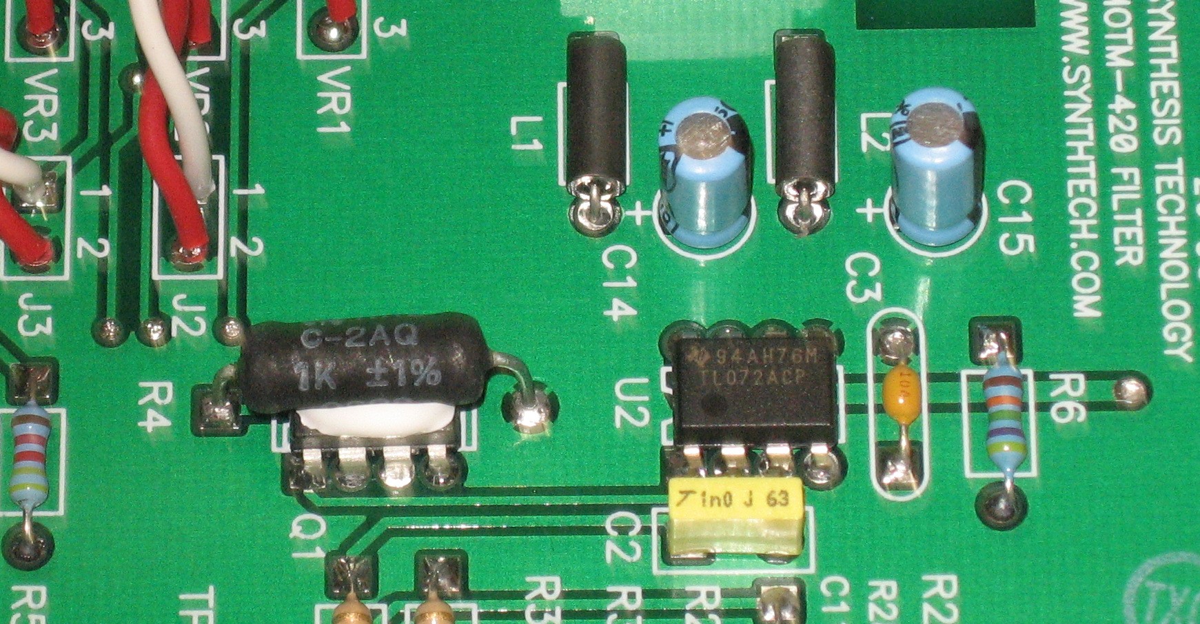
Tempco Resistor |
|
|
|
|
|
Construction Done |
|
|
|
|
Set up / Testing |
|
Use Notes |
|
|
|
|
The fine Print: Use this site at your own risk. We are self-proclaimed idiots and any use of this site and any materials presented herein should be taken with a grain of Kosher salt. If the info is useful - more's the better. Bill and Will © 2005-2011 all frilling rights reserved
|