Bill and Will's Synth
|
|||||||||||||||||||||||||||
|
|||||||||||||||||||||||||||
|
June 2007 - The MOTM 320 has a "difficulty factor" of 3, but we're going to include the Richard Brewster / Scott Juskiw 320 Daughter Board in our construction so it's probably more difficult. Doug Wellington (SynthPanels.com) may have a "320R Stooge Panel" ready someday soon - and if so, that'd be really great. Scott Deyo of Bridechamber included the 320R in his January 2008 panel run. We're getting two from him. He may have some left over. In case he doesn't, however, Richard Brewster gave us a "FPD" file which is the design and specs for a "Front Panel Express" 320R-type panel we're including it here in case someone needs it. Down side of an FPExpress Panel: more expensive - and the finish might match MOTM panels less well. Up side: might get it sooner. Doug Wellington sent us the 4-pot "Stooge Mounting Bracket" we'll need. The current implementation of the 320DB (Scott's PCB isn't now available) involves the "MUUB4" or "the Multi-Use Universal Buffer" board - a PCB developed by Richard Brewster, Larry Hendry, and Scott Juskiw and available through Scott's Tellun Industries. |
|||||||||||||||||||||||||||
Table of Contents |
|||||||||||||||||||||||||||
|
This page has become really long, so here's a table of contents that we hope will make it easier to traverse: Background - presents an explanation and Paul Schrieber's initial description of the Module with a couple photos from Larry Hendrey Modifications - presents details of Larry Hendry's Fine Tune Modification and Paul Haneburg's Tracking Adustment Parts - presents two Bills of Materials - one for "two-dot-oh" builders of the 320 and one for those who want to include the Tellun 320 Modifications - and notes about them Panel - presents the MOTM format panels Construction Phase 1 - Resistors, Capacitors, IC Sockets, Power Plugs, MTA headers Construction Phase 2 - Trimmers, Panel connections |
|||||||||||||||||||||||||||
Background |
|||||||||||||||||||||||||||
|
Paul Writes: "The MOTM-320 is a full-featured Voltage-Controlled Low-Frequency Oscillator (VC LFO). Unlike the crude LFOs found in most synths, the MOTM-320 has 4 individual outputs plus a master SHAPE control. This control voltage will shift the shapes of the Pulse, Sine, and Saw outputs in unison. Both 1 volt/octave (temperature compensated!) and variable FM (through a reversing attenuator to go up or down) inputs are available. "Another unique feature is a SYNC input: a positive voltage will reset all 4 waveforms. You can sync to just about any waveform: from another LFO to EG's. "The MOTM-320 is not your standard cheap LFO: it has a full-blown VCO core with discrete waveshaping based on the Moog modular and the VCS3! The core has an astounding frequency range of 1 cycle in 30 minutes to about 2800Hz. A bi-color LED flashes at the LFO rate, and can be set with a jumper to indicate 4 different ways! "Don't sacrifice a VCO as a full-featured LFO: get the MOTM-320 and let the modulations begin!" |
|||||||||||||||||||||||||||
Modifications |
|||||||||||||||||||||||||||
|
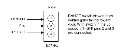
Per Scott Juskiw: "The DB-320, implemented using a MUUB-4, is a daughterboard for the MOTM-320 Voltage Controlled LFO. The DB-320 is intended to be used with the Stooge Panels 320R panel. The DB-320 adds inverted outputs for the four LFO waveforms. A header is also provided for connecting the RANGE switch on the MOTM-320R panel... "The User Guide explains how the MUUB-4 can be used to recreate the functionality of the discontinued DB-320 daughterboard that adds inverted outputs to the MOTM-320 LFO."
But we're going to detail the modifications here for our fellow idiots: |
|||||||||||||||||||||||||||
|
320DB Background |
|||||||||||||||||||||||||||
|
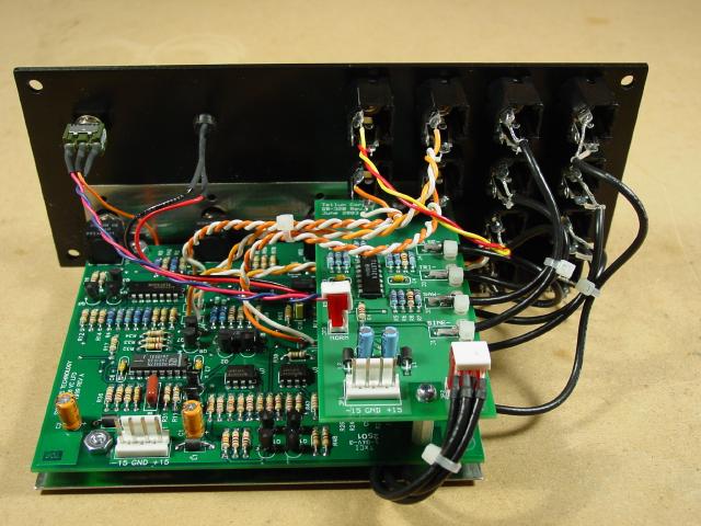
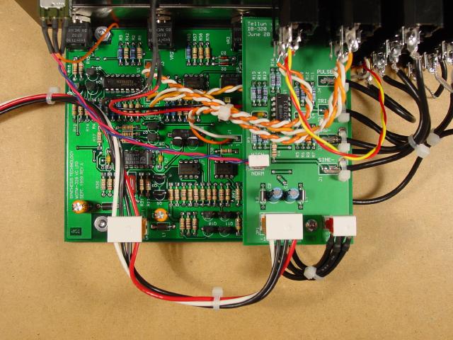
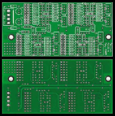
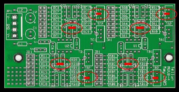
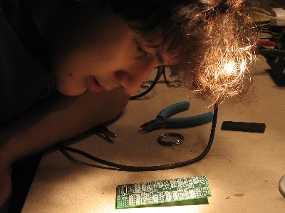
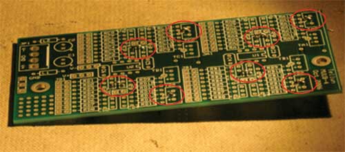
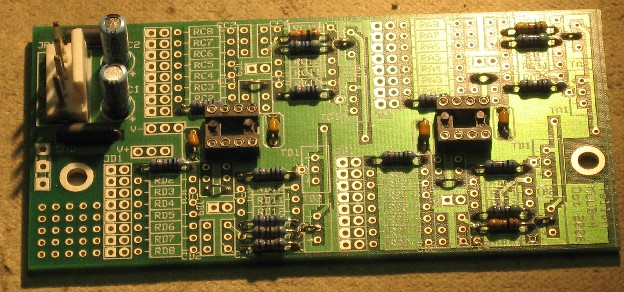
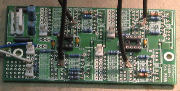
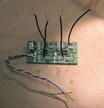
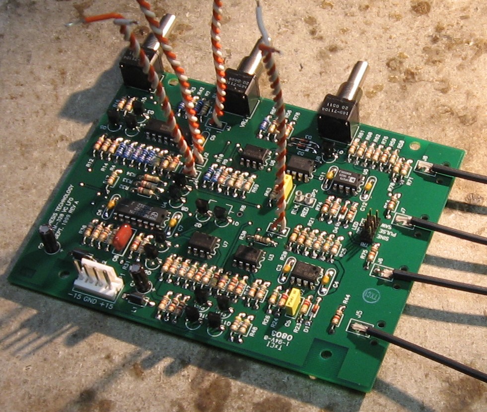
We got hold of several MUUBs when we were planning our module construction, This is what the MUUB4 looks like front and back (click here for more detail)
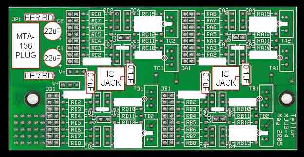
You can see it's got space for a lot of stuff on there - places for components typically found in synth circuits. Like up in the upper left corner - there's where the power connections happens - and it looks like those places on all the modules' PCBs... the place for the plug, the ferrite beads, those (usually) blue capacitors. And you can see where two ICs would go. These things are pretty obvious. Scott has instructions on how to build the DB on his site in the MUUB User's Guide. Click here for the page on his site. Click here for the user's guide. We had no idea what we were doing, but we figured it out. If you want to read about our tedious process, you can skip to the bottom of the page where we've documented it - mostly to encourage those-who-come-after and are also idiots. But you needn't bother, just read on. |
|||||||||||||||||||||||||||
|
MOTM 320 Motherboard Modifications |
|||||||||||||||||||||||||||
|
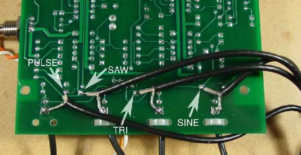
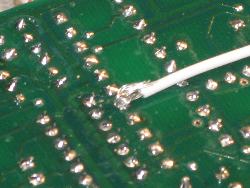
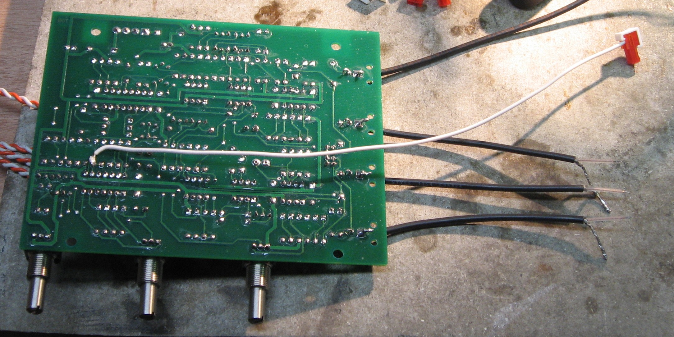
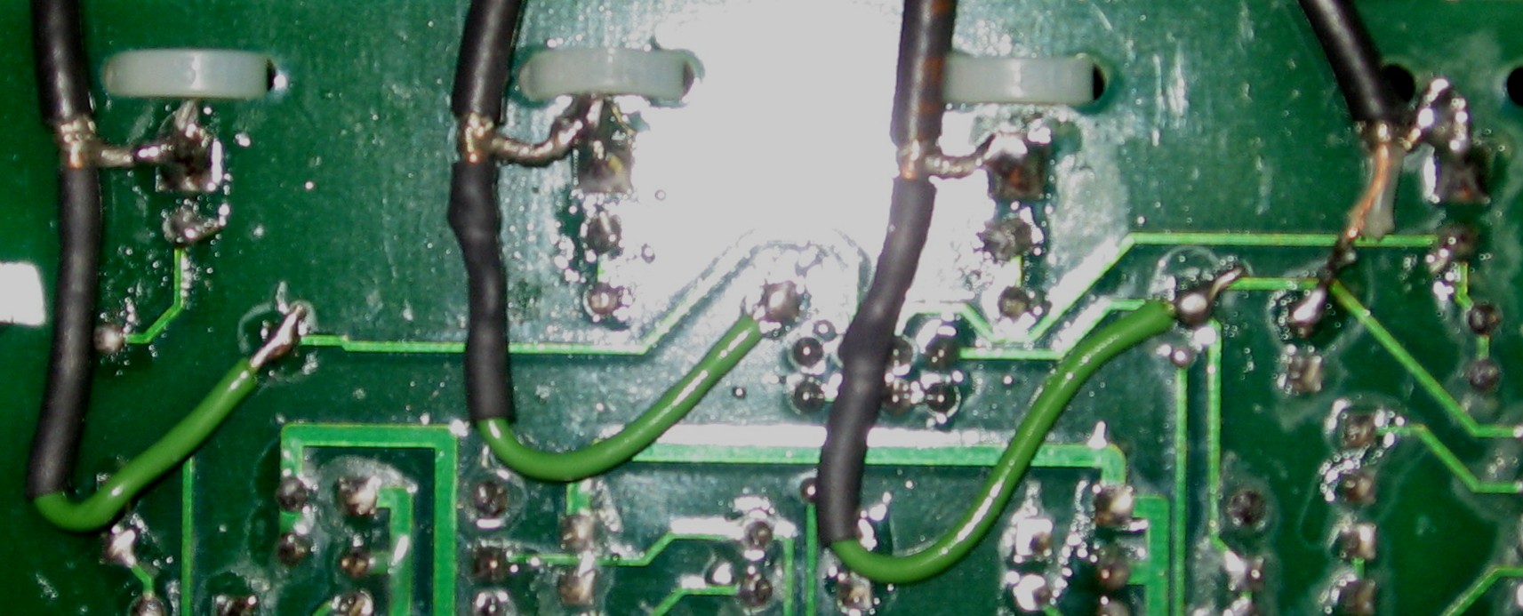
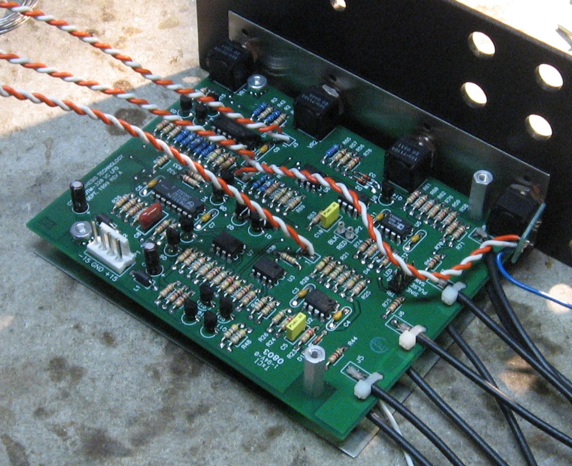
The installation of the 320DB requires modifications during (or after) the construction of the MOTM 320. Let's take a look at those modifications before we begin to build the 320. A. Feeding the waveforms to the 320DB from the 320 This will be done with coax cable from the underside of the 320 motherboard. Scott shows it like this:
Scott Juskiw We've re-calculated the cable lengths given our use of the MUUB4 like this:
At the other end of those feeds, there will be 2pin MTA plugs. We asked Scott Juskiw if there would be an advantage to soldering in the shield as well as the signal lead into those plugs. Here's what he said: "Hi Bill and Will, the original 320R daughterboard didn't have any place to connect the grounds for the four LFO outputs from the MOTM-320. I could have used an 8-pin connector, or four 2-pin connectors, but those ground connections would have been redundant. The four coax cables are connected to ground on the MOTM-320 so that they are still shielded connections. All that matters, electrically, is that the shield is connected to ground at one end. With a MUUB-4 implementation I would probably hook up the shield at both ends, just to ensure that at least one end is connected to ground should a wire become accidentally disconnected over time. Also, the shield is a lot thicker than the centre wire, so having it connected at both ends provides a stronger mechanical connection." OK - sounds good to us. B. Connecting the RANGE switch The range switch, per our implementation, is connected to the MUUB4, but to make it work, it also requires a connection between the MUUB4 and the 320 motherboard. That connection to the 320 motherboard will be like Scott's illustration here, except without the resistor in line (we put that on the MUUB4 as you'll remember) - so the wire will attach where Scott shows the resistor soldered on:
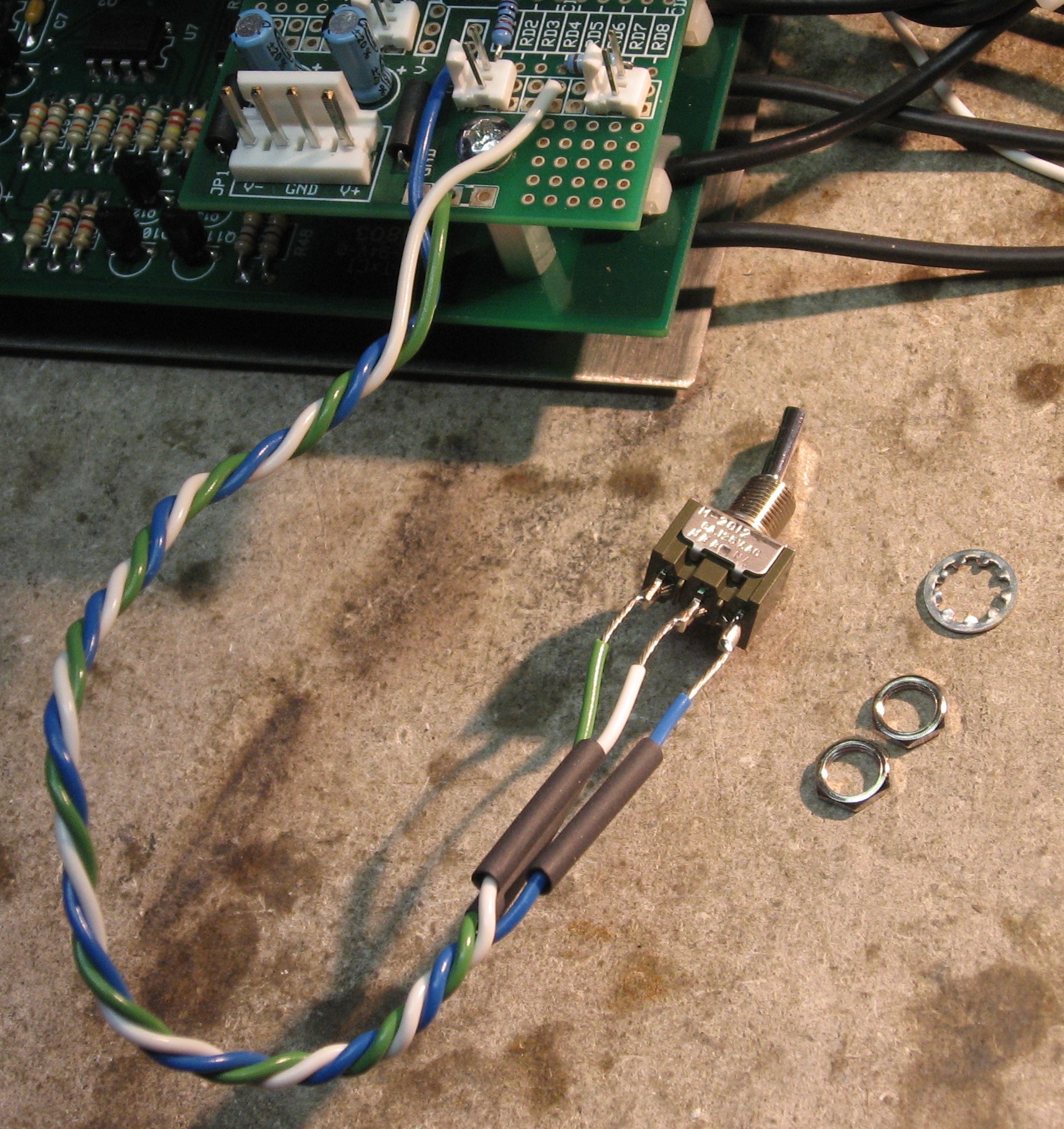
Scott Juskiw That wire, we calculate it should probably be 7 inches long, will go to the right pin on the 2-pin MTA header we put at "JD1-RD7." Then the Range Switch will connect to the MUUB4 via the three wires - on our MUUB4 we used white, green, and blue Scott shows the switch connection like this:
Scott Juskiw And here's how they relate to our MUUB4:
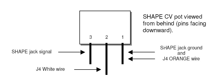
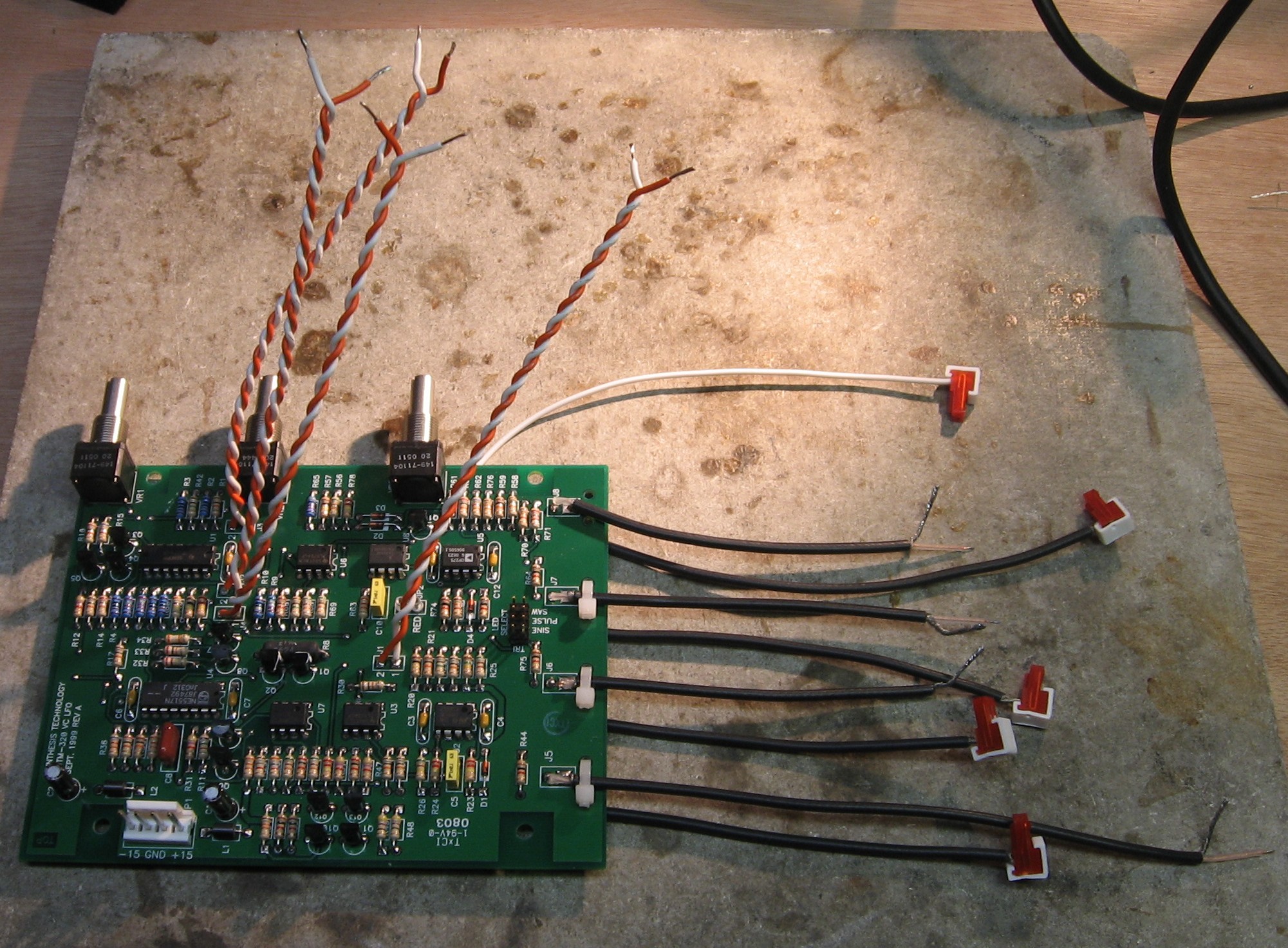
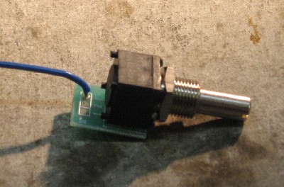
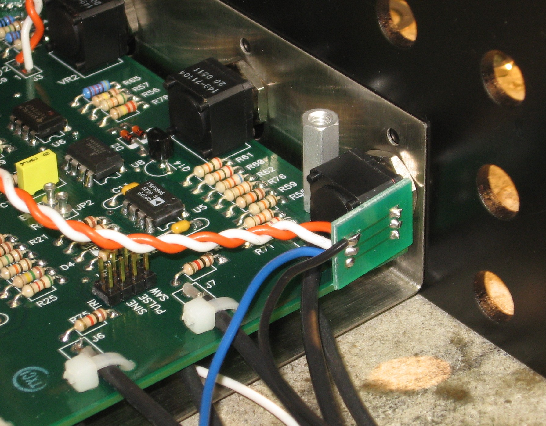
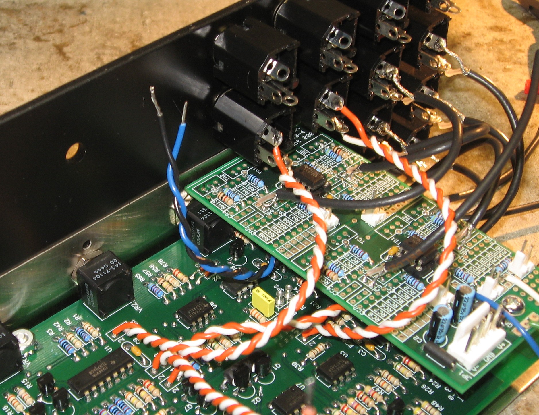
C. Installing the SHAPE CV pot (including omission of J8 cable tie) As Scott explains: "On a 'stock' MOTM-320, the SHAPE Jack is connected directly to 'J4' on the motherboard via a twisted pair of wires (white and orange)." The modified 320 has a "SHAPE CV" pot inserted between the SHAPE jack and J4. So when it comes time for that connection, we have to remember to make them like this:
Scott Juskiw So those orange and white wires coming from J4 on the 320 motherboard get soldered instead to pins 1 and 2 of the SHAPE CV pot respectively. Then the SHAPE jack gets connected to the pot - jack tip contact to pin 3 on the pot, jack shank contact to pin 1 - using a 6" twisted pair of wires. According to Scott, when building the 320, the cable tie at J8 must be omitted in order to get the SHAPE CV pot in place. D. Power Connector Scott recommends using a pass-through MTA connector to provide the power connection to the motherboard and the MUUB4. |
|||||||||||||||||||||||||||
Parts |
|||||||||||||||||||||||||||
|
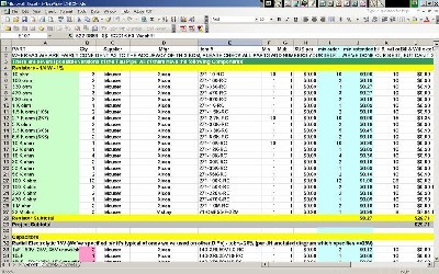
In 2008 (or thereabouts), Synthesis Technology stopped producing full-blown kits, and moved toward what Paul calls "2.0" (two-dot-oh) DIY. This assumes the builder will buy certain parts from Synthesis Technology - PCB, Panel, and in some cases a Special Parts Kit of the particularly hard to find parts - and will get the rest of the parts from Mouser or Digikey or - well - wherever. For those who are building this as a "two-dot-oh" project, Will and I, with feedback and review from others, have developed a parts-list / bill-of-materials in the form of an XL spreadsheet (as usual). Please don't take it as gospel. We've been over and over it and are relatively confident in our specifications - and we hear that several people have used it successfully so you should be good. The BOM assumes that you get the "extra parts kit" from Synthesis Tech. Synthesis Technology offers some parts like pots and knobs at particularly good prices... these options are offered in the BOM. Please note that this BOM does not include the parts for the Tellun Daughter-board addition.
Click here to download our XL spreadsheet Parts List But we put together this BOM which does include the parts for the Tellun Daughter-board addition. Those parts are detailed in Scott Juskiw's "User Manual" on his site as well. Please heed the previous forewarning regarding its accuracy, blah blah blah. We do our best, but we're far from perfect. Click here to download our XL spreadsheet Parts List |
|||||||||||||||||||||||||||
Panel |
|||||||||||||||||||||||||||
|
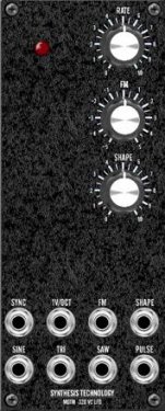
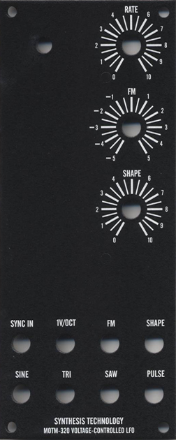
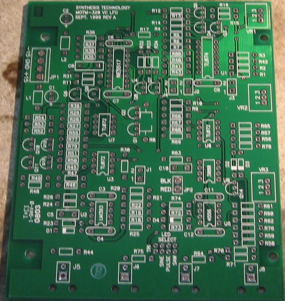
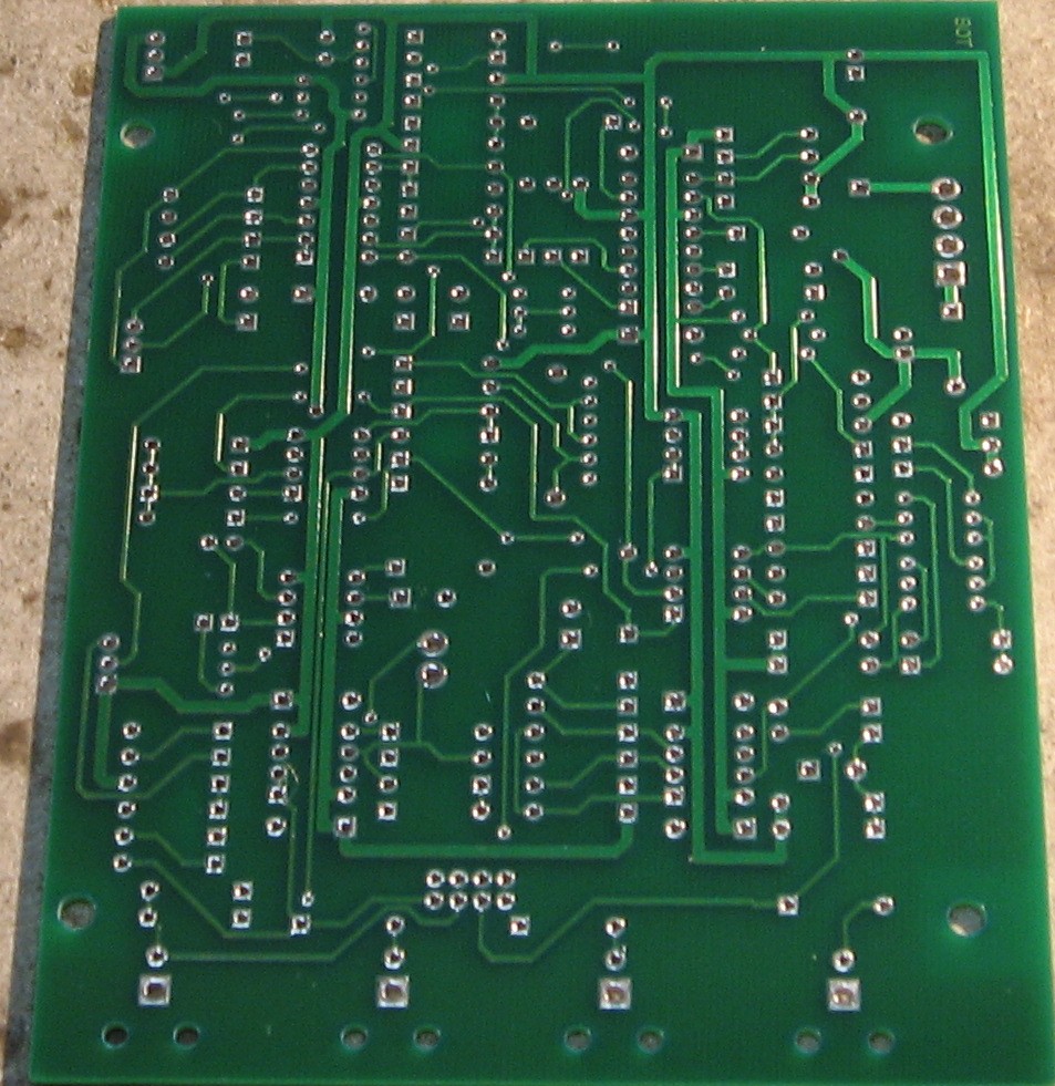
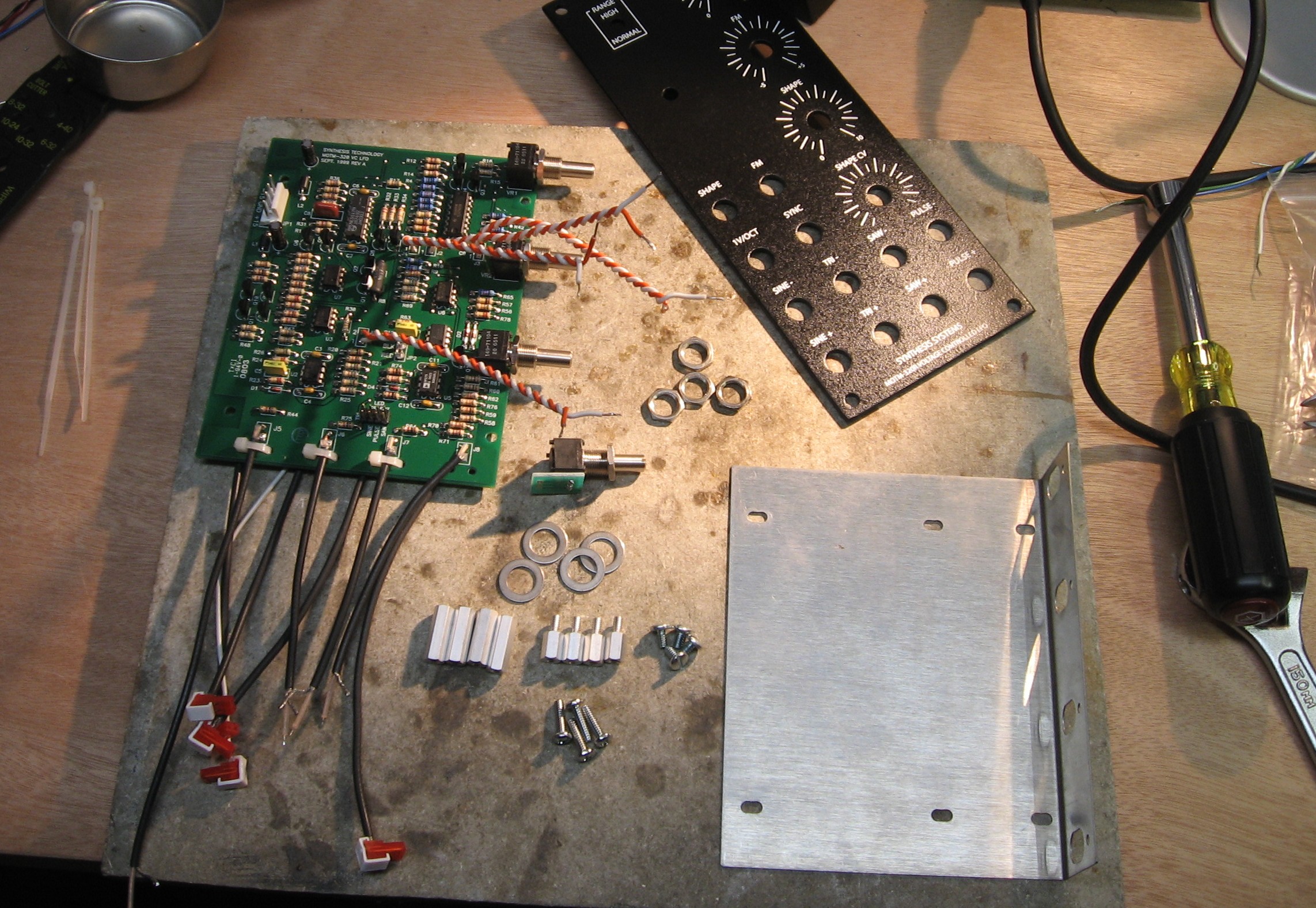
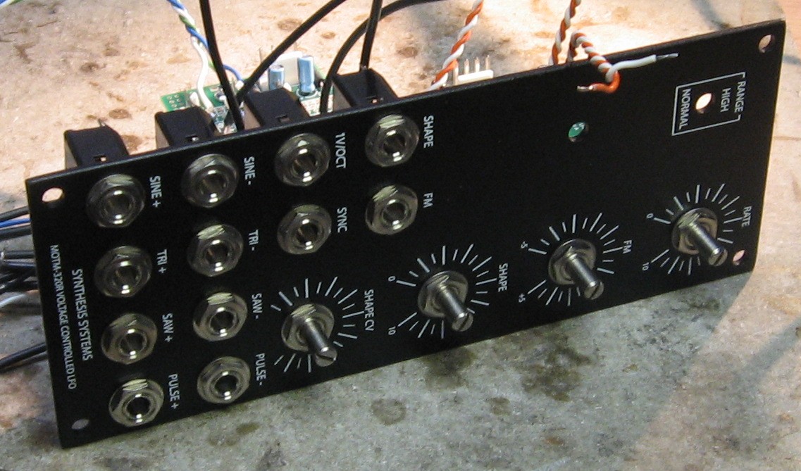
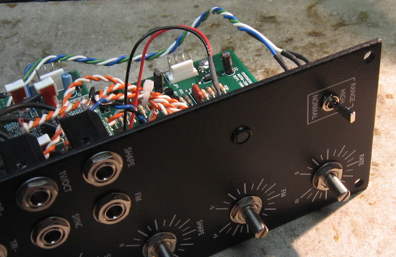
If you're a 2.0 DIY builder you'll get your panel from Synth Tech and here's what it'll look like:
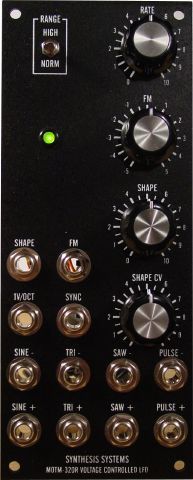
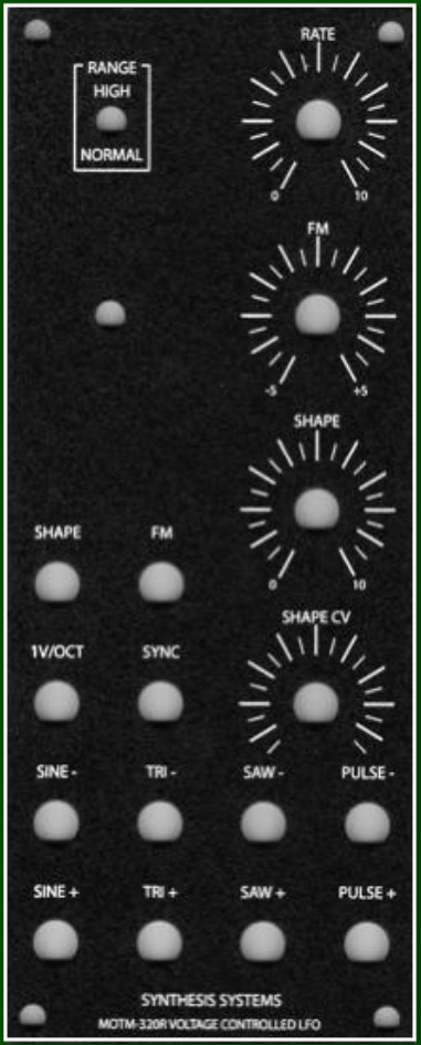
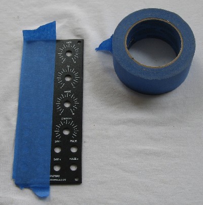
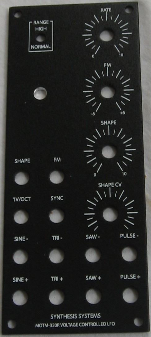
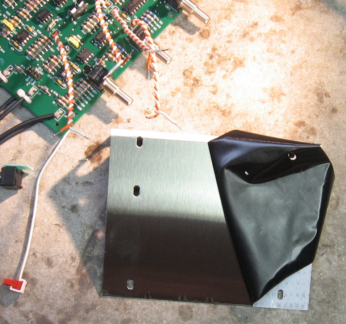
But if you're doing a 320R build, we got our 320R panel from Bridechamber:
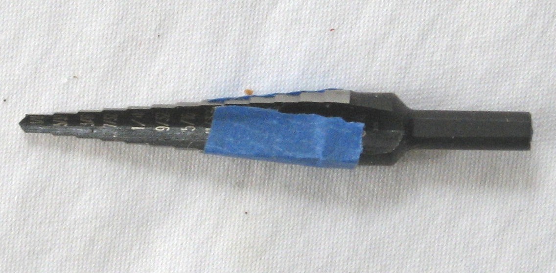
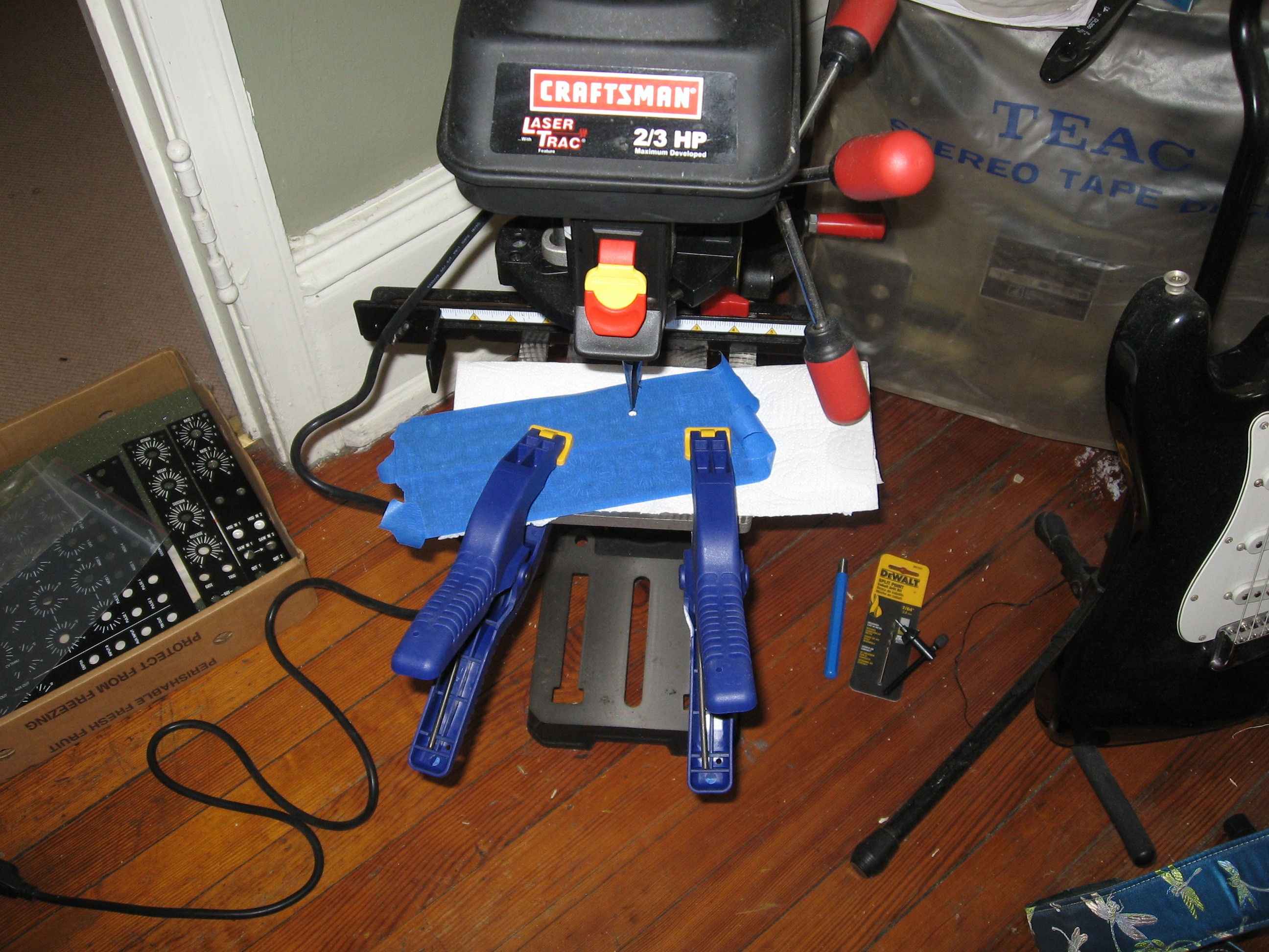
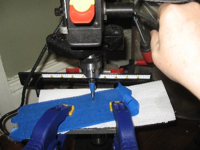
The Bridechamber panel comes with a 1/4" LED hole - so we need to drill it out to the 5/16" size for the LED that came in our 320 kit:
|
|||||||||||||||||||||||||||
320DB - MUUB 4 Construction |
|||||||||||||||||||||||||||
|
Jumpers |
|||||||||||||||||||||||||||
|
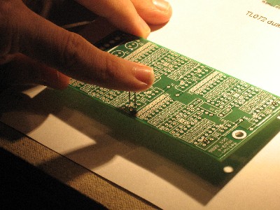
Here's where the jumpers go:
Will solders them in:
After a hiatus, Jan 2008 - |
|||||||||||||||||||||||||||
|
Resistors |
|||||||||||||||||||||||||||
|
|
|||||||||||||||||||||||||||
|
Caps, IC jacks, Axial Ferrite Beads, Power Header |
|||||||||||||||||||||||||||
|
|
|||||||||||||||||||||||||||
|
Waveform connection MTA headers |
|||||||||||||||||||||||||||
|
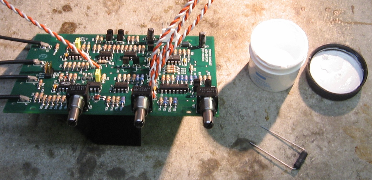
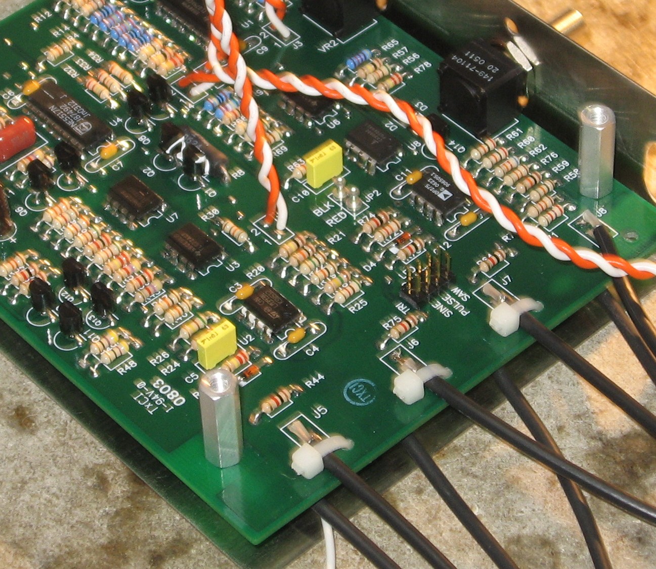
The original DB320 had a nice 4-pin MTA header for the 320DB ends of the "waveform" co-ax cables, but the MUUB4 doesn't. Instead, you can solder directly or install 4 separate 2-pin headers (that's what we're going to do). These go at JA1 (TRI), JB1 (SAW), JC1 (SIN), and JD1 (PULSE):
There is, no doubt, a standard for this kind of thing, and, if so, we've got a 50-50 chance of installing the headers according to the standard. But looking at the board, we think it might be easier to manage the connections if the headers are installed so their left pin is ground - this puts the lock on the top per the above image. |
|||||||||||||||||||||||||||
|
Inverted outputs |
|||||||||||||||||||||||||||
|
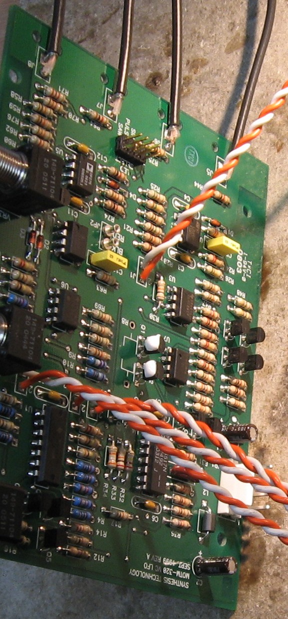
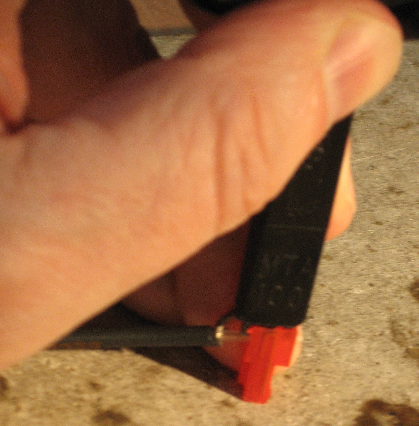
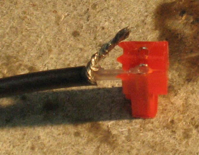
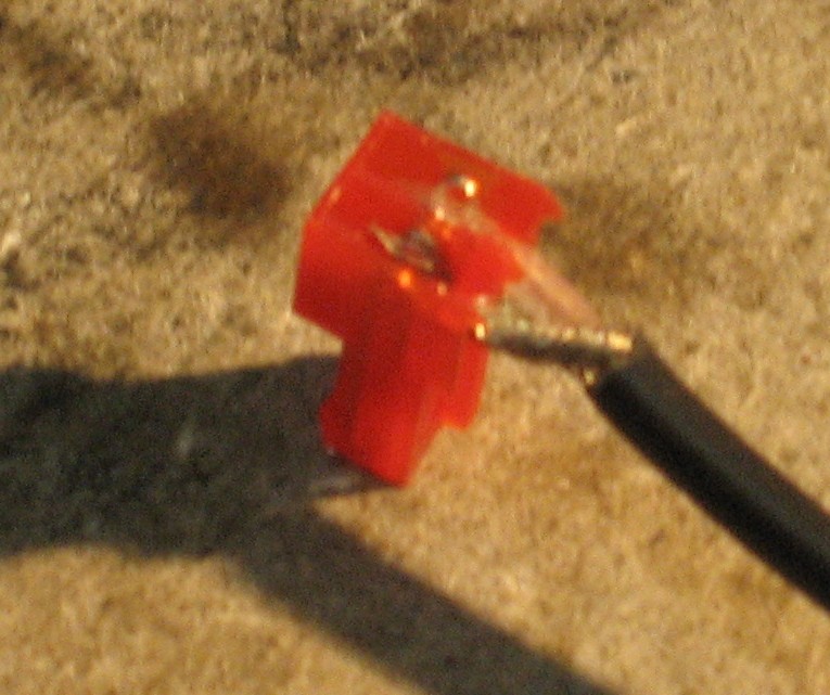
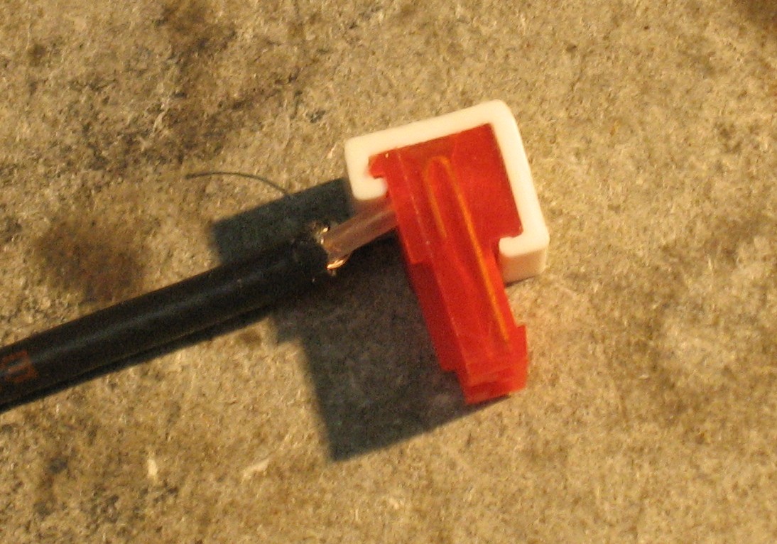
The original DB320 had nice MOTM-pcb-style pads and tie-down-holes for the coax-to-inverted-output jacks, but the MUUB4 doesn't. Instead, we'll solder directly at JA9 (TRI-), JB9 (SAW-), JC9 (SINE-), and JD9 (PULSE-). In Scott's original DB120 user's guide, he recommends using 4" pieces of co-ax. We bet this will still hold true, but we're going to use 4-1/2" pieces just in case. Click here for a detailed description of stripping and tinning coax.
|
|||||||||||||||||||||||||||
|
Range Switch Connection |
|||||||||||||||||||||||||||
|
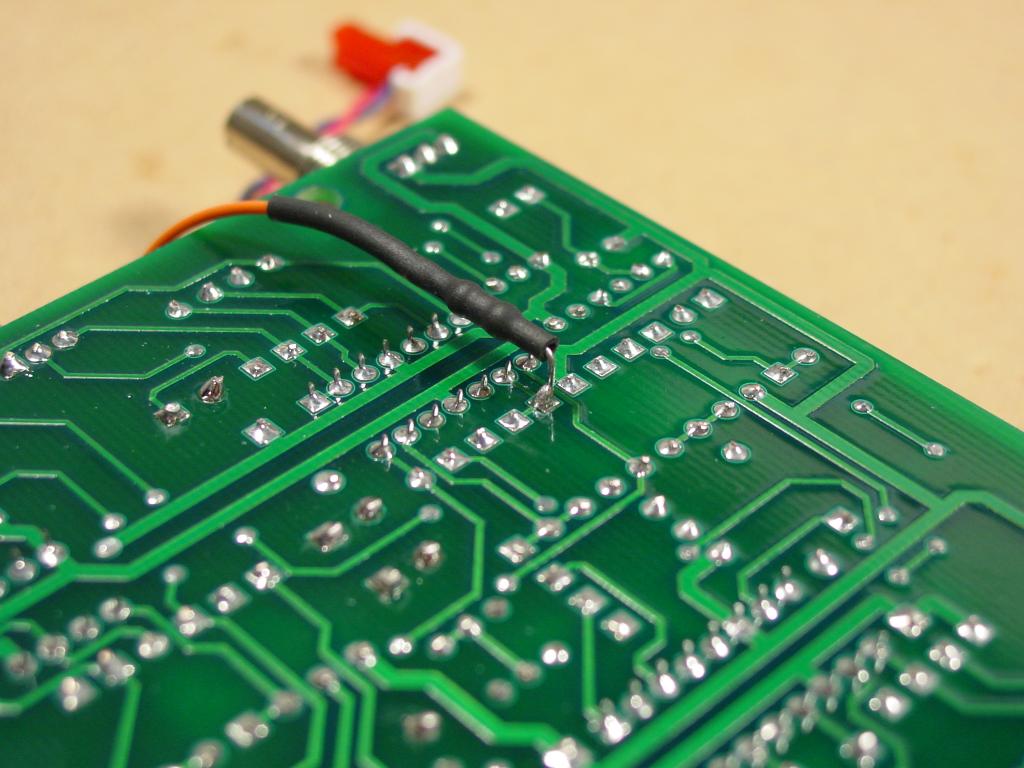
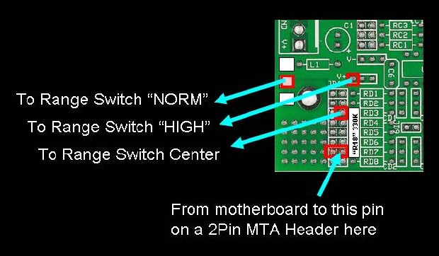
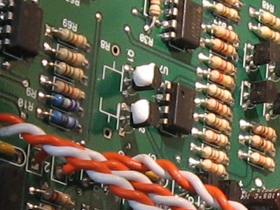
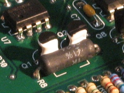
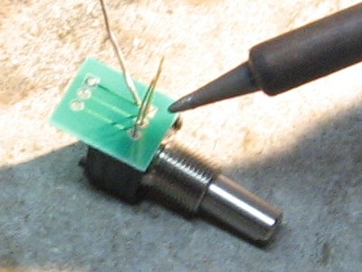
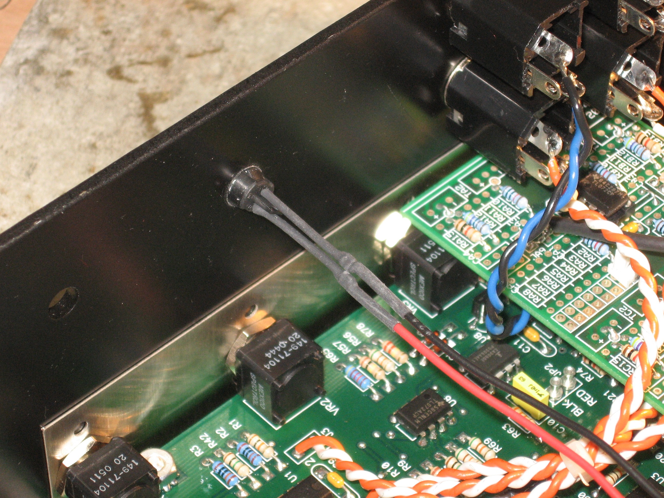
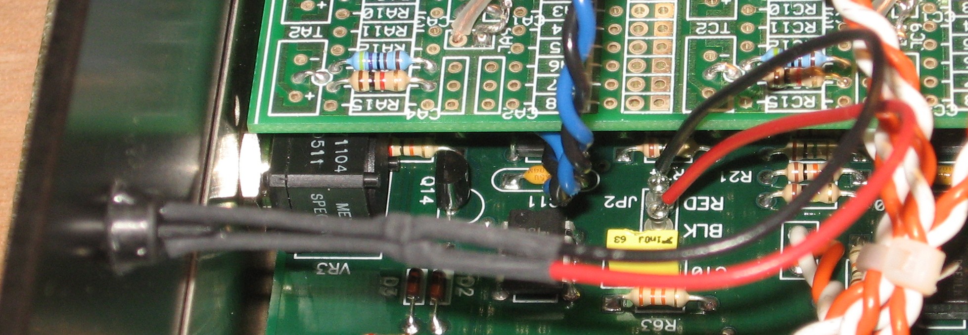
The original DB320 had a nice 2-pin MTA header to connect the range switch (norm) to ground and (high) to +15V. The center position of the switch is connected to the underside of the 320 motherboard via a resistor (he calls "R18"). In Scott's implementation, that resistor is soldered to the U1-pin-9 end of R7 (not directly to U1-pin-9):
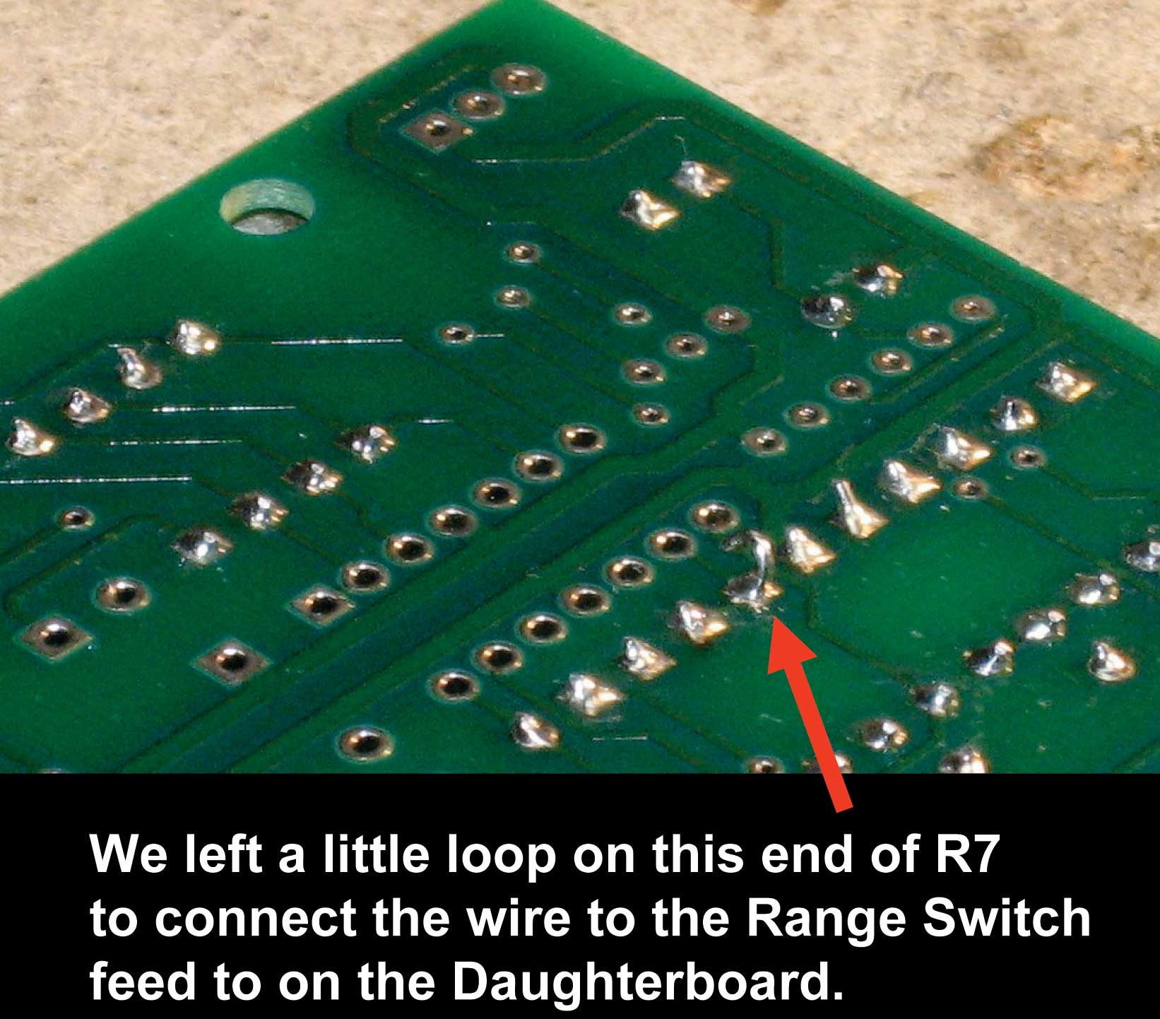
the resistor is under the shrink-tubing (see the bumps?) and soldered directly to R7 on the U1 end. We propose doing it like this instead:
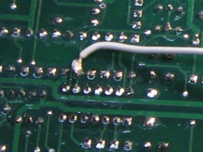
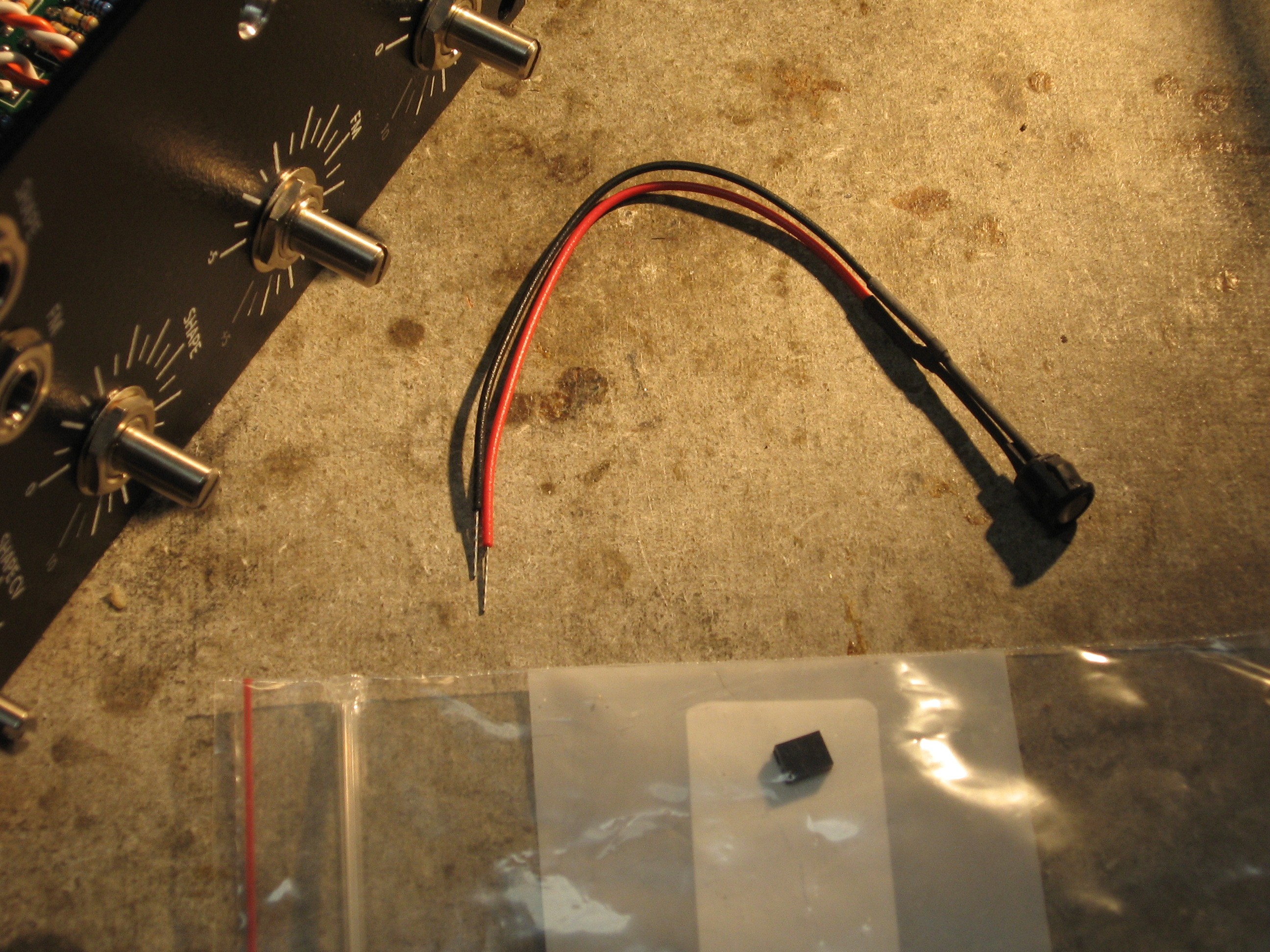
We'll put the "R18" 330K on the MUUB4. We'll provide an MTA-2 header to connect the lead from the 320 motherboard (U1-pin-9 end of R7) to "R18." Then we'll solder in three 9" lengths of wire that go to the switch. Later, on the bottom of the 320 motherboard, we'll just solder a wire to that R7 and a MTA plug on the other end.
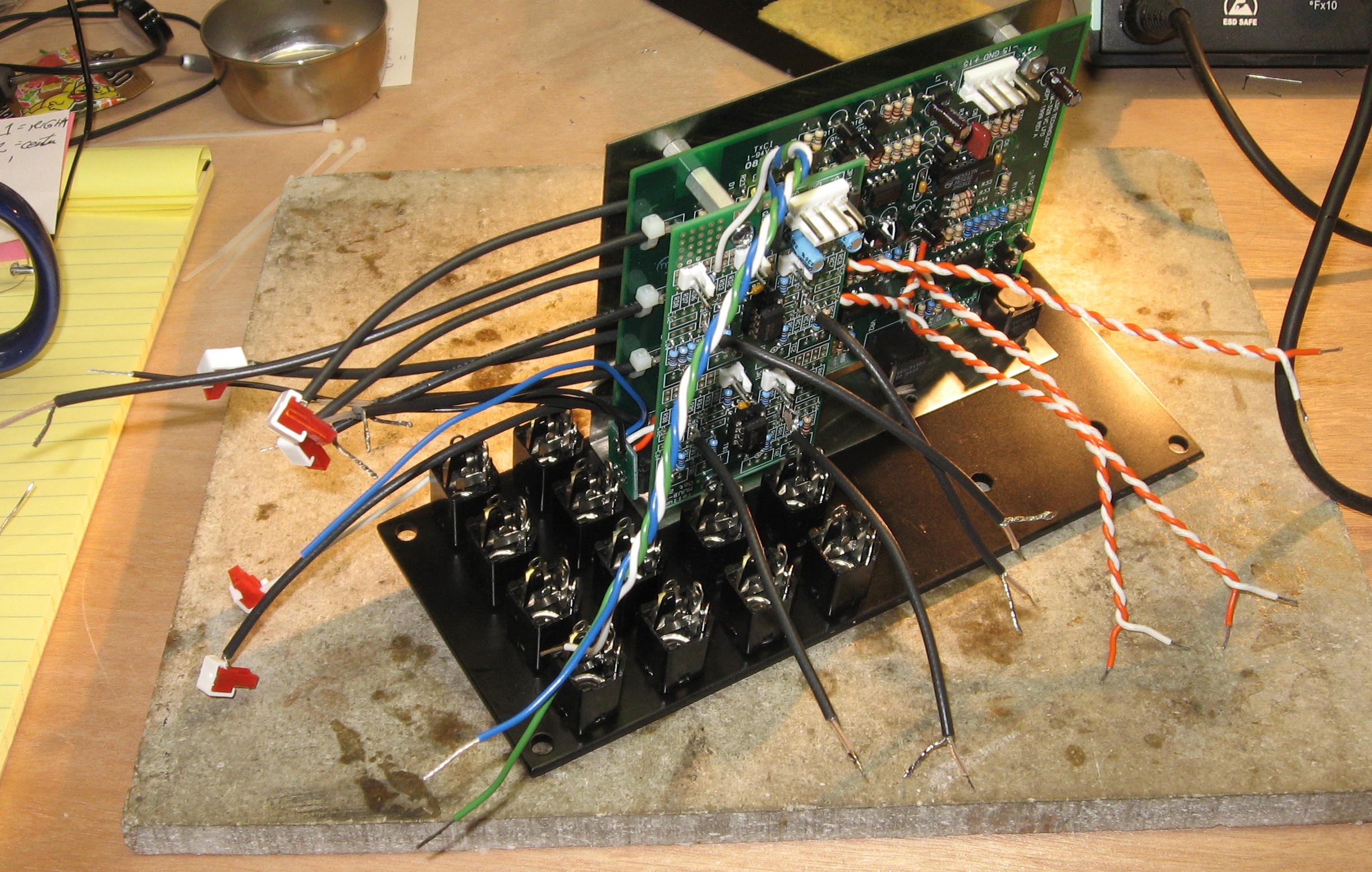
the finished daughter board |
|||||||||||||||||||||||||||
Construction Phase 1All the stuff in Phase 1 gets soldered using "Organic" Solder. At every break in the action, we wash the board off to get rid of the flux. |
|||||||||||||||||||||||||||
|
|
|||||||||||||||||||||||||||
|
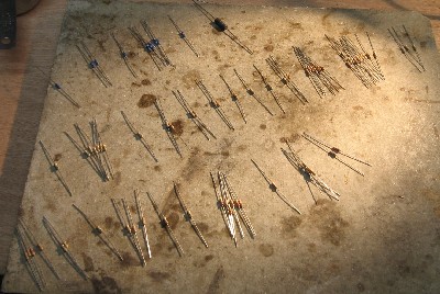
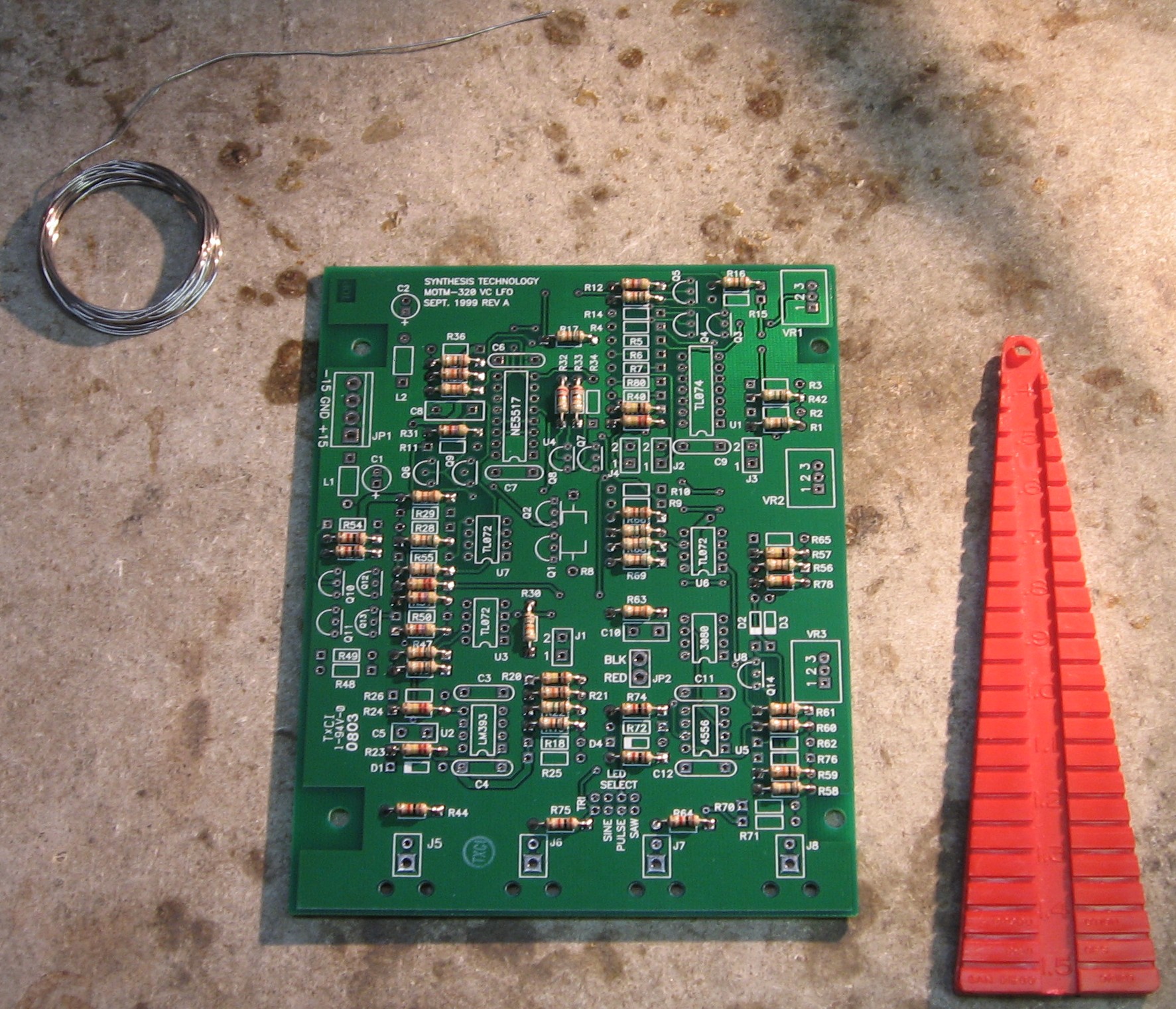
Resistors |
|||||||||||||||||||||||||||
|
Part 1
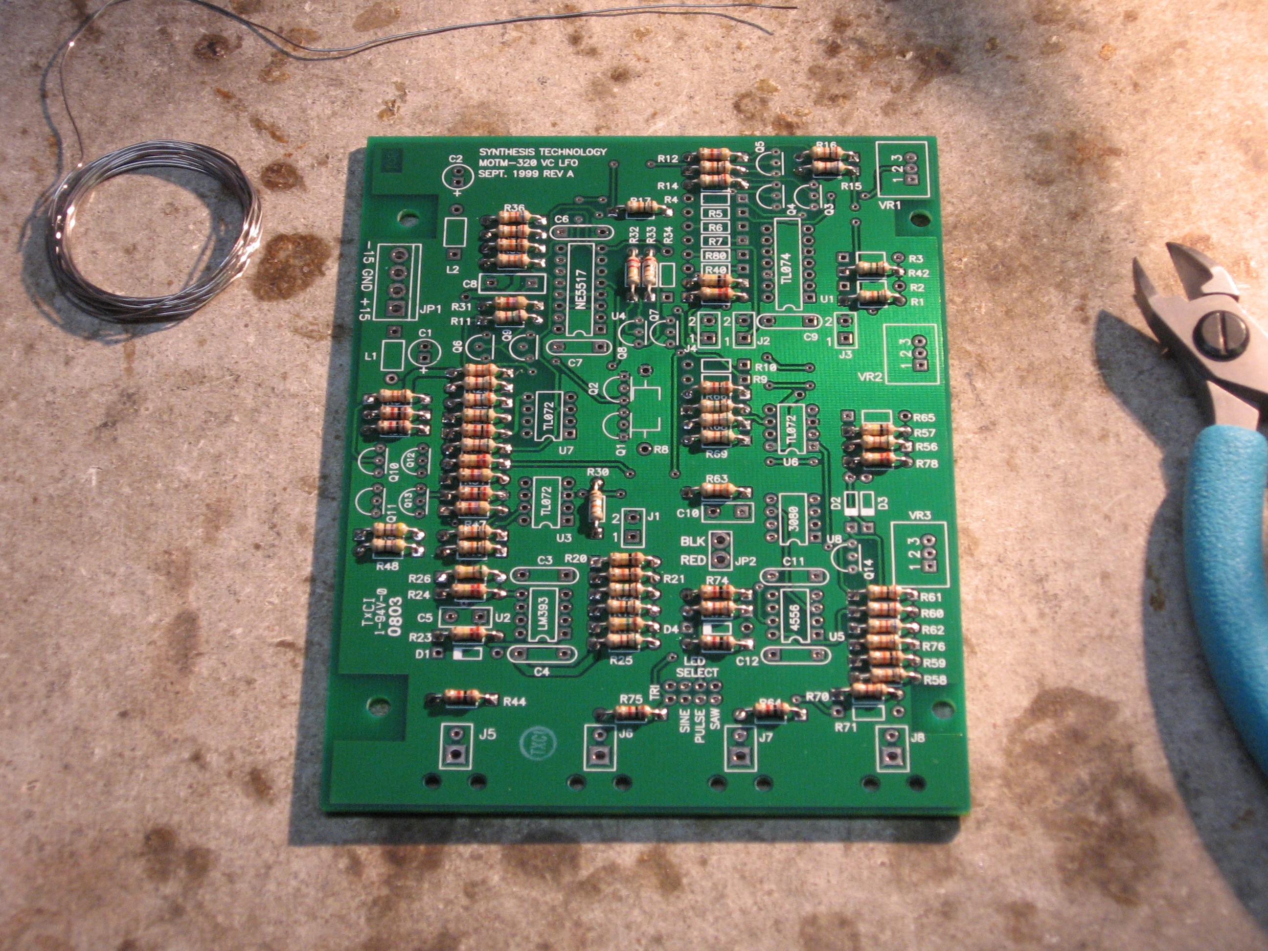
Part 2
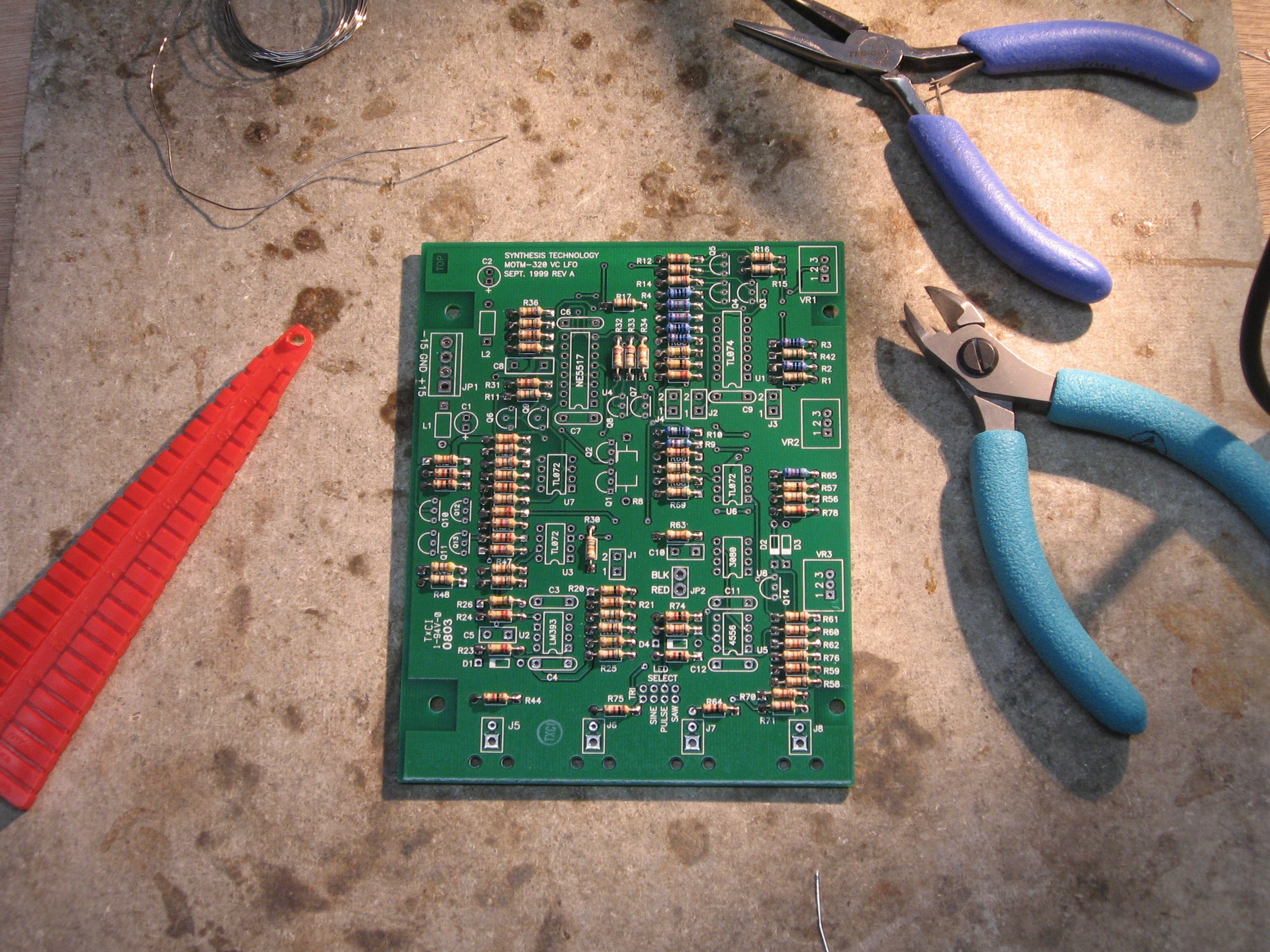
Part 3
Range Switch hook-up
|
|||||||||||||||||||||||||||
|
Capacitors |
|||||||||||||||||||||||||||
|
|
|||||||||||||||||||||||||||
|
ICs etc... |
|||||||||||||||||||||||||||
|
|
|||||||||||||||||||||||||||
|
|
|||||||||||||||||||||||||||
Construction Phase 2All the stuff in Phase 2 gets soldered using "No-Clean" Solder and the PCB doesn't get washed off from here on. |
|||||||||||||||||||||||||||
|
Coax and the rest of it... |
|||||||||||||||||||||||||||
|
|
|||||||||||||||||||||||||||
|
Mods for Daughter Board |
|||||||||||||||||||||||||||
|
The Shape CV pot -
Range switch connection wire -
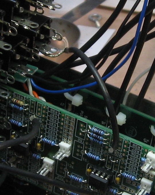
Coax connections -
|
|||||||||||||||||||||||||||
|
Stooge Bracket |
|||||||||||||||||||||||||||
|
|
|||||||||||||||||||||||||||
|
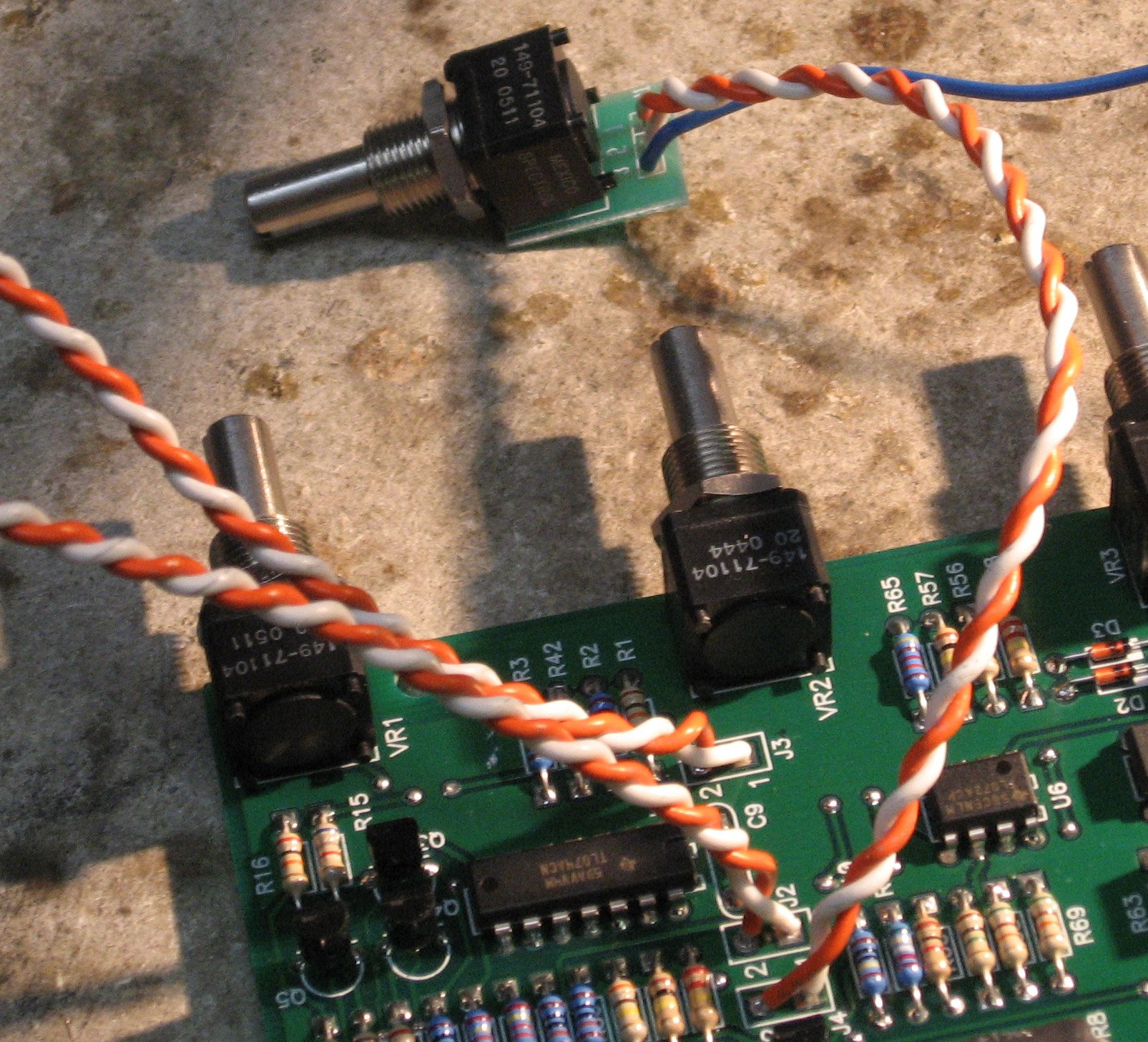
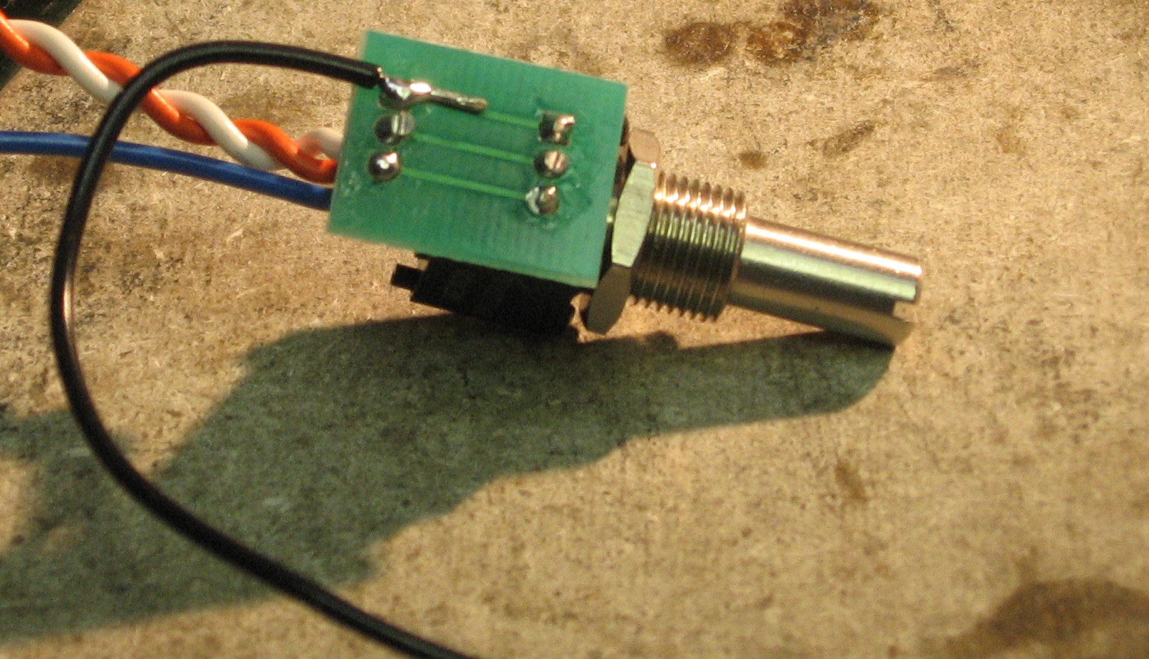
The Shape CV Pot connections |
|||||||||||||||||||||||||||
|
|
|||||||||||||||||||||||||||
|
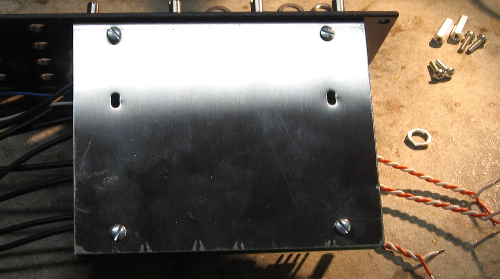
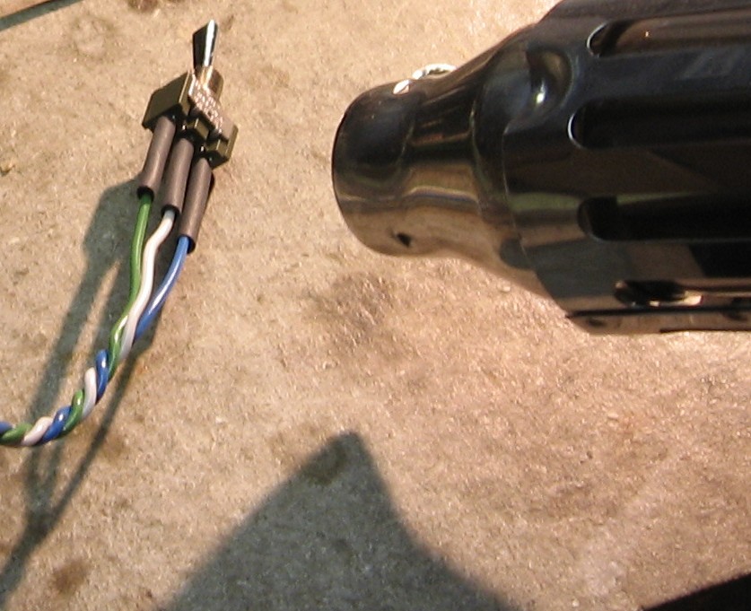
Stooge bracket mounts to panel |
|||||||||||||||||||||||||||
|
|
|||||||||||||||||||||||||||
|
Mounting the Daughter Board |
|||||||||||||||||||||||||||
|
|
|||||||||||||||||||||||||||
|
The Jacks |
|||||||||||||||||||||||||||
|
|
|||||||||||||||||||||||||||
|
The LED and Jumper |
|||||||||||||||||||||||||||
|
Now for the jumper that controls what the LED displays
|
|||||||||||||||||||||||||||
|
Range Switch |
|||||||||||||||||||||||||||
|
|
|||||||||||||||||||||||||||
|
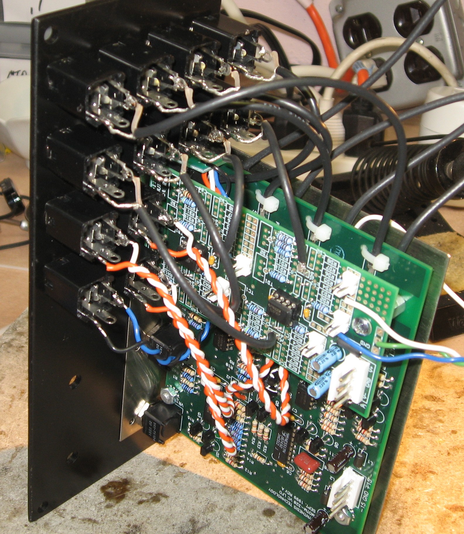
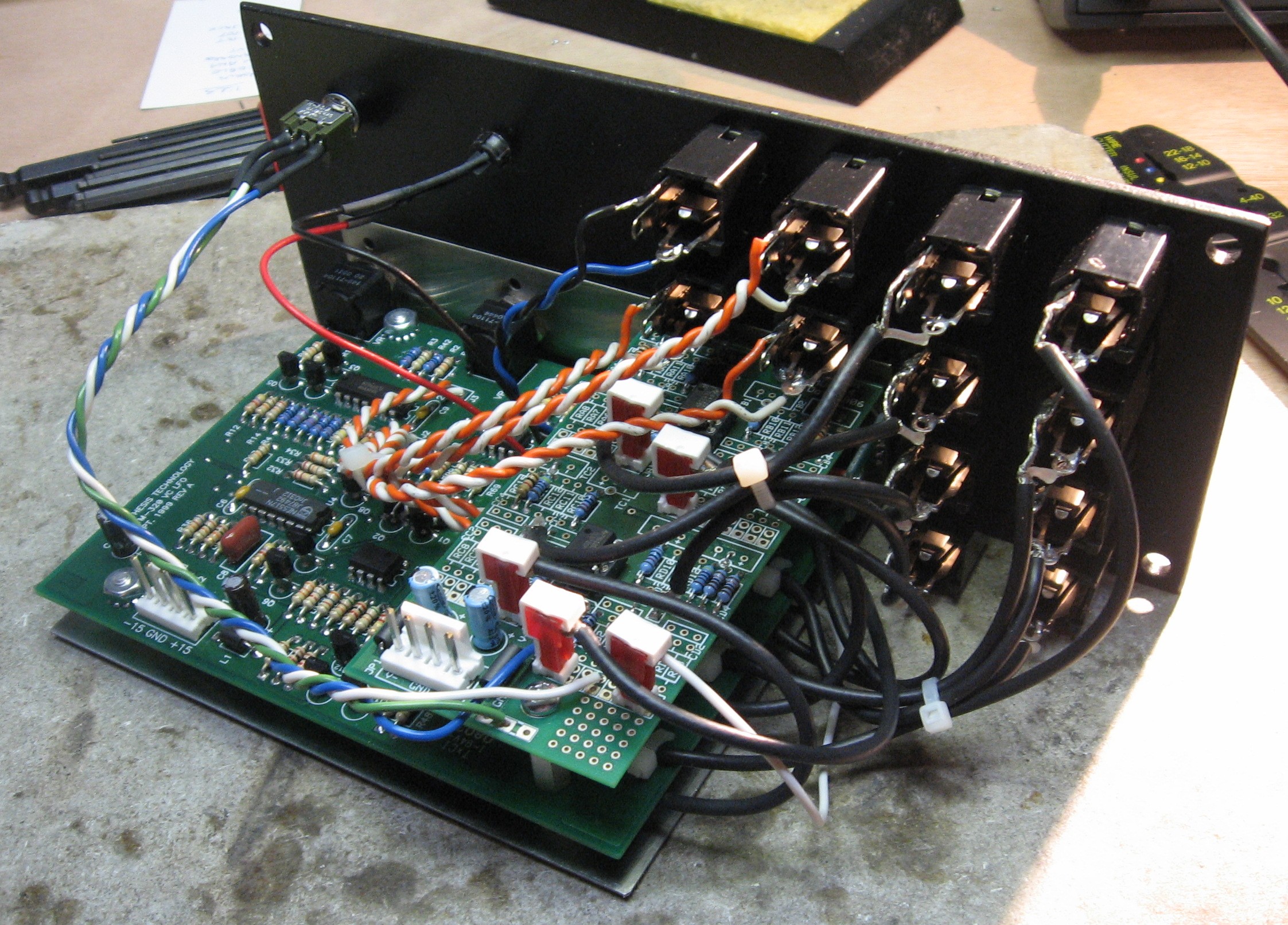
Construction done! |
|||||||||||||||||||||||||||
|
|
|||||||||||||||||||||||||||
Set up / Testing |
|||||||||||||||||||||||||||
Use Notes |
|||||||||||||||||||||||||||
Our Tedious Floundering About
|
|||||||||||||||||||||||||||
|
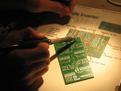
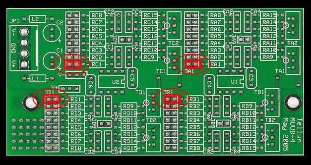
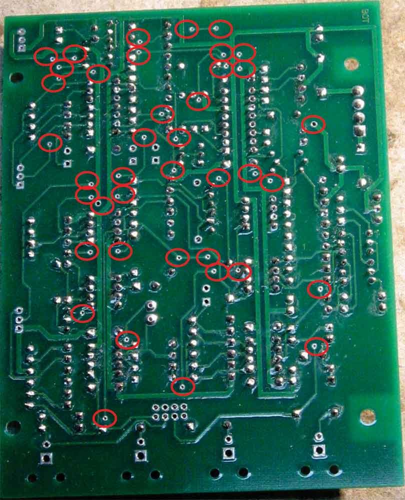
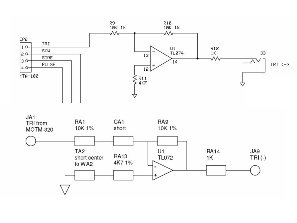
We went through the following process in the course of figuring out how to build the circuits and how to document them here. And We're including it here so you can too if you want to. So - remember - we're complete idiots... well - again, not Will - he's 15. But his old man certainly is - and so we were confused about exactly what Scott's instructions meant. There are four circuits involved - a circuit that inverts the triangle wave output (we're calling that the Triangle Inverter), and others that invert the Saw, the Sine, and the Pulse outputs. We could see that the four circuits are very similar - so to figure out Scott's instructions, we took the Triangle Inverter and studied it. Scott's diagram shows components being soldered into the MUUB4 but in each inverter, he indicates two "shorts." We were a little confused about exactly where the "shorts" or jumpers should be. So we took a close look at the schematics, and cross referenced them with Scott's instructions and with MUUB4 PCB. Here is the schematic drawing for the Triangle inverter and the diagram Scott made up for the MUUB4.
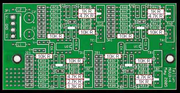
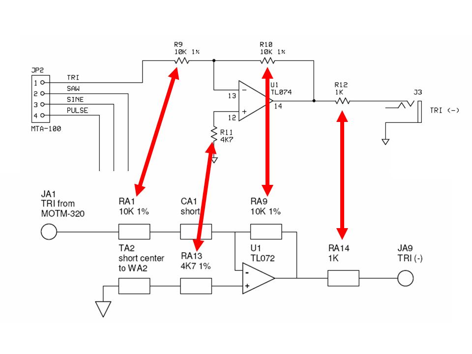
We figured: "We know what resistors look like," so we focused in on them first.
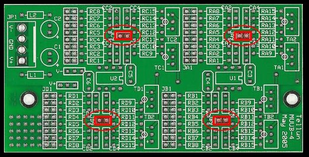
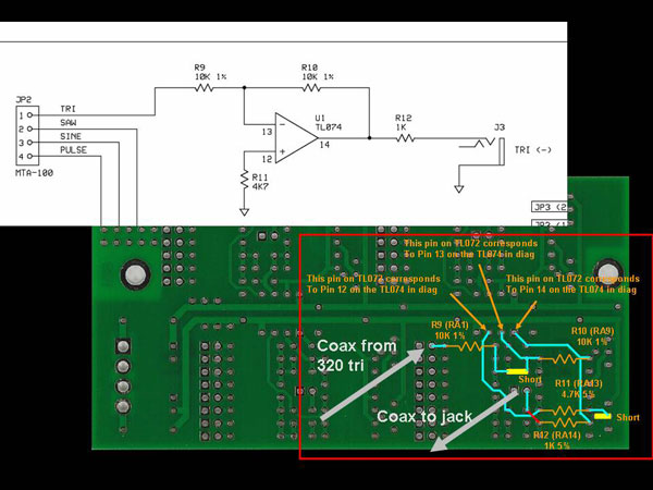
That helped us get our bearings. OK - so some things are clearly labeled on the MUUB - RA1, RA9, RA13, RA14, U1. But the "CA1 short" - hmmm - the "CA1" label is hard to see on the board and although we found it, we weren't really sure what it corresponded to. So we looked at the back of the MUUB4 and began to work out exactly where the jumpers should go by following the traces. In this way we tried to figure out where Scott meant us to put the CA1 jumper. He really meant us to jump from the top to the bottom hole of CA1... but we didn't even know enough to figure that out. But because we were following the traces, the way we figured to do it, by jumping top hole of CA1 to the top hole of CA2 worked too. Following the traces again, we got stuck at the end where Scott says to put a jumper from the middle of TA2 to ground at WA2. We didn't know what WA2 is - So we asked Richard Brewster for help. And he told us where to put the jumper. Here's a diagram to show how we followed the traces:
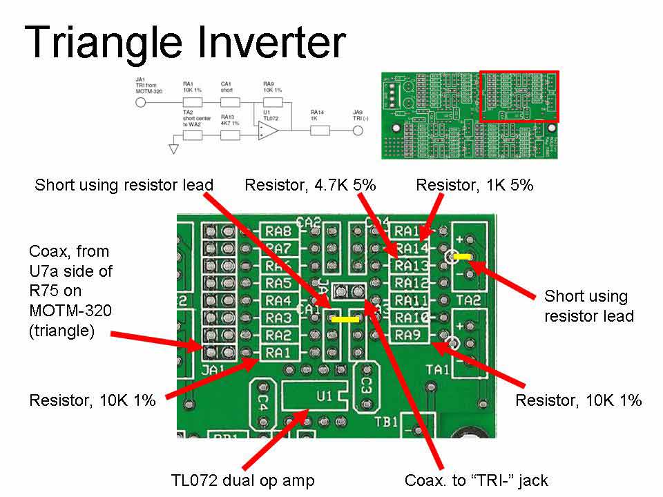
And this diagram shows where the parts should go for the Triangle Inverter. Although Scott's schematic shows a TL074 op amp (the TL074 IC has 4 amps in it), The MUUB uses two TL072s instead (each TL072 has two op amps). This image is really larger than it looks on the web page. If you right-click on it and then select "View Image," you can see it in more detail. The other three inverters are very similar.
|
|||||||||||||||||||||||||||
|
|


|
The fine Print: Use this site at your own risk. We are self-proclaimed idiots and any use of this site and any materials presented herein should be taken with a grain of Kosher salt. If the info is useful - more's the better. Bill and Will © 2005-2011 all frilling rights reserved
|