Bill and Will's Synth
|
||
Table of Contents |
||
|
This page has become really long, so here's a table of contents that we hope will make it easier to traverse: Background - presents an explanation and Paul Schrieber's initial description of the Module with a couple photos from Larry Hendrey Modifications - presents details of Larry Hendry's Fine Tune Modification and Paul Haneburg's Tracking Adustment Parts - presents a Bill of Materials for "two-dot-oh" builders and notes about it Panel - presents the MOTM format panel Construction Phase 1 - Resistors, Capacitors, IC Sockets, Power Plugs, MTA headers Construction Phase 2 - Trimmers, Panel connections |
||
Background |
||
|
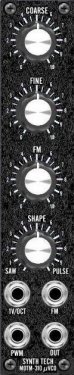
Paul Writes: "The MOTM-310 is perfect for adding additional VCOs to your system. Using the same "core" circuitry as the MOTM-300 UltraVCO, the MOTM-310 retains its superior stability and sonic characteristics in half of the space. Great for driving the SYNC of MOTM-300's, and for building portable systems.
|
||
Modifications |
||
1. Fine Tune Mod. |
||
|
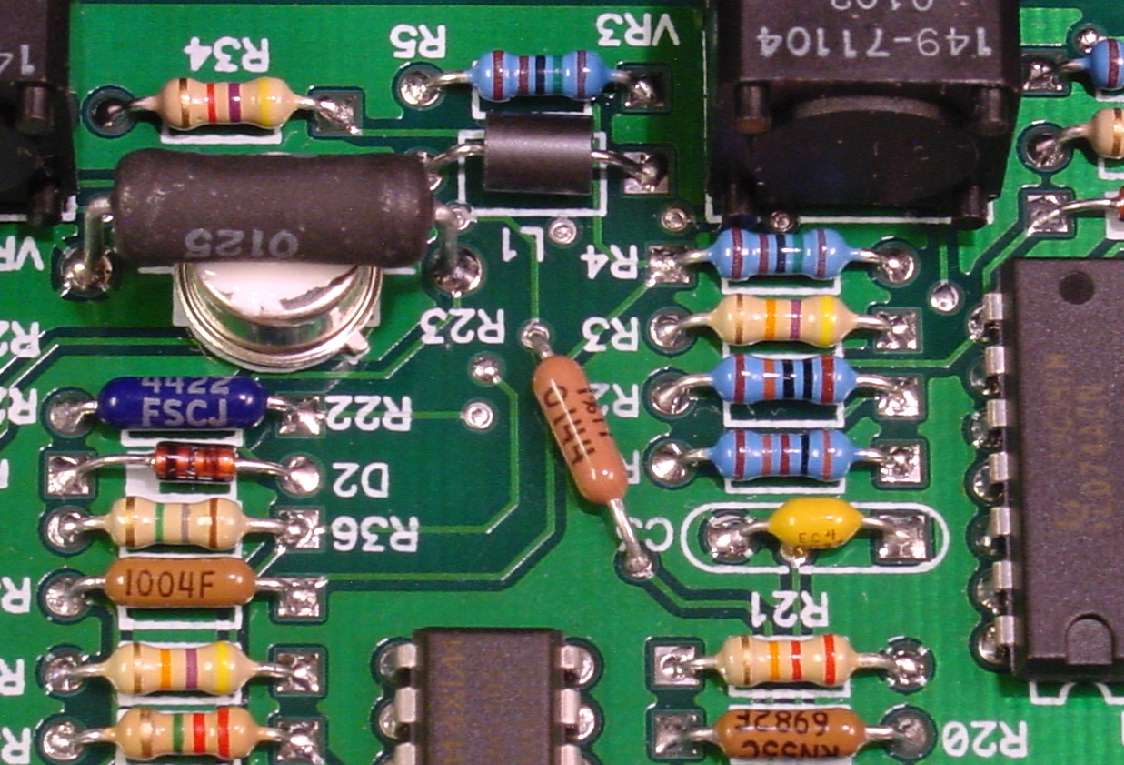
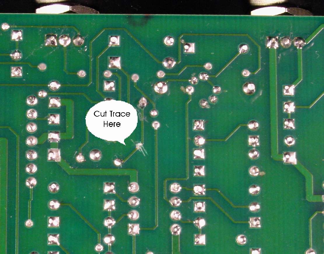
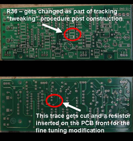
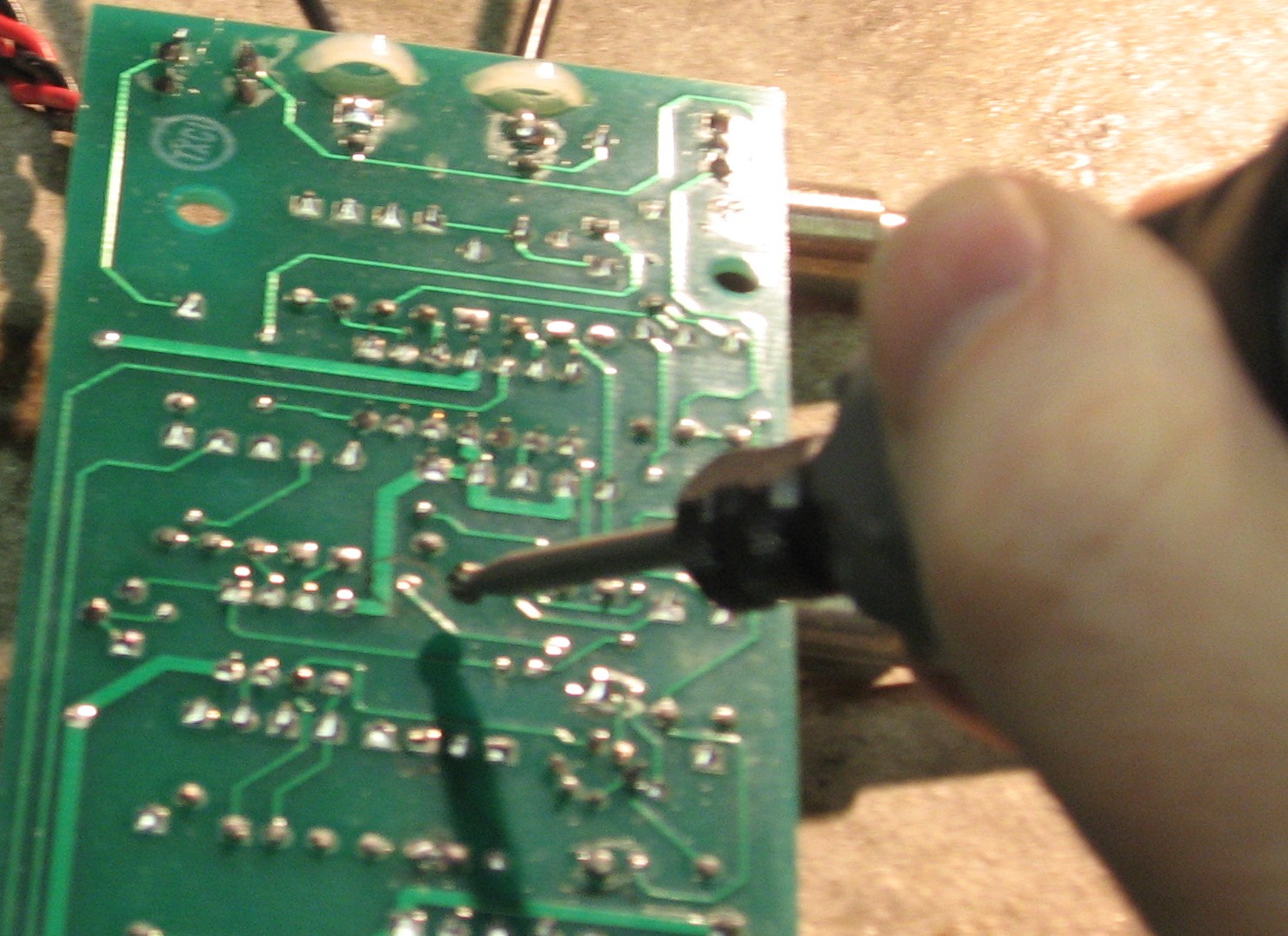
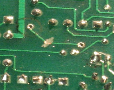
Larry Hendry wrote: "Just as with my MOTM-300, I found the fine tune range on my MOTM-310 too wide for my personal preference. On the unmodified MOTM-300, it is about 11 semitones. I changed mine to 4 semitones. See my MOTM-300 modification document for details. I found the unmodified MOTM-310 fine tune to have a range of 8 semitones. I wanted to change that to approximately match my modified MOTM-300 range of 4 semitones. The change is again simple (although applied differently than the MOTM-300). You have two easy choices:
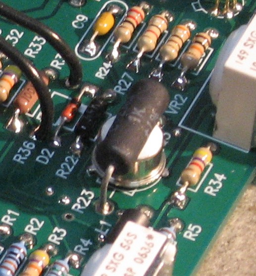
The resistor addition is very near the tempco resistor...
...This modification is easily reversible. You can restore the cut trace by soldering a resistor lead between the two via holes where we are installing the 4.7 Meg-ohm resistor." |
||
2. VCO Tracking Mod. |
||
|
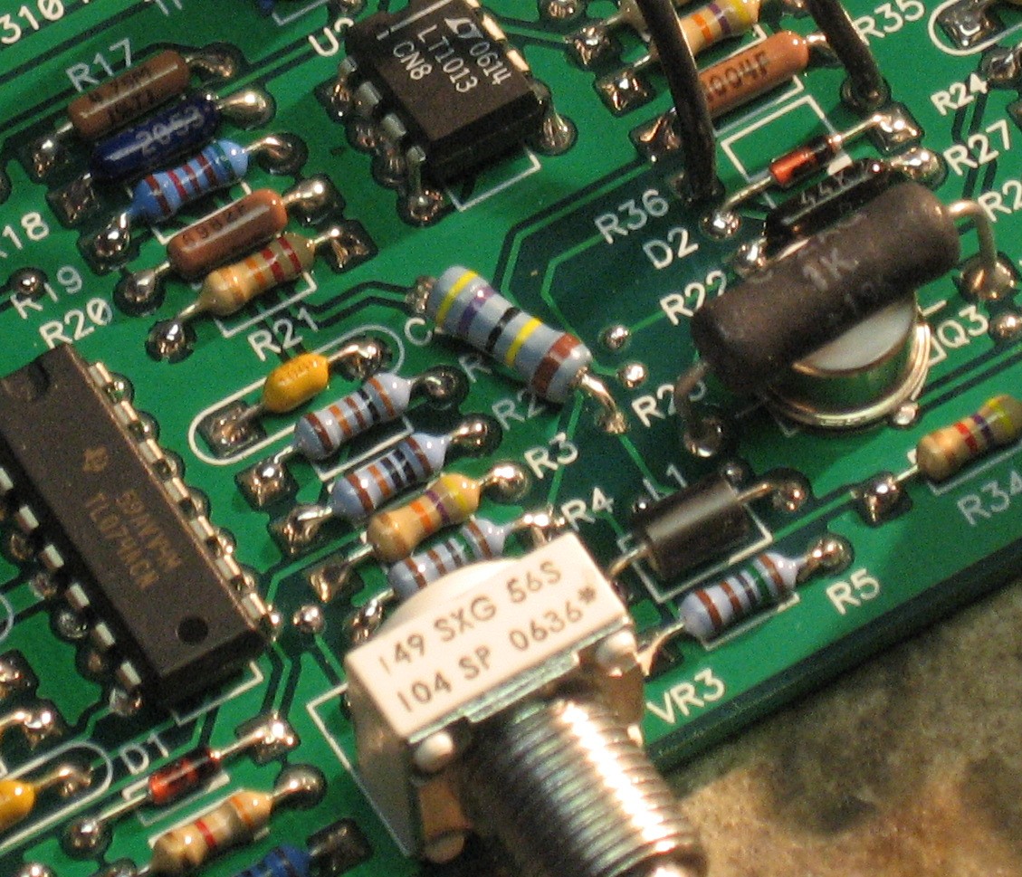
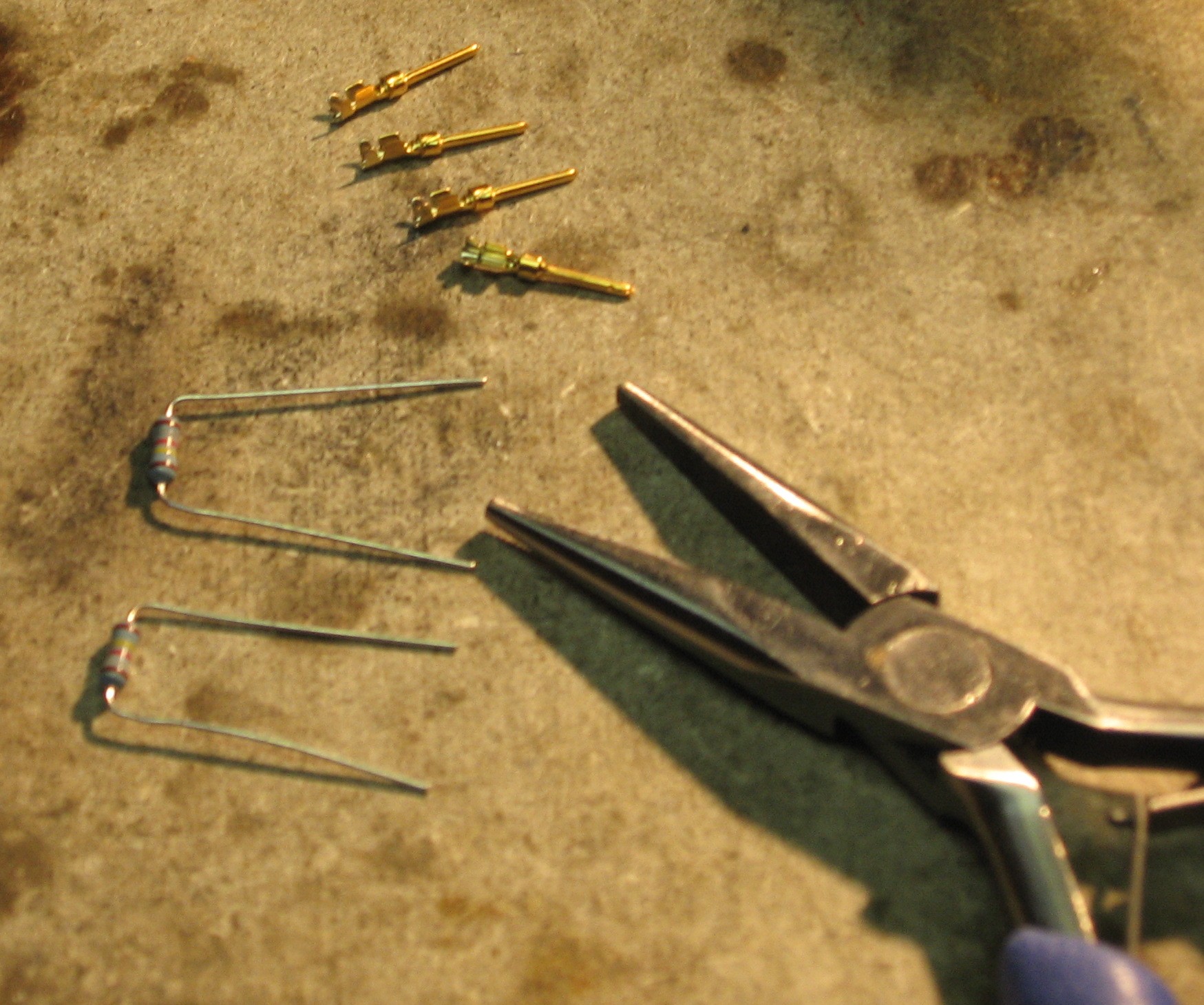
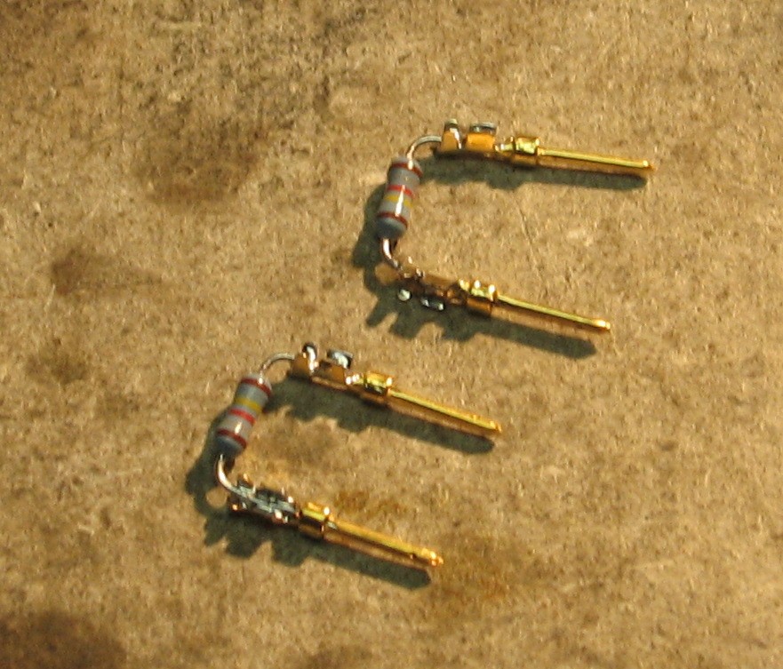
Larry Hendry presented a procedure for tweaking the VCO tracking developed in 2002 by Paul Haneburg. The procedure involves determining a value for R36 that provides the best tracking for the specific VCO and you can download Paul's detailed procedure instructions here. So for now, we're going to leave R36 out. We'll put clips in there like we did for the 300.
|
||
Parts |
||
|
In 2008 (or about that time), Synthesis Technology stopped producing full-blown kits, and moved toward what Paul calls "2.0" (two-dot-oh) DIY. This assumes the builder will buy certain parts from Synthesis Technology - PCB, Panel, and in some cases a Special Parts Kit of the particularly hard to find parts - and will get the rest of the parts from Mouser or Digikey or - well - wherever. For those who are building this as a "two-dot-oh" project, Will and I, with feedback and review from others, have developed a parts-list / bill-of-materials in the form of an XL spreadsheet (as usual). Please don't take it as gospel. We've been over and over it and are relatively confident in our specifications - and we hear that several people have used it successfully so you should be good. The BOM assumes that you get the "extra parts kit" from Synthesis Tech. Synthesis Technology offers some parts like pots and knobs at particularly good prices... these options are offered in the BOM.
Click here to download our XL spreadsheet Parts List |
||
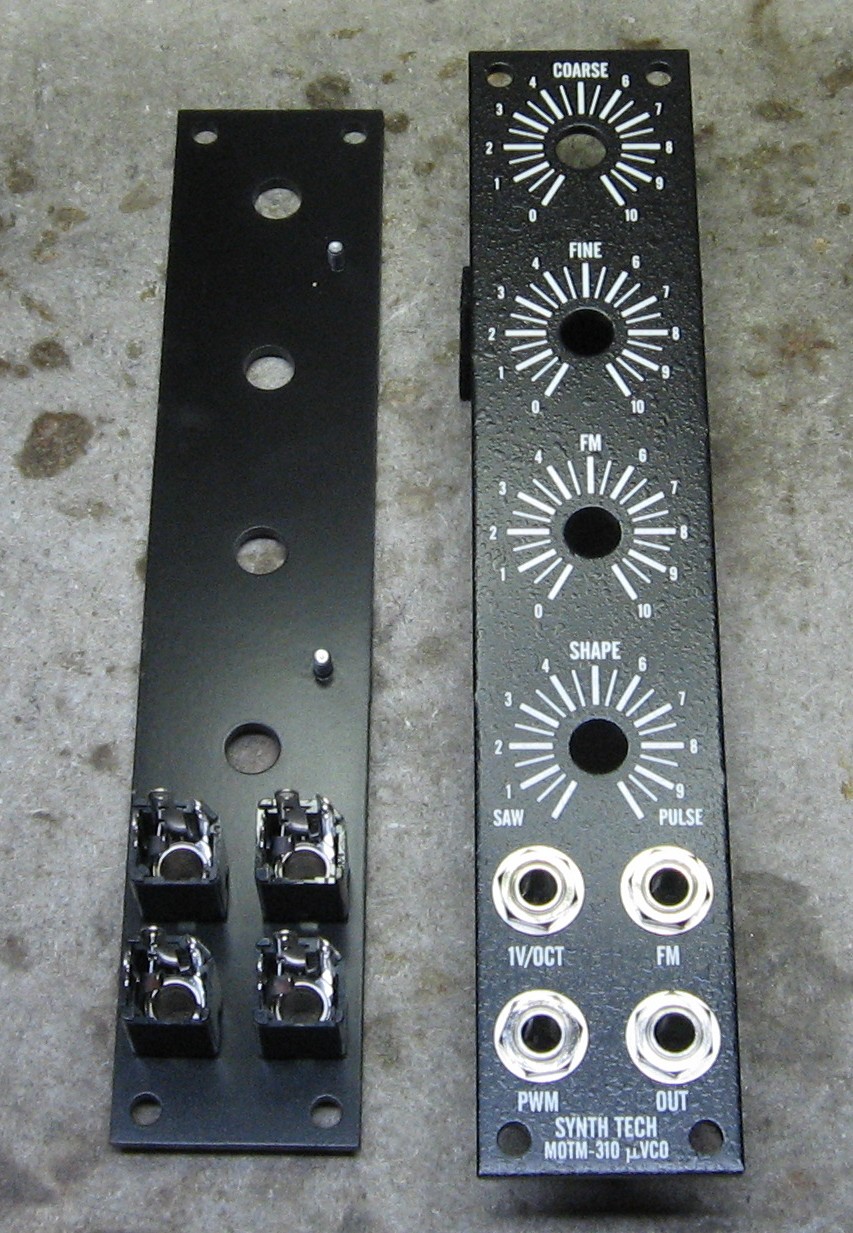
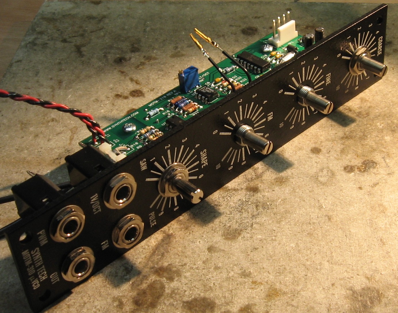
Panel |
||
|
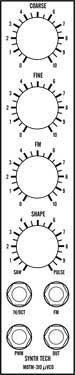
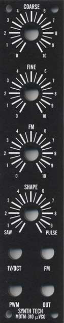
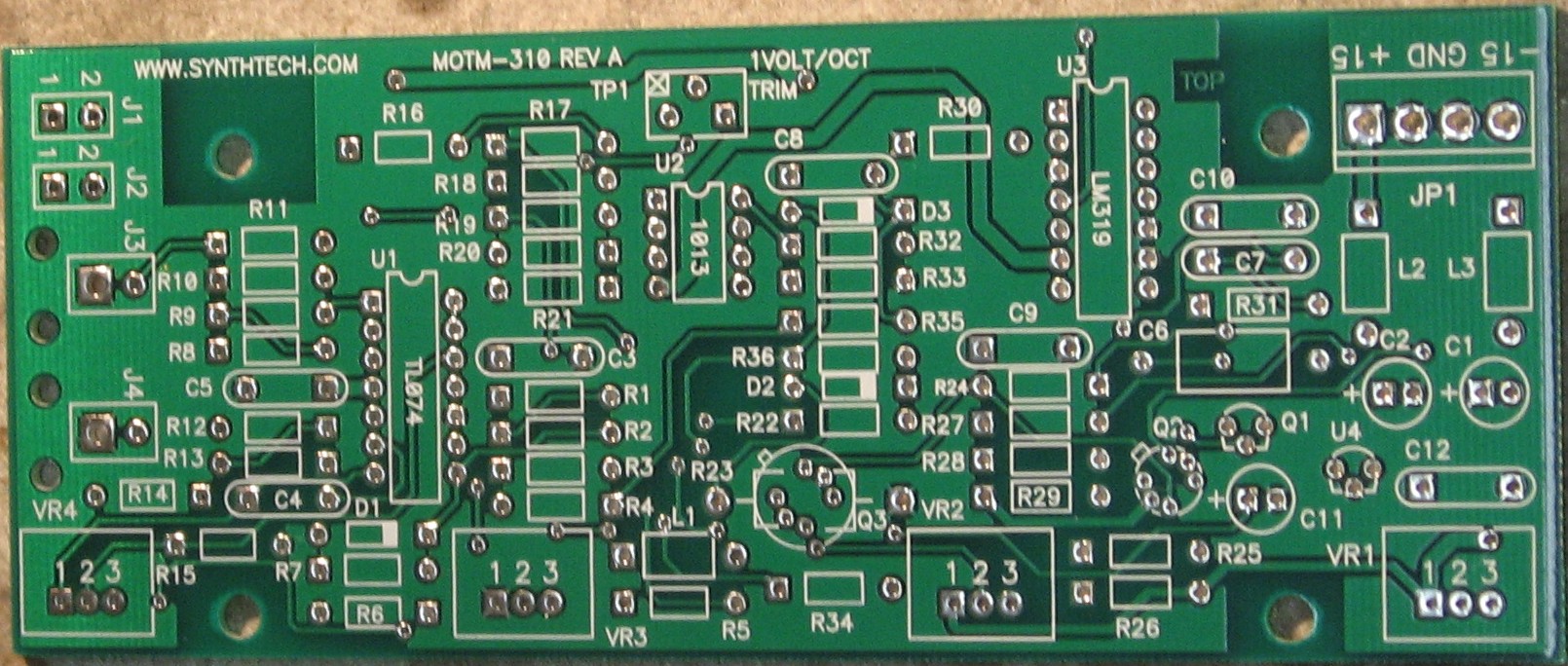
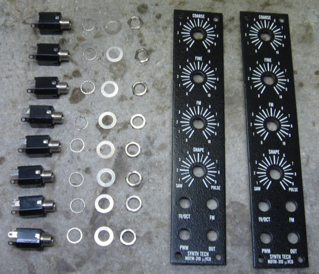
If you're building this as a "two-dot-oh" project, we also assume you get the panel from Synthesis Technology:
|
||
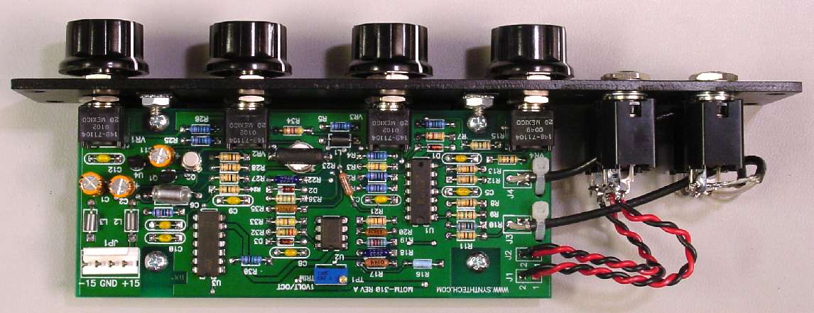
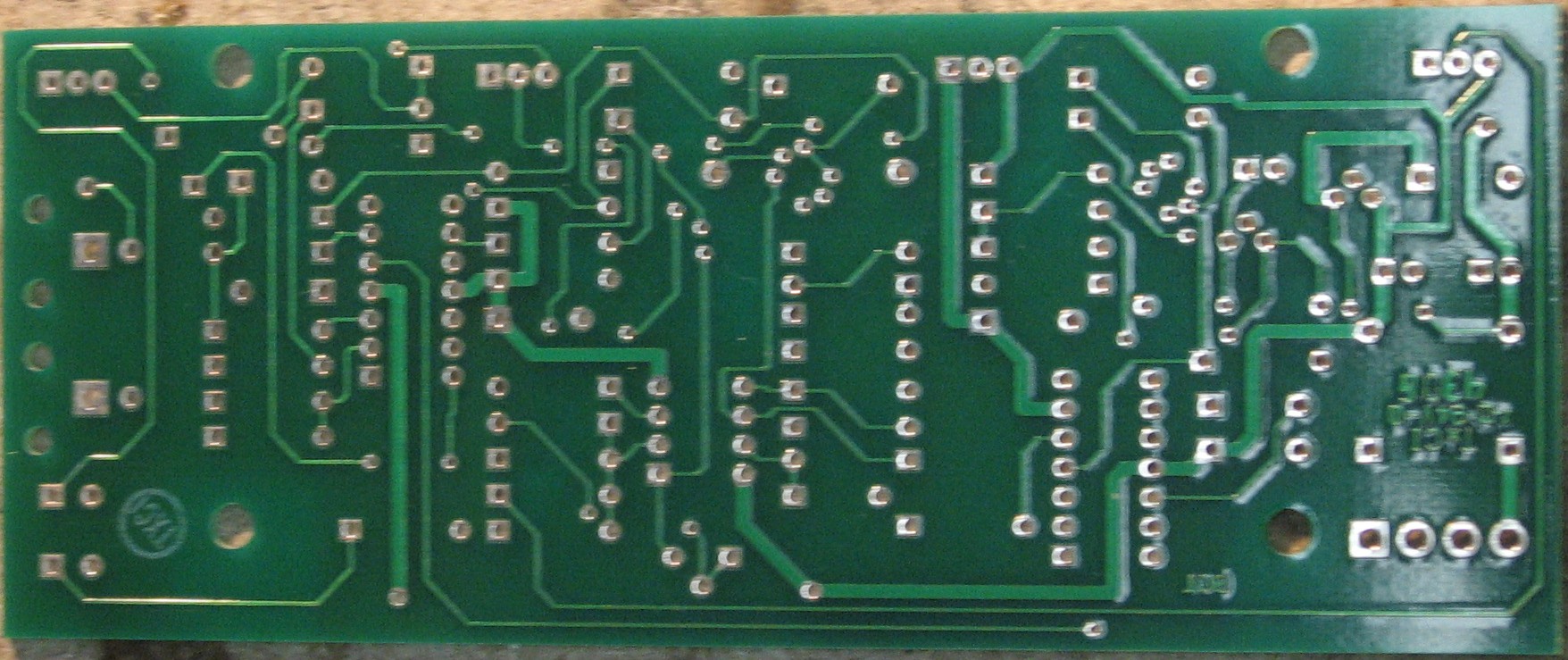
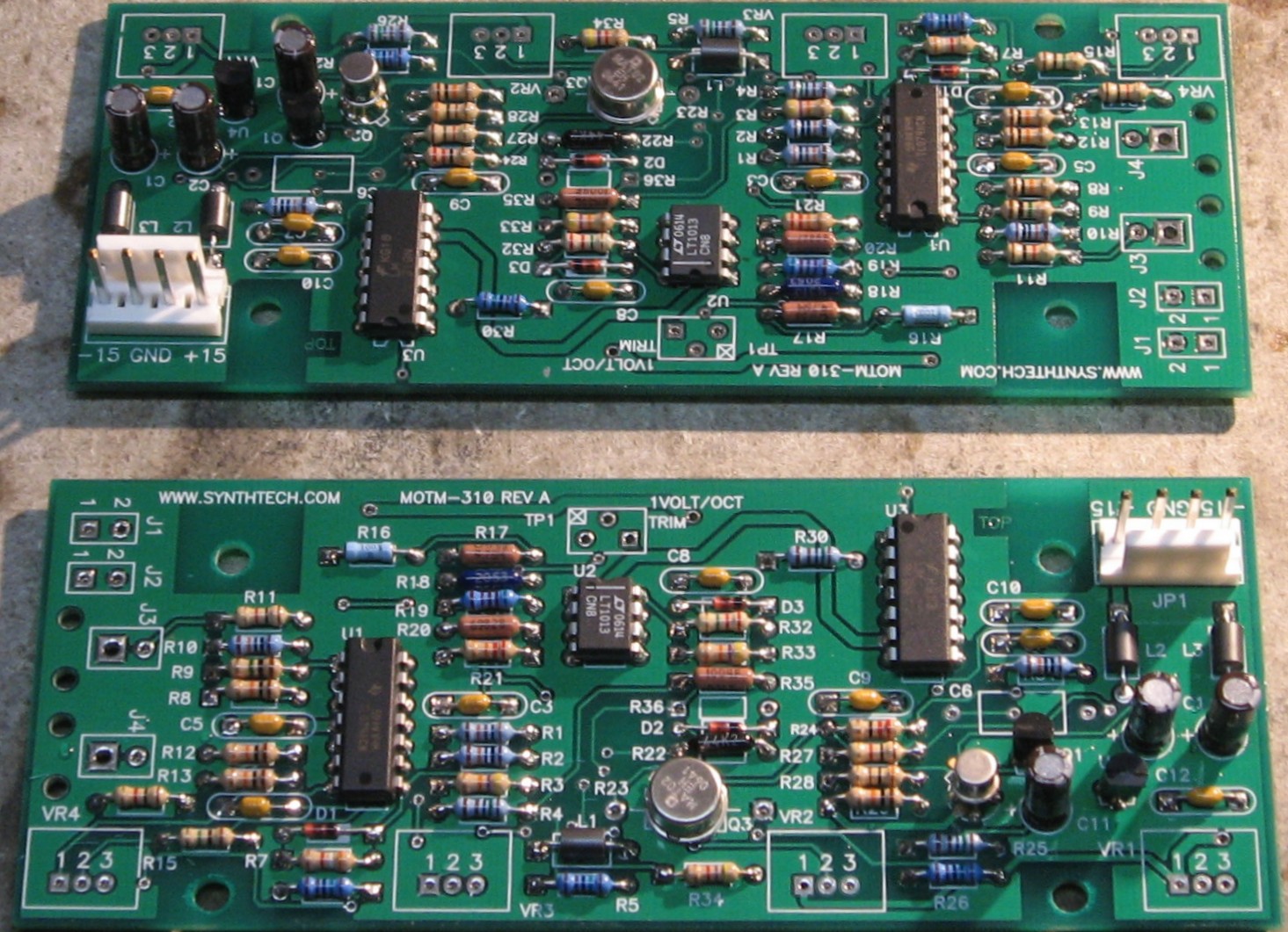
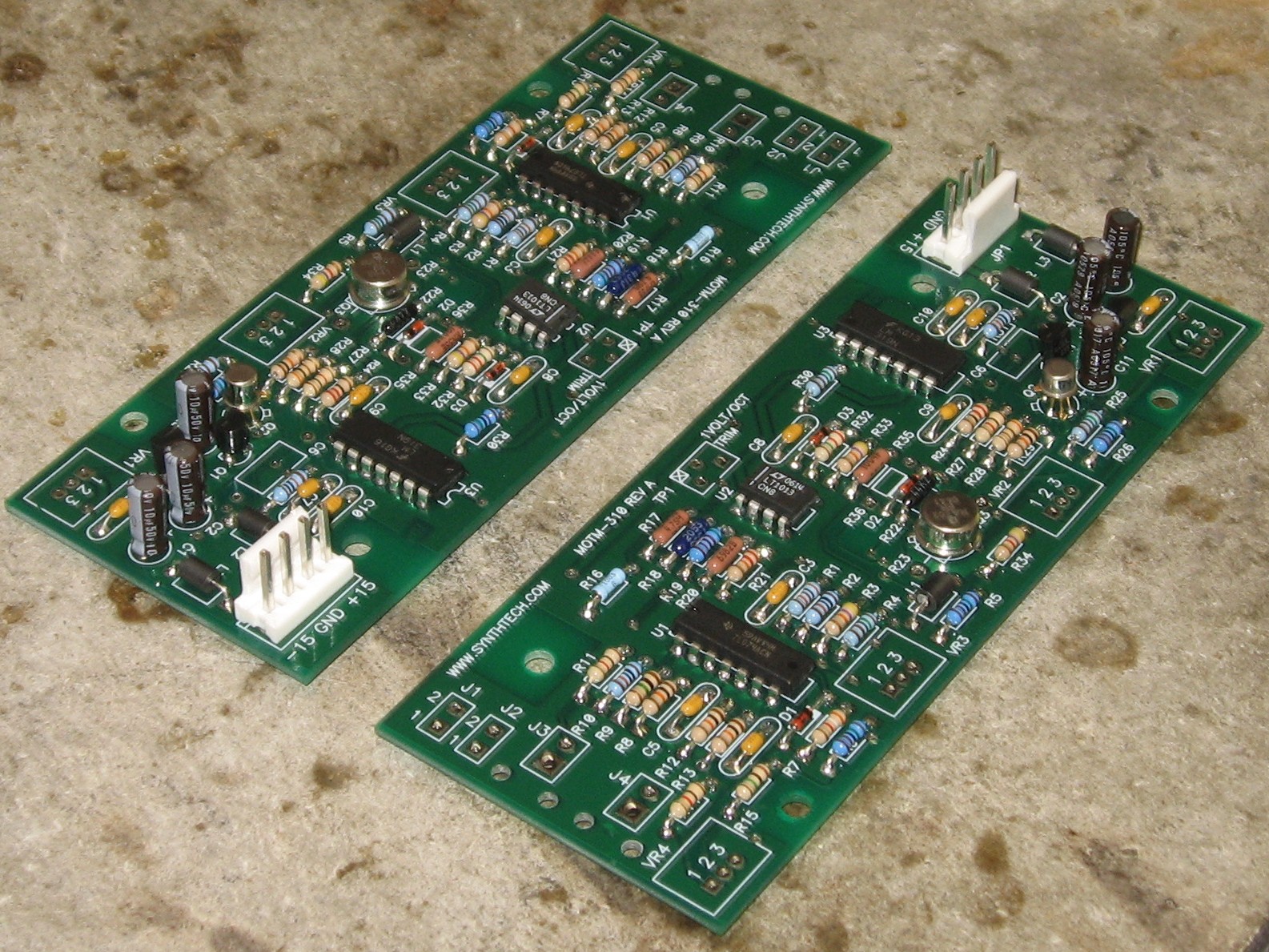
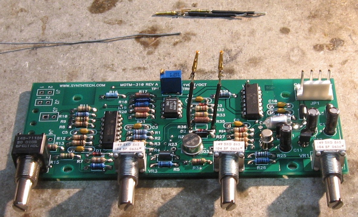
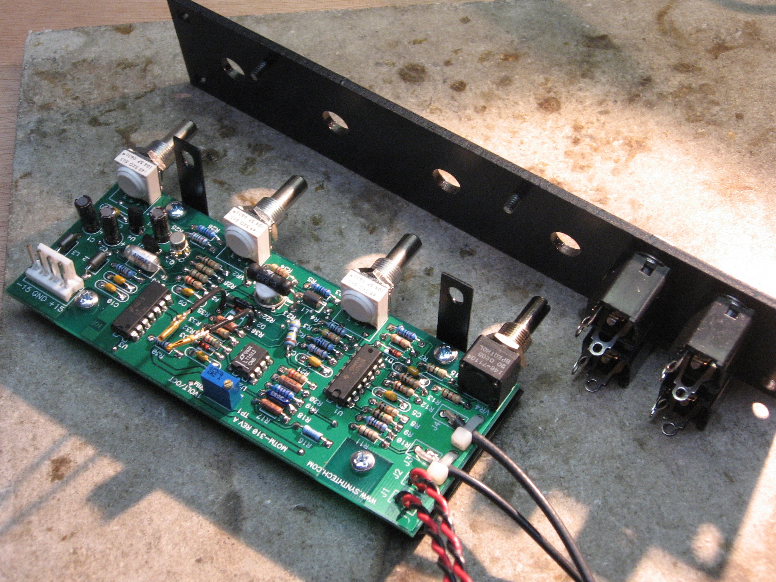
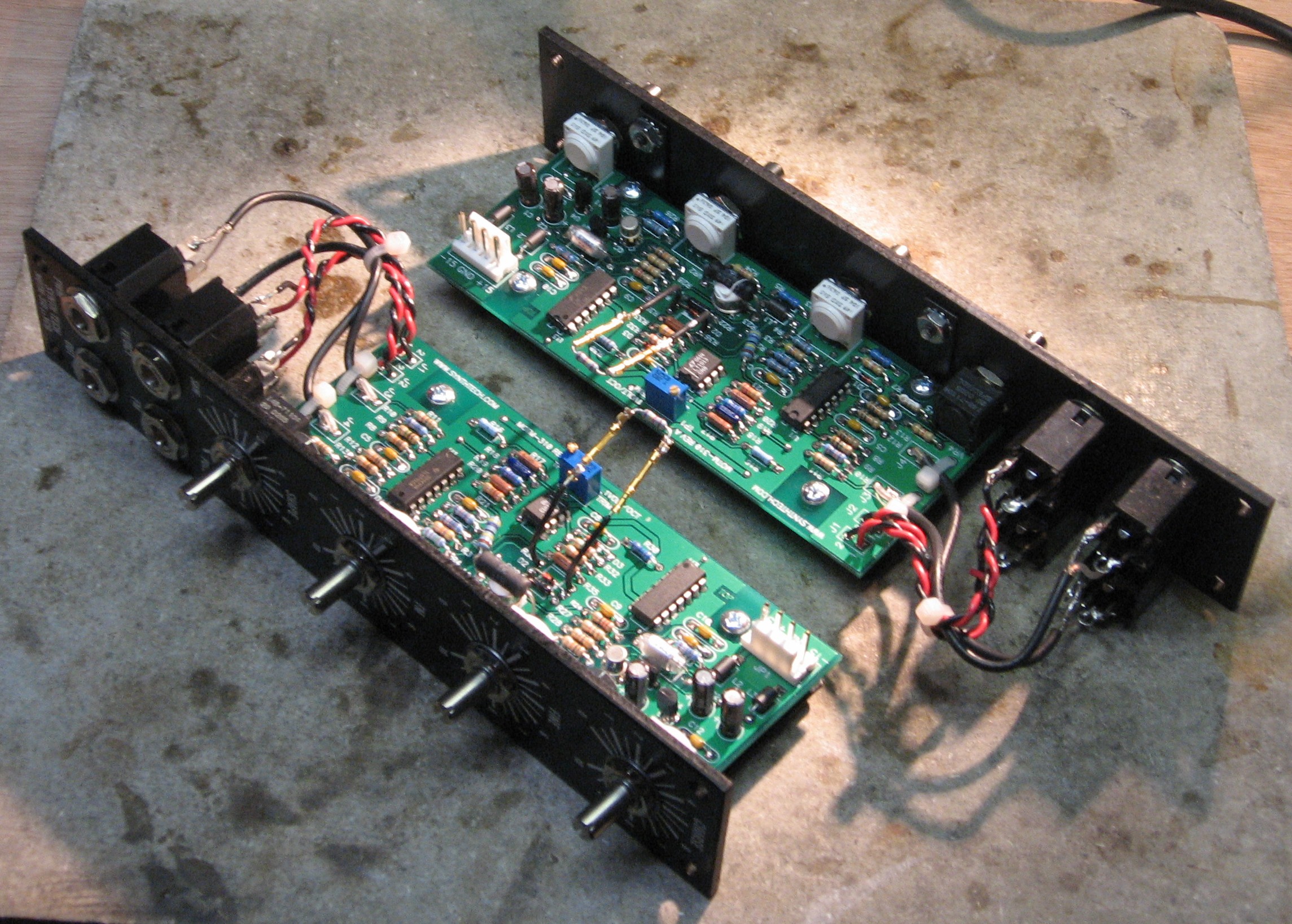
Construction Phase 1All the stuff in Phase 1 gets soldered using "Organic" Solder. At every break in the action, we wash the board off to get rid of the flux. |
||
|
|
||
|
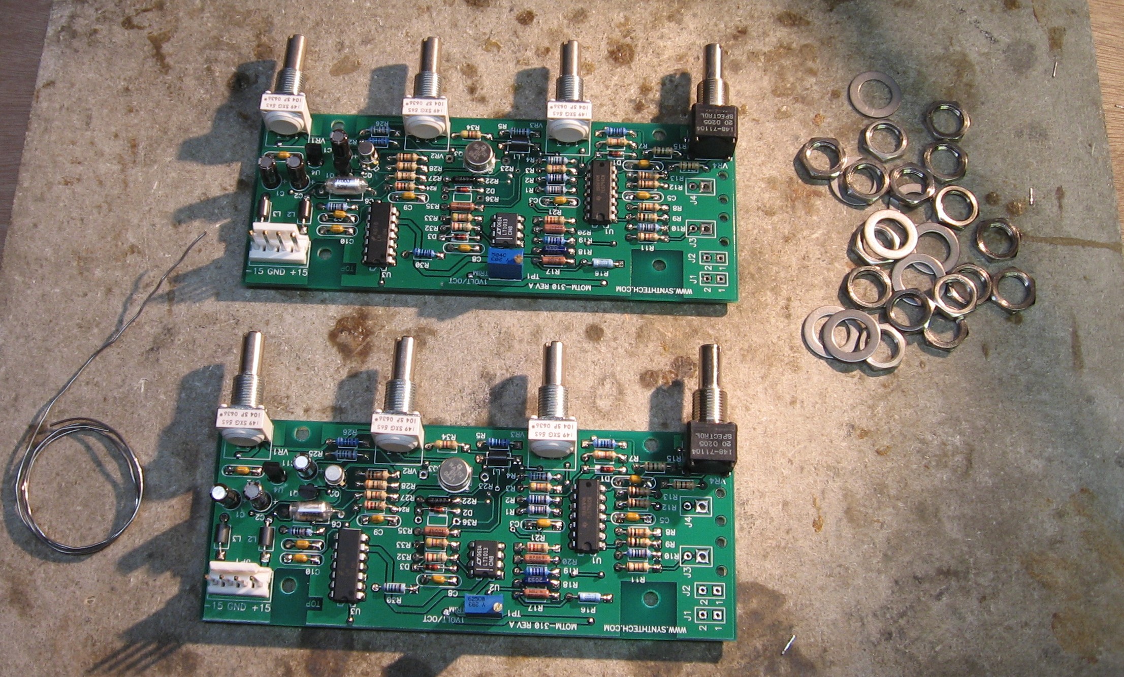
The whole first phase - - |
||
|
|
||
Construction Phase 2All the stuff in Phase 2 gets soldered using "No-Clean" Solder and the PCB doesn't get washed off from here on. |
||
|
Pots |
||
|
|
||
|
R36 wires with sleeves |
||
|
|
||
|
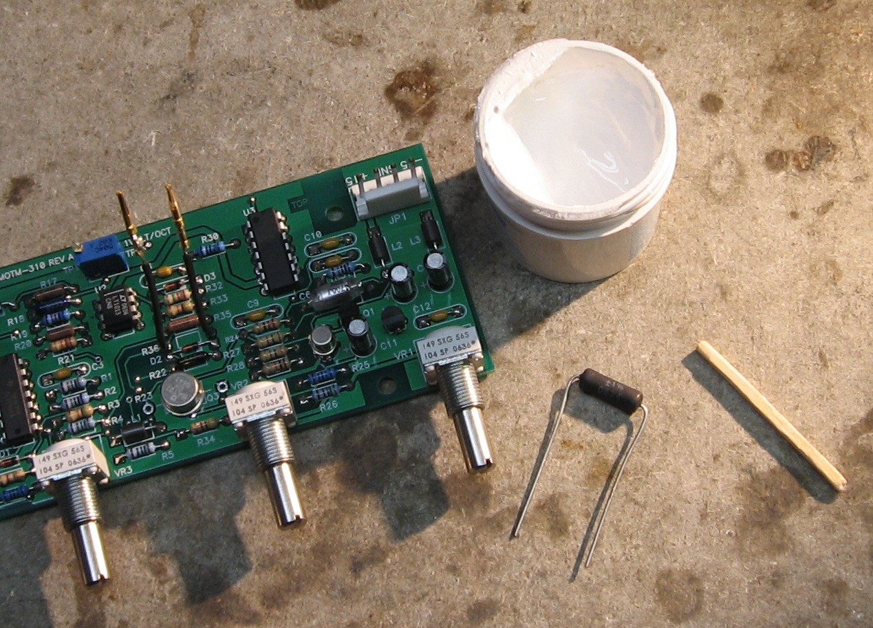
Tempco Resistor |
||
|
|
||
|
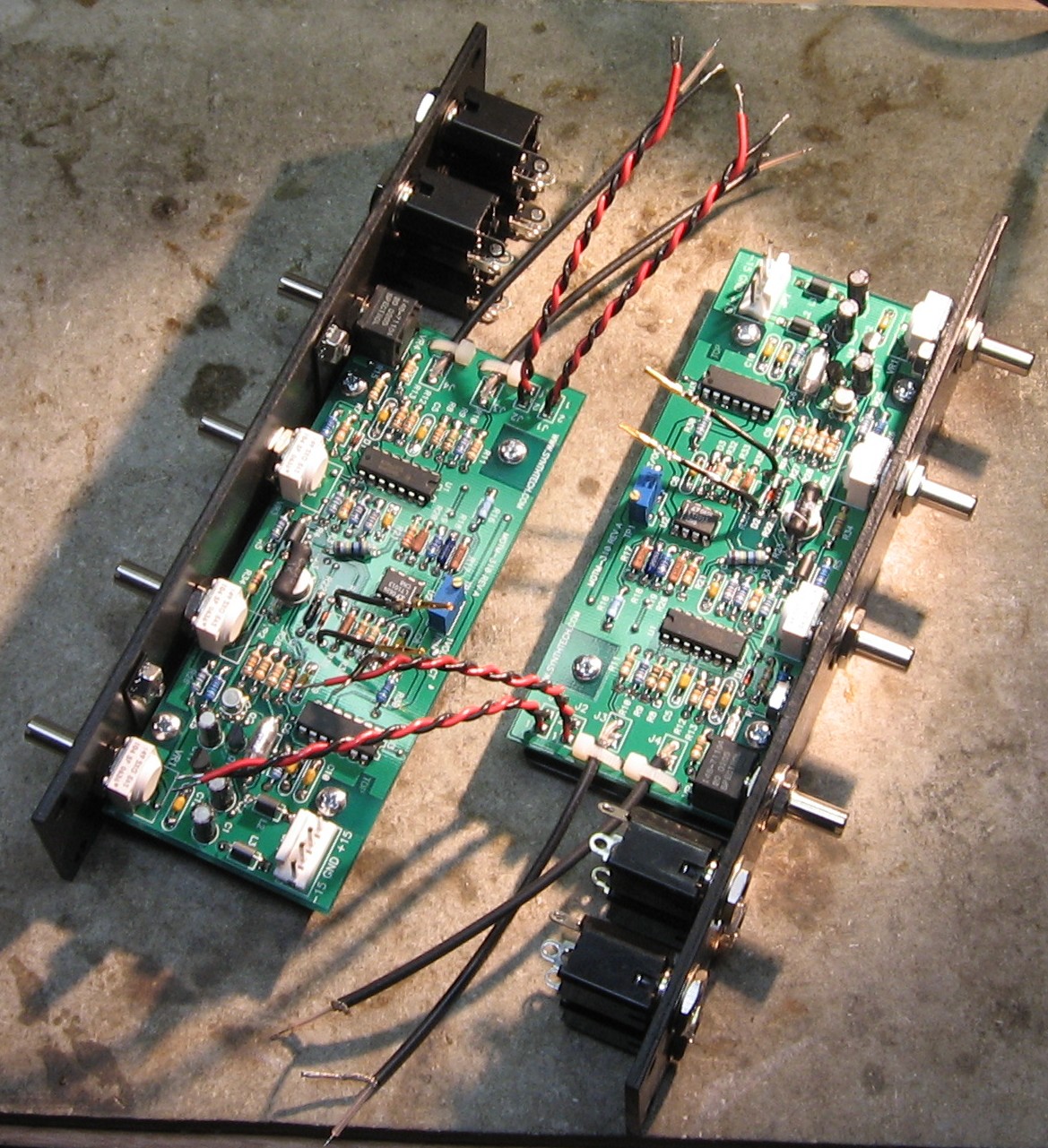
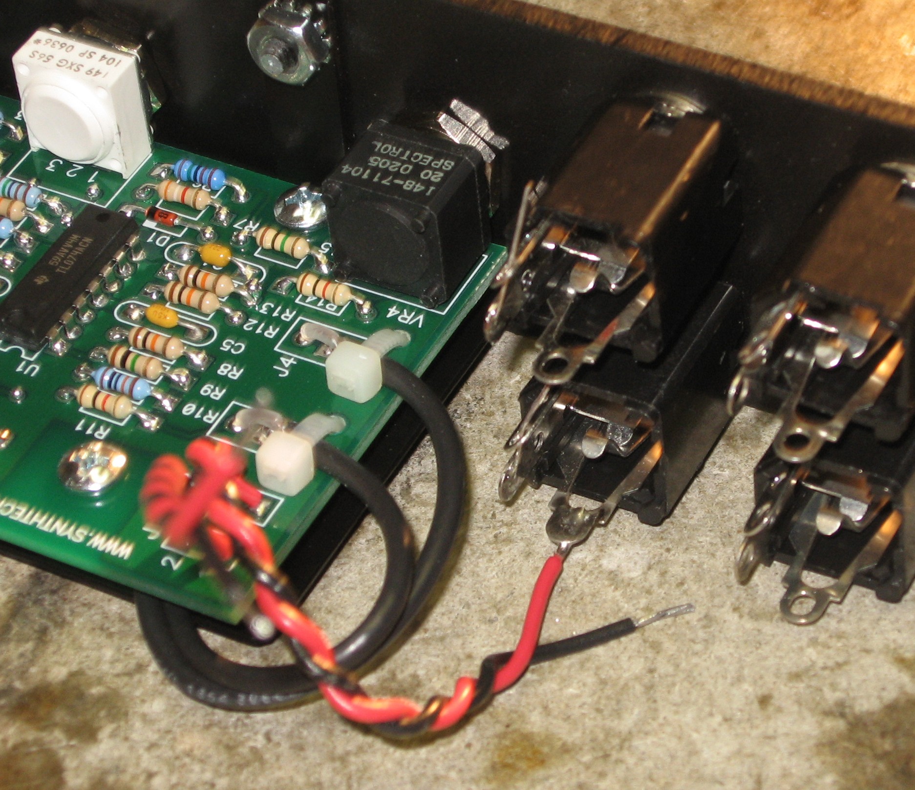
Wires |
||
|
|
||
|
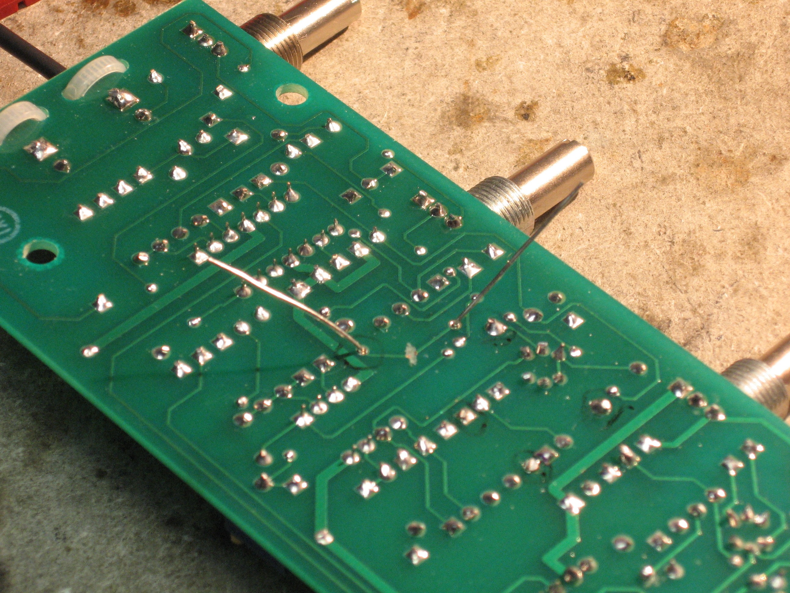
Fine Tune Modification |
||
|
|
||
|
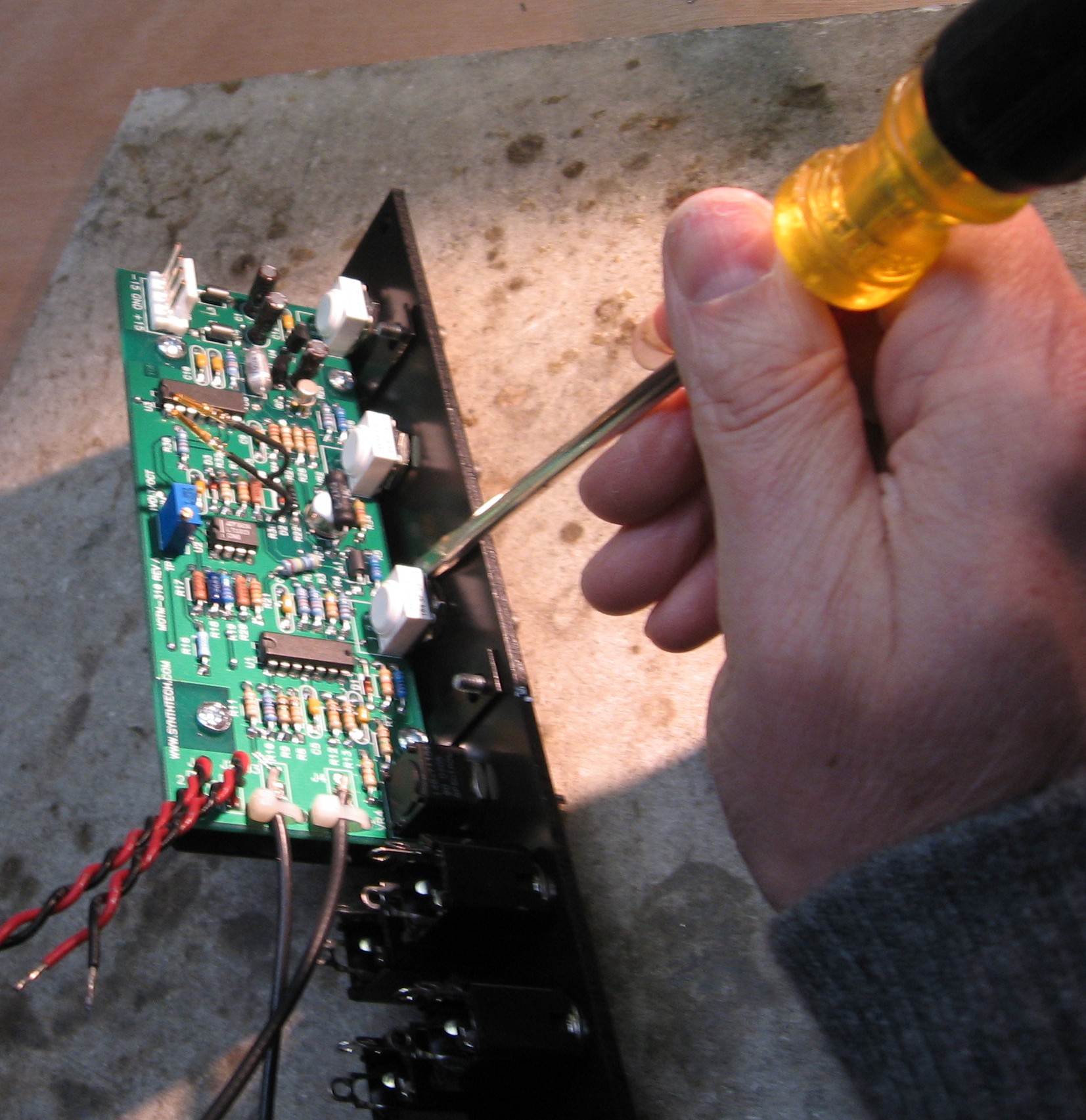
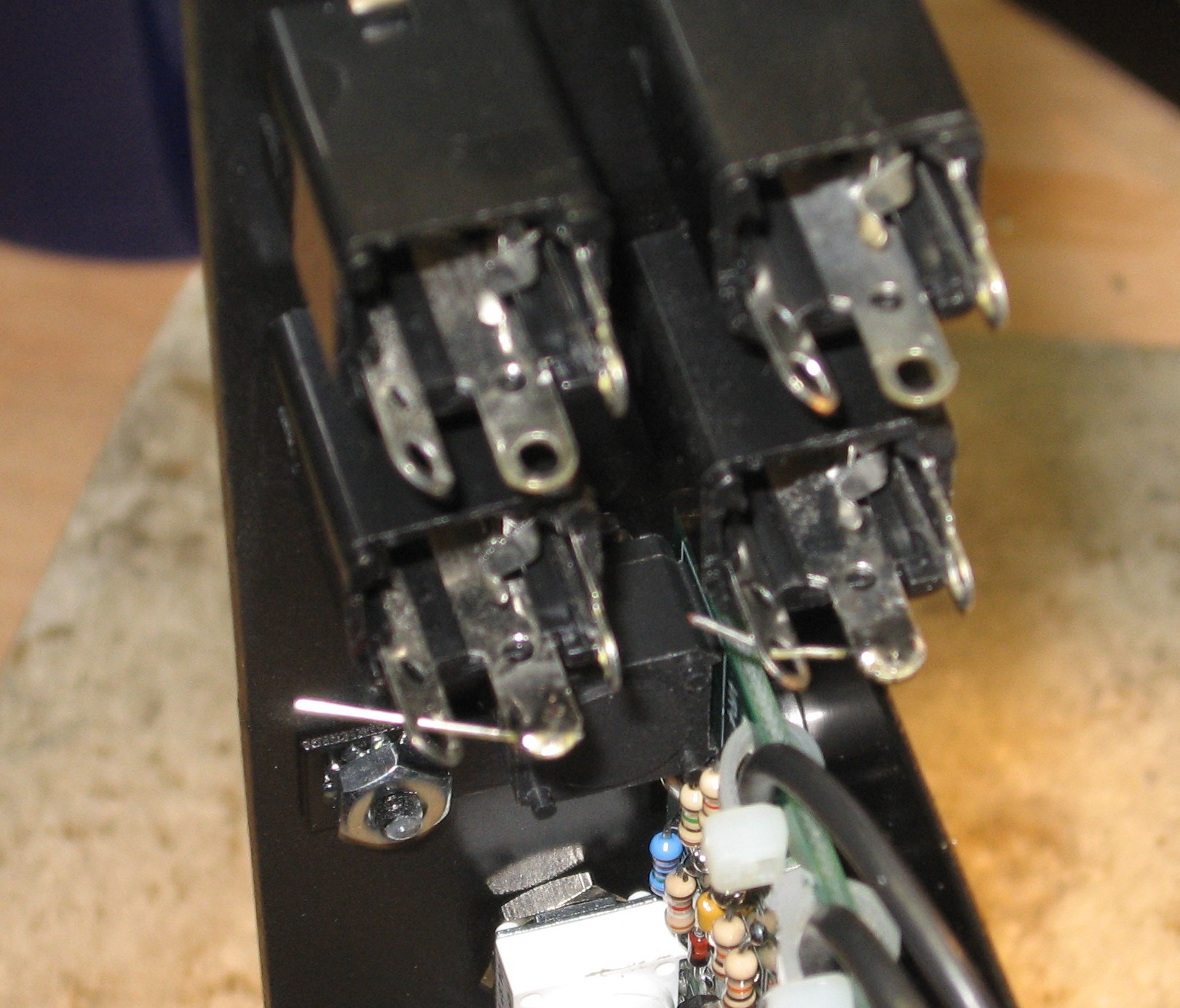
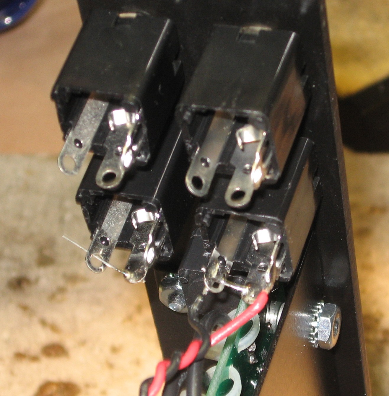
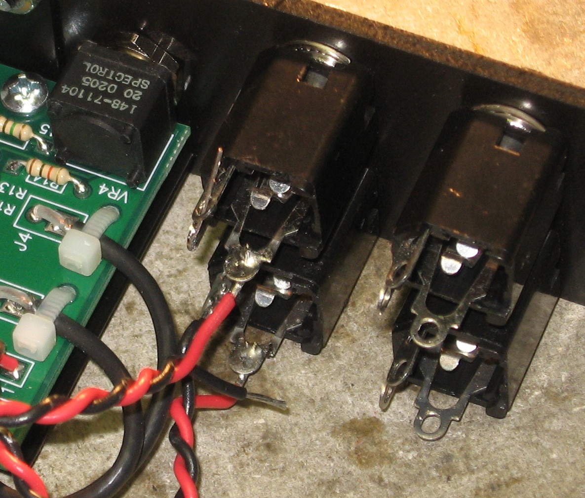
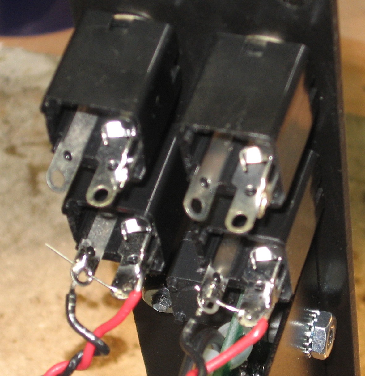
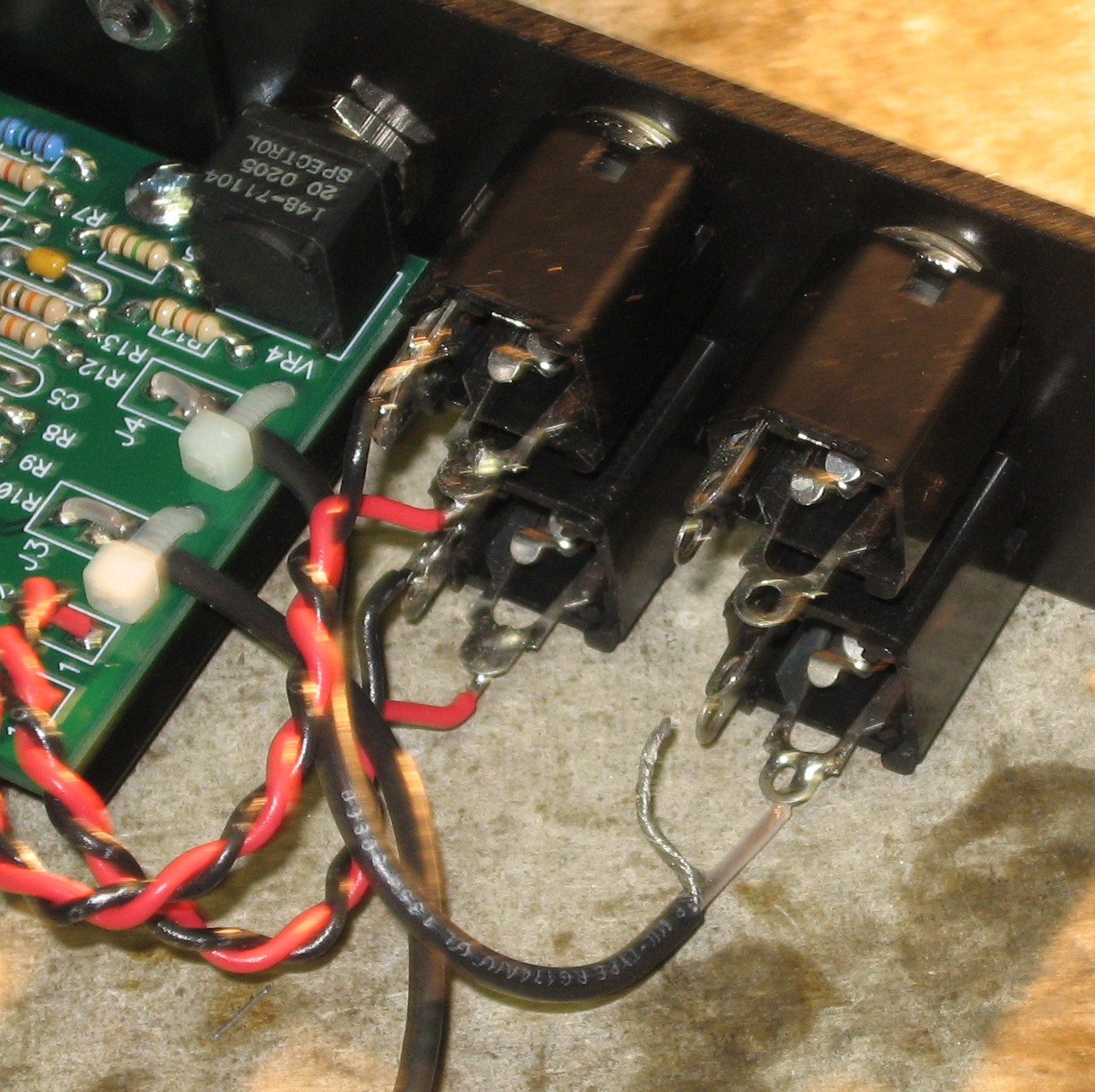
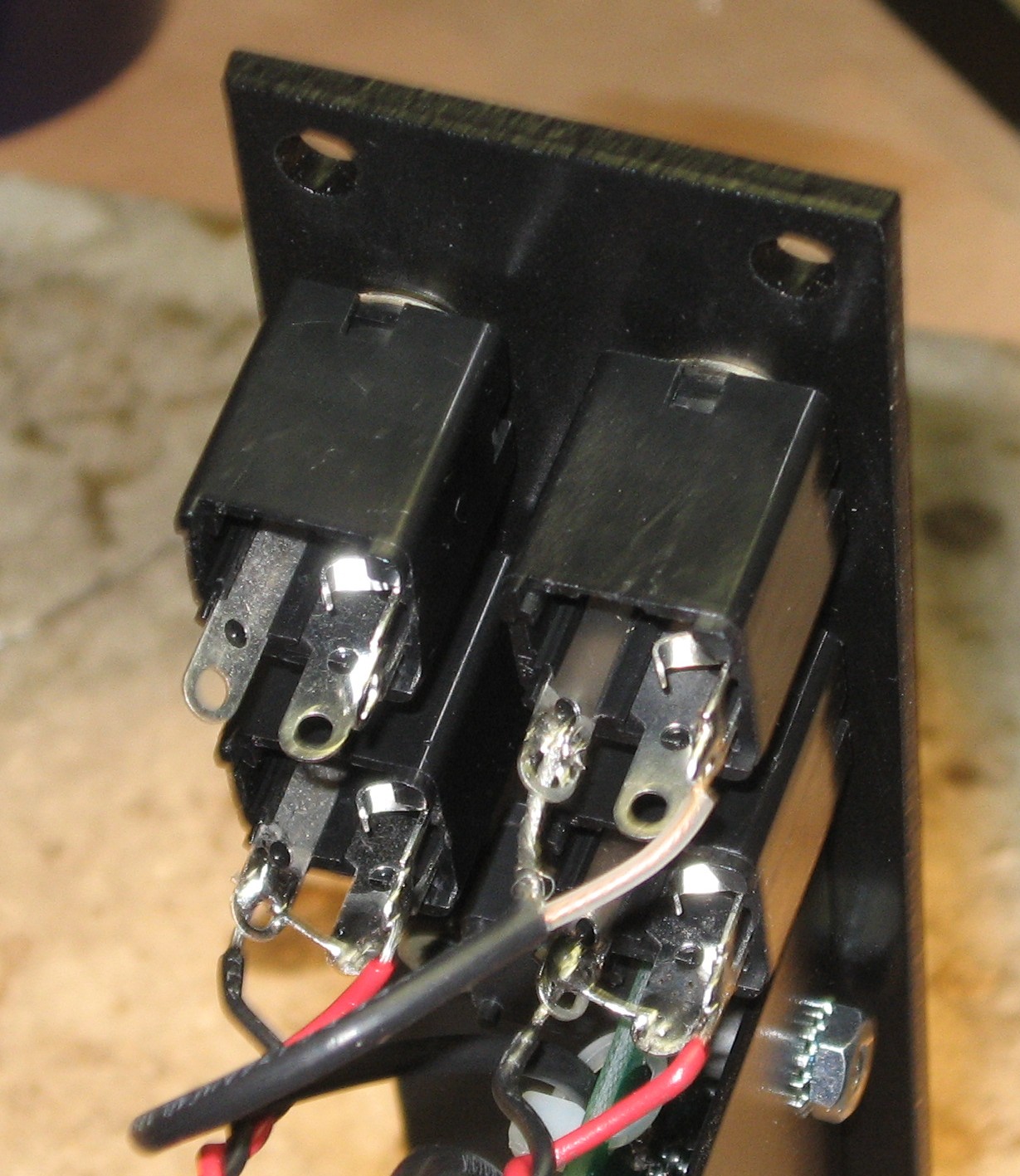
Jacks |
||
|
|
||
|
Bracket |
||
|
|
||
|
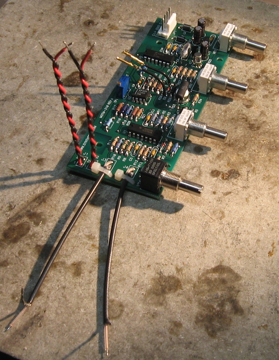
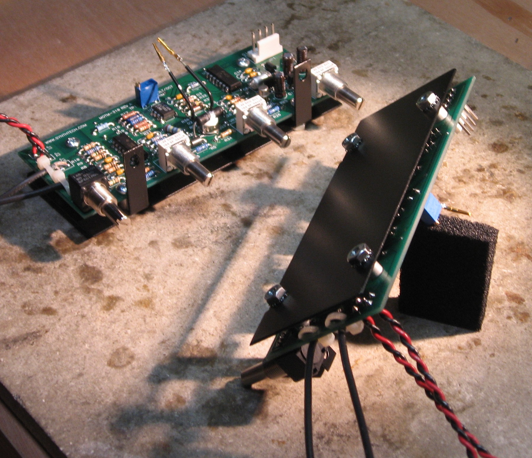
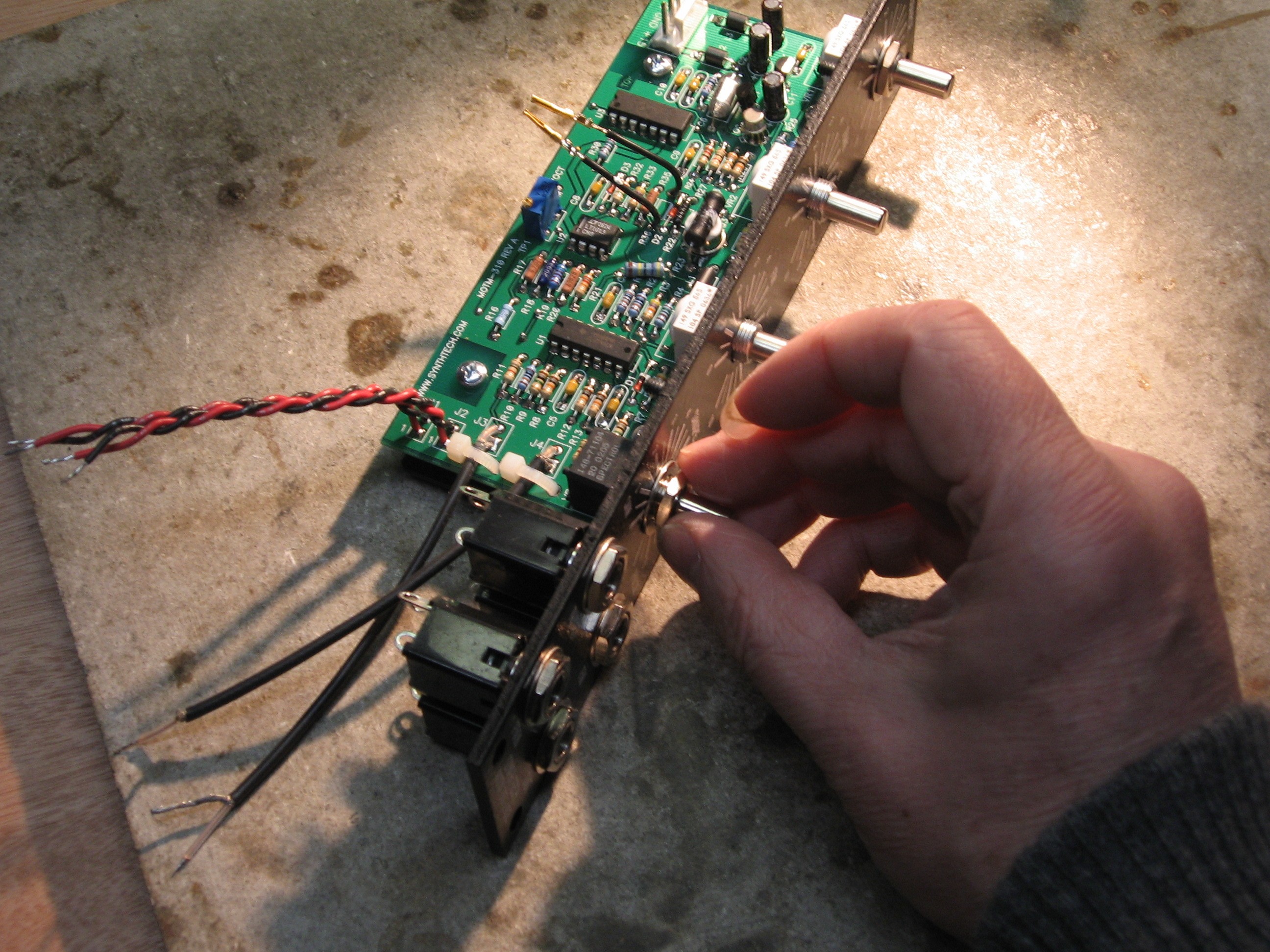
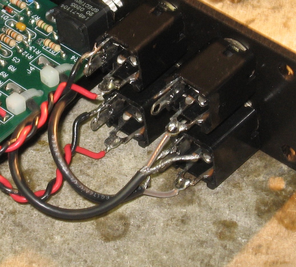
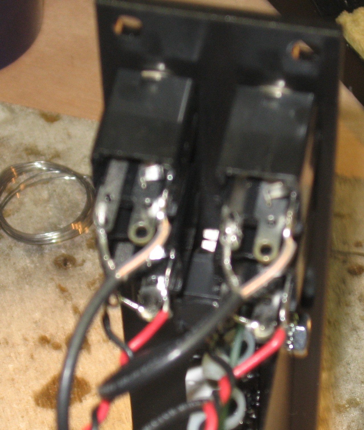
Panel Connections |
||
|
Here's the order in which we connected the jacks - it's different than Paul's instructions and worked better for us.
|
||
|
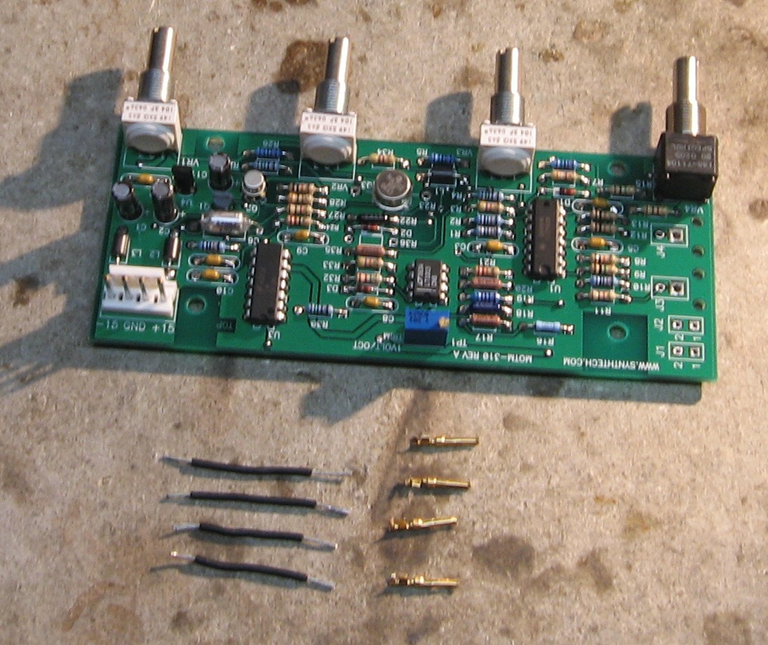
R36 resistors with pins |
||
|
|
||
|
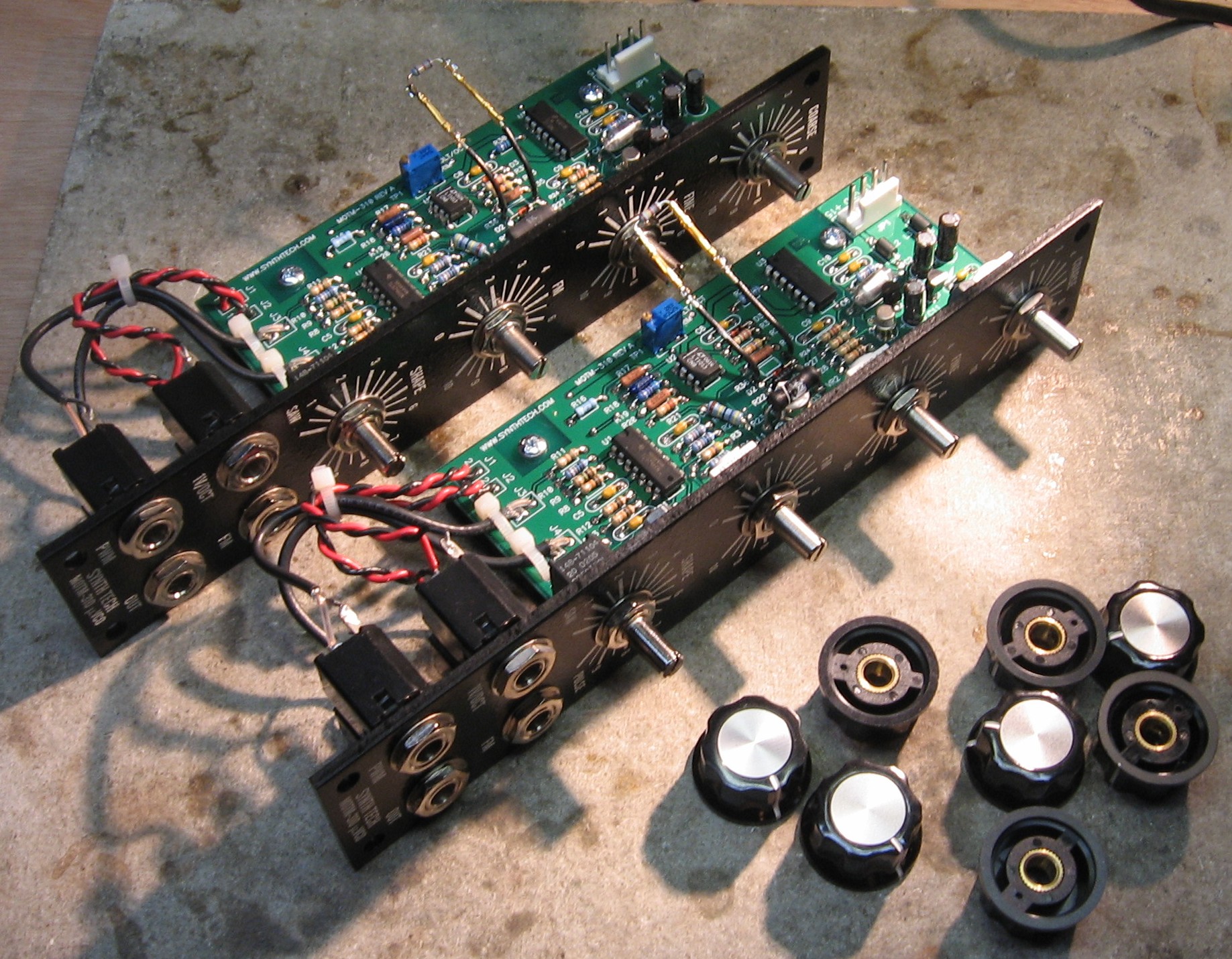
Knobs |
||
|
|
||
|
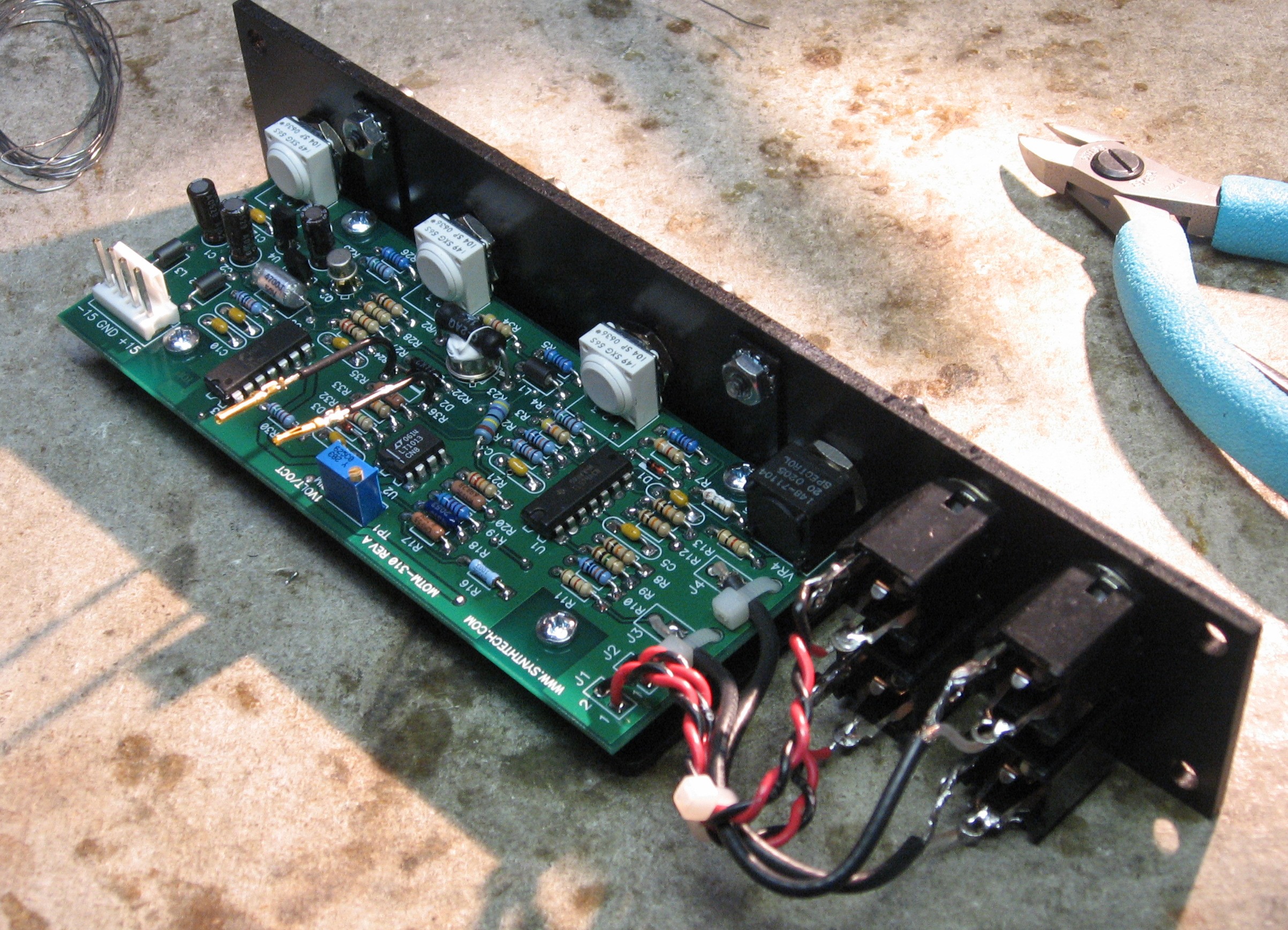
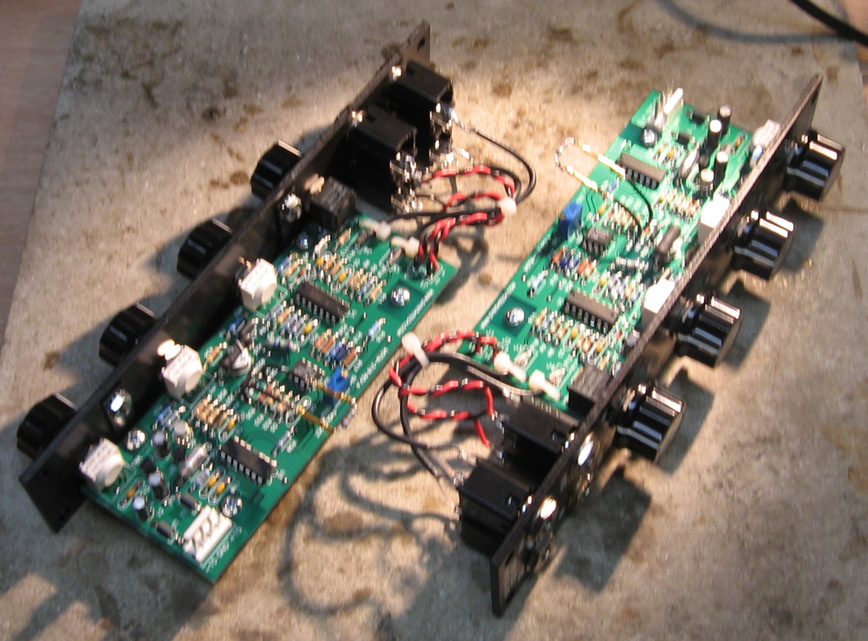
Construction done! |
||
|
|
||
Set up / Testing |
||
Use Notes |
||
|
|
||


|
The fine Print: Use this site at your own risk. We are self-proclaimed idiots and any use of this site and any materials presented herein should be taken with a grain of Kosher salt. If the info is useful - more's the better. Bill and Will © 2005-2011 all frilling rights reserved
|