Bill and Will's Synth
|
Table of Contents |
|
Here's a table of contents that we hope will make this page easier to traverse: Background - presents an explanation and Jurgen's initial description of the effect Recapitulation of Construction/Feature Options - presents a simple list of the different possible implementations Parts - presents a Bill of Materials and notes about it Panel - presents our FPE panel design - ultimately perhaps Scott Deyo at Bridechamber will fabricate one Construction Phase 1 - Resistors, Capacitors, IC Sockets, Power Plugs, MTA headers Construction Phase 2 - Trimmers - OK, this is where we've left off for now |
Background
|
|
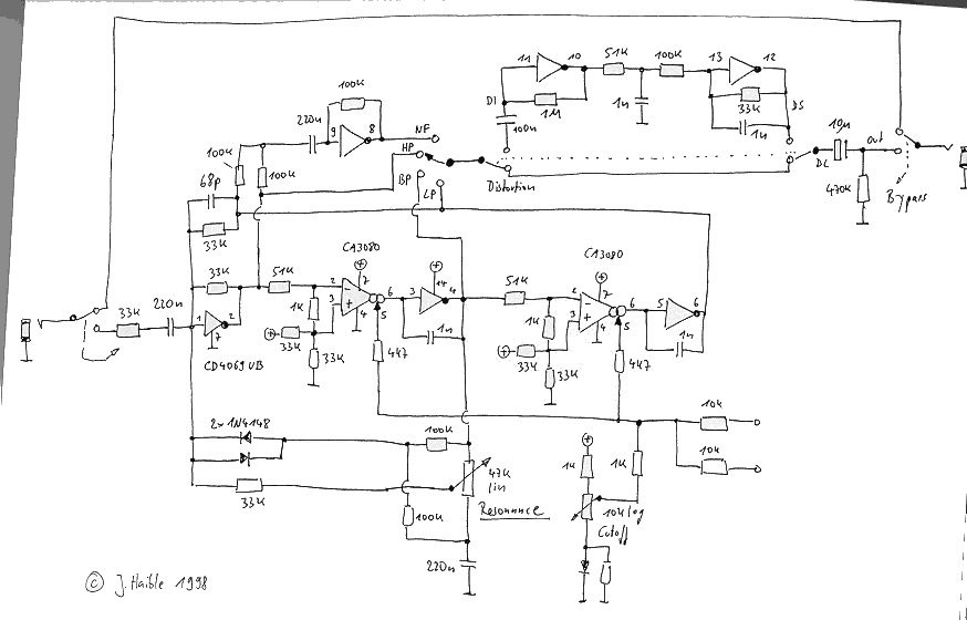
Jurgen writes about the module on his site: "It sounds considerably different than the ordinary SEM-type state variable filter. The maximum Q is lower on the Wasp version. And there is an additional distortion coming from the CMOS inverter nonlinearities. This distortion is gradually increasing with input level, and you can slightly hear it way before the circuit actually clips. The CMOS inverters seem to be the dominant source of distortion; the CA3080 input dividers are rather on the save side. (100k / 1k ; but remember the absolute maximum voltage swing is limited to 5V anyway.) I have replaced the 100k resistors with 51k without noticeable increase of distortion. "Ok, the Wasp Filter sounds different than other state variables. But what is it good? IMO, every filter's overdrive characteristic has its own special applications. The SSM2040 in LP configuration, for example, is unbeatable when you want to process a full chord of buzzy "Jump"-type saw voices. The Wasp Filter works best on Farfisa-type *organ* sounds. I tried various sounds from my OB-8, and really, the best results came with bright organ sounds. My favorite patch is the filter in LP mode with medium cutoff, and then an envelope with slow attack opening the filter (resonance quite low). This certain "edge" that is added by the filter's distortion is hard to describe, but very pleasant. "I had this circuit at the breadboard first, and I was so pleased with its sound that I build it again on a tiny veroboard. The whole filter consists of 3/6 CD4069 and two 3080's, counting the active components. I built a notch filter from another 1/6 CD4069 (add HP and LP), a heavy distortion section (1/6 4069 with 1meg feedback resistor, and 100nF input capacitor without series resistor), and a fixed 2pole, 5kHz LPF from the remaining 1/6 4069 as a speaker simulator for the distortion section. Now use the SVF to preshape the frequency response of some input signal, and then go into the overdrive / speaker simulator. LPF, BPF and even HPF settings sound pleasant thru the overdrive, with or without resonance. For some reason the notch filter doesn't work well in this configuration. (But it makes a great "one notch phaser" without the overdrive, and controlled by an LFO.) "I was really astonished what you can get out of one single CMOS chip (the OTAs just act as variable resistors, so they don't get much credit here.)"
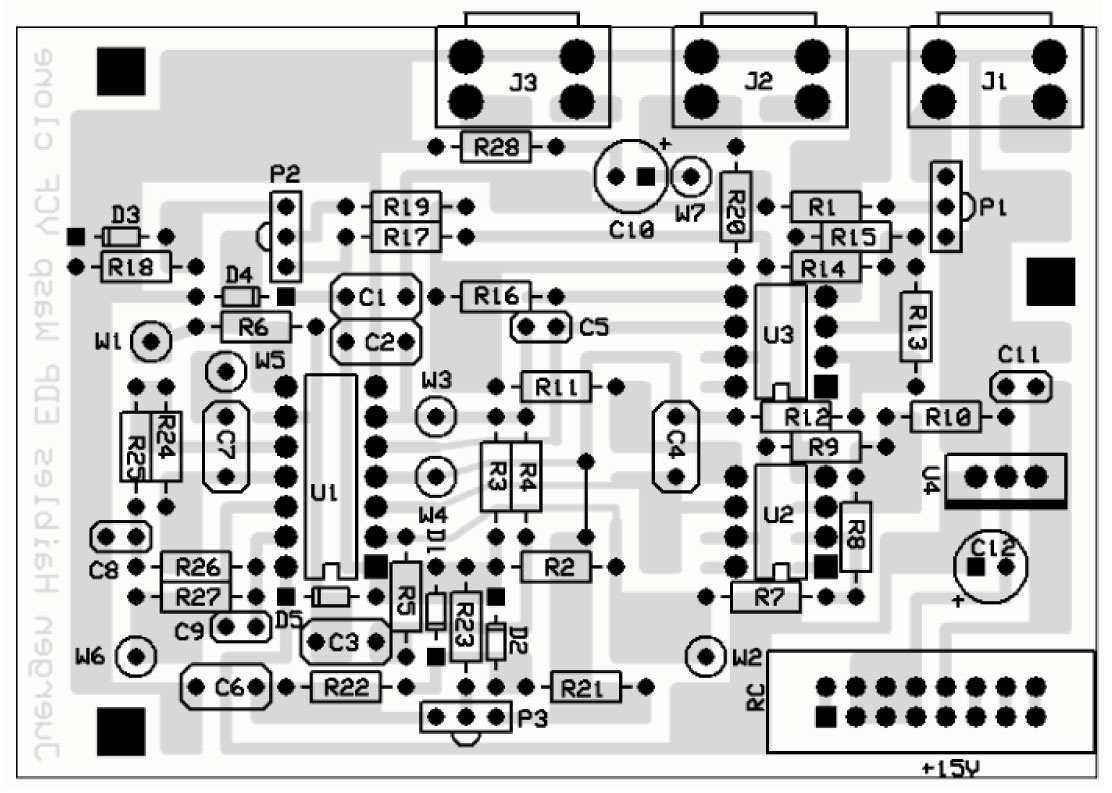
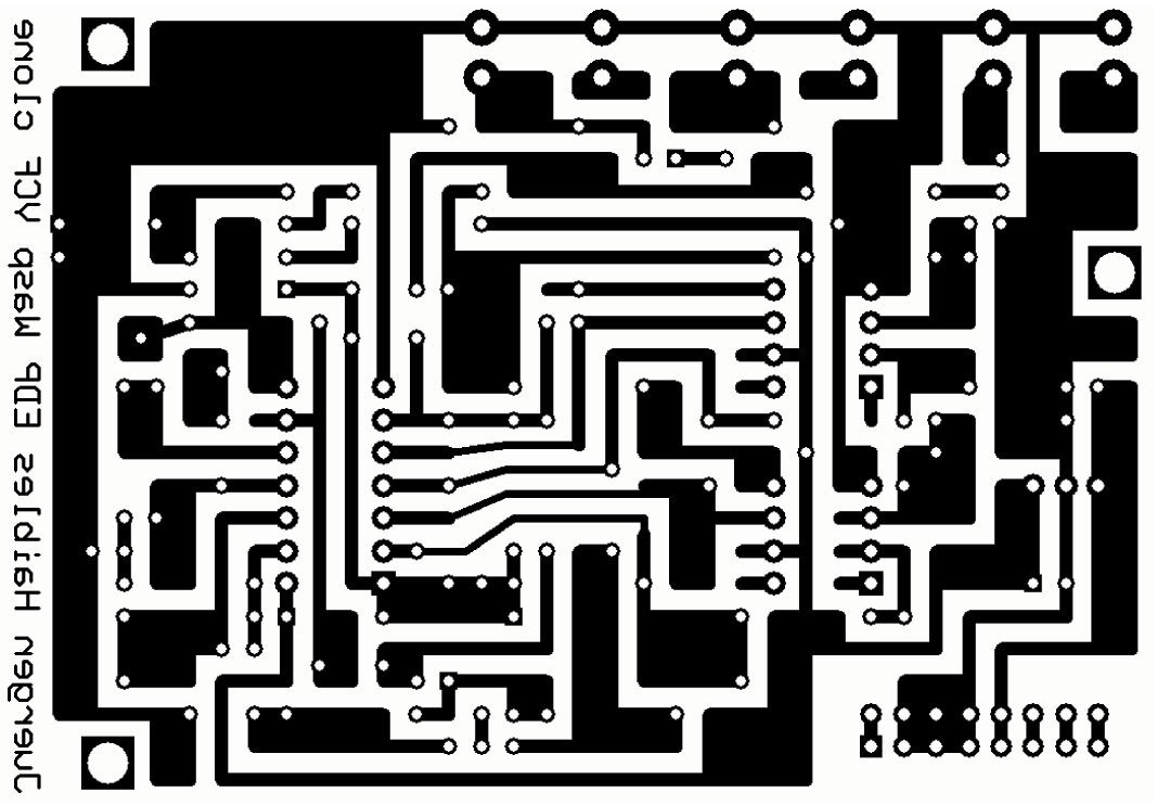
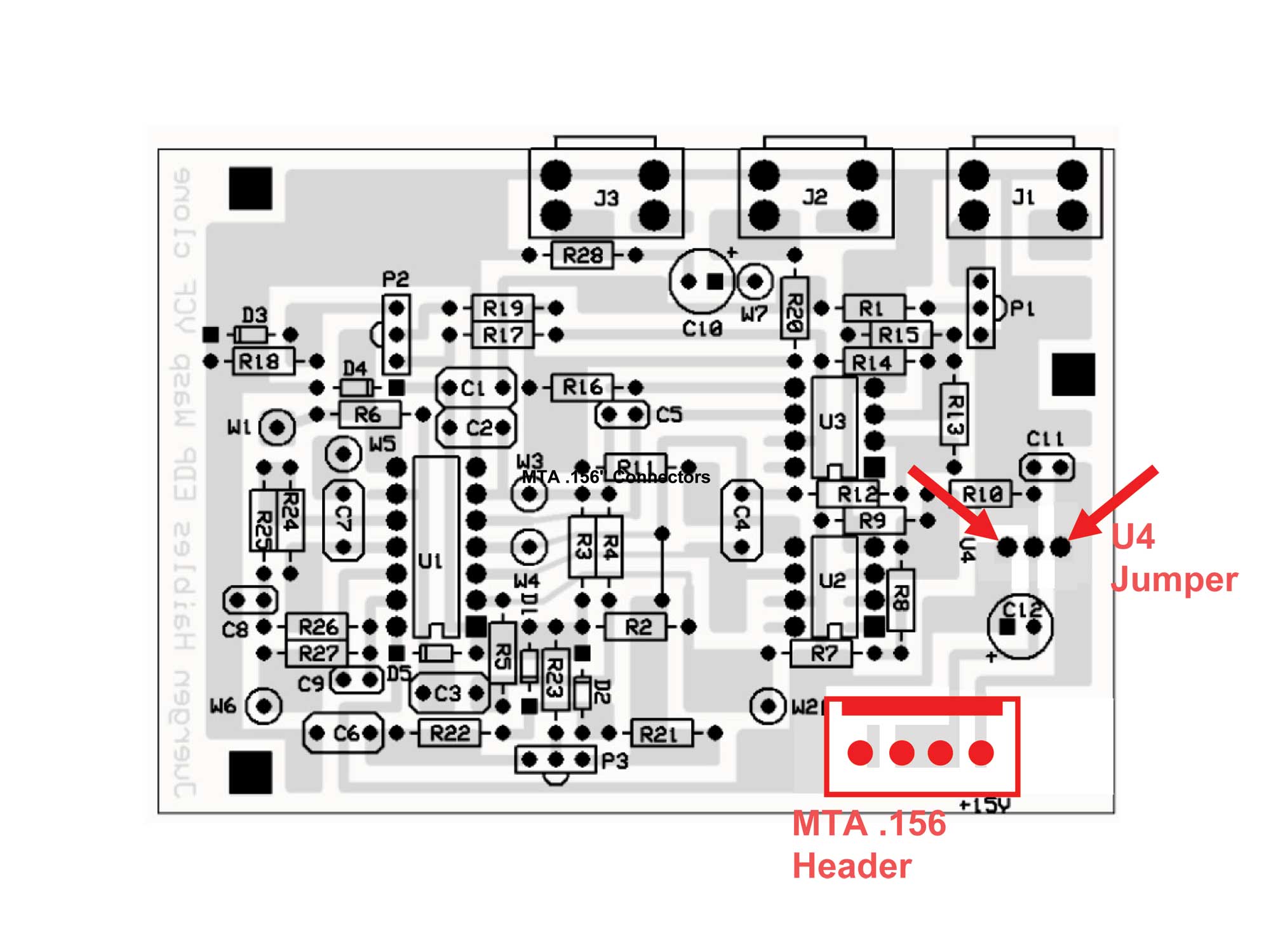
PCB Many thanks go to Matthias for the PCB design, and to Gino for burning us one. Here are Matthias' overlay diagram for the PCB - and the PCB pattern.
Power Matthias has told us that he has run this module on 15 Volts. So we're going to try leaving out the power regulator and putting a jumper across its location:
We'll also drill holes for a four pin MTA .156 header for the power connection. |
Recapitulation of Construction/Feature Options |
Option Details |
Parts |
|
Will and I have developed a parts-list / bill-of-materials in the form of an XL spreadsheet. Jürgen has been very patient and helpful answering our pesky questions. As of today, 9 December, 2010, it's almost complete. Corrections to BOM: None yet - Notes: None yet - Click here to download the spreadsheet (apx. 350K).
|
Panel |
|
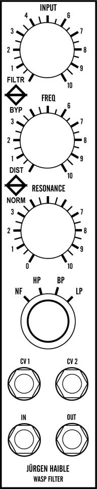
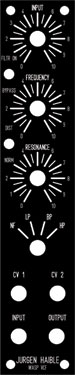
With input from Matthias, Will and I developed the Panel design at the top of the page, reflected in this FPE panel. To download the .fpd file, click here.
|
Construction Phase 1All the stuff in Phase 1 gets soldered using "Organic" Solder. At every break in the action, we wash the board off to get rid of the flux. |
Construction Phase 2All the stuff in Phase 2 gets soldered using "No-Clean" Solder and the PCB doesn't get washed off from here on. |
Set up / Testing |
Use Notes |
|
|


|
The fine Print: Use this site at your own risk. We are self-proclaimed idiots and any use of this site and any materials presented herein should be taken with a grain of Kosher salt. If the info is useful - more's the better. Bill and Will © 2005-2011 all frilling rights reserved
|