Bill and Will's Synth
|
||
Table of Contents |
||
|
This page has become really long, so here's a table of contents that we hope will make it easier to traverse: Background - presents Jurgen's initial description of the phaser Recapitulation of Construction/Feature Options - presents a simple list of the rather varied different possible implementations Option Details - presents all the details of the different possible implementations - you'll need to consider these in deciding how you'll build yours Parts - presents a Bill of Materials and notes about it Panel - presents how we, in collaboration with Jürgen and others, came up with our panels design - ultimately Scott Deyo at Bridechamber fabricated the MOTM format one Construction Phase 1 - Resistors, Capacitors, IC Sockets, Power Plugs, MTA headers Construction Phase 2 - Trimmers, Panel connections |
||
Background |
||
|
Jürgen's posting describes what he did: "I've redesigned the original circuit, such that there are no more exotic components (no more obsolete dual FET), and all the circuitry that originally was potted in the infamous PD-10 modules, is part of the main circuit board in my version. "I plan to make the layout such that you can either
"Also on the board will be the complete power supply (except the mains transformer), and you can either connect a small transformer with 2 * 18V AC secondary voltage, *or* connect a single 18V AC source such as a Wall Wart. "All pots and jacks and LEDs will be connected externally with flexible wires to allow some flexibility on the form factor (19" rack enclosure, or tabletop box, or even an oversized stomp box)."
But Jürgen's posting didn't fully describe the details of the different configurations possible. Here are the different options: |
||
Recapitulation of Construction/Feature Options |
||
|
1. "Ladder" Transistor Array Options Option 1 - Low-cost CA3086 or CA3046 ICs Option 2 - Low-noise SSM2210, MAT-02, or LM394 ICs Option 3 - Hand-matched transistors 2. Tempco Resistor Options Option 1 - Get and use a Temperature Compensated 560 Ohm Resistor at TC5560 Option 2 - Use a Regular 560 Ohm Resistor at TC5560 Option 3 - Temperature Compensated 1K Ohm Resistor at TC5560 - involves changing a resistor and trim POT. 3. Power Supply Options Option 1 - On-board power supply. Option 2 - MOTM-style dual power supply. 4. Connection/Control Options A. Basic Connections (common to all options)
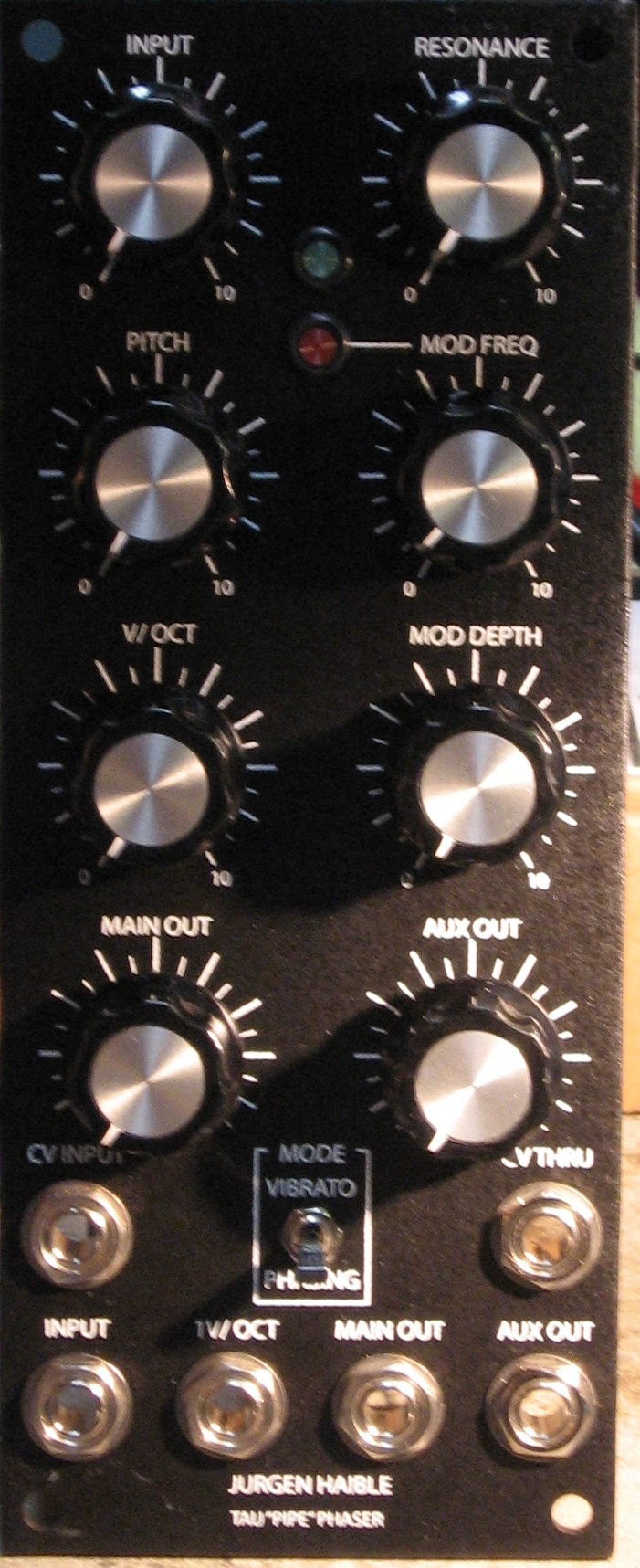
Pitch Knob (Manual Sweep) B. Input/Output Connection Option 1 - Minimal Version - this involves three jacks. Option 2 - Basic Version - this involves three jacks and a POT Option 3 - Deluxe Version - three switches, three jacks, three POTs, two LEDs (red & green) Option 3 Modified - Deluxe version w/o bypass, w/o mode switches, w single LED (the panel above is based on this modified version) - three jacks, three POTs, two LEDs - note: the panel design we created and is offered by Scott Deyo of Bridechamber has one LED hole (where the red one is shown above) C. Phasing/Vibrato Control Option 1 - Hard Wired - involves hard wiring or jumpers on the PCB. Option 2 - Switched - involves one switch. D. Volt per Octave CV Input Option 1 - Without Panel Tuning - involves just the Control Voltage Input Jack. Option 2 - With Panel Tuning - involves the Control Voltage Input Jack and a tuning control POT.
Option 3 (Superseded) - E. Modulation CV Input / Output Option 1 - Without Modulation CV - involves a jumper on the PCB. Option 2 - With Modulation CV Input/Output - involves two jacks. 5. Panel Designs |
||
Option Details |
||
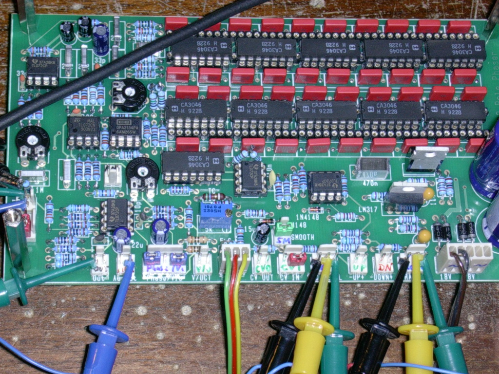
1. "Ladder"Option 1 Jürgen designed the PCB so you can implement the "ladder" three ways. This illustrates the first option - as he said - "use cheap CA3086 transistor arrays." Actually, he used CA3046s... he says they're somewhat better.
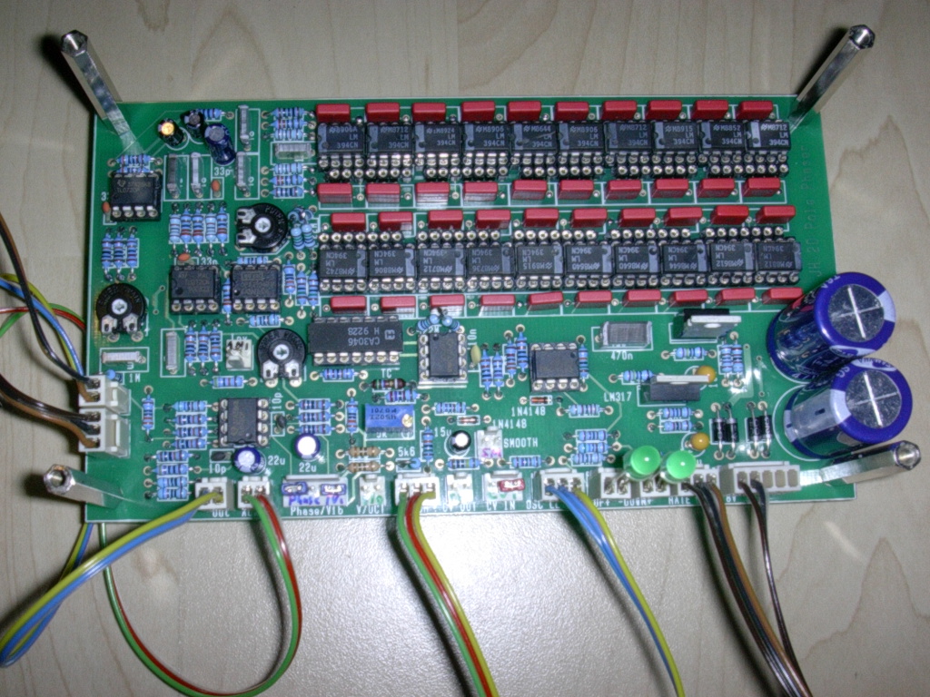
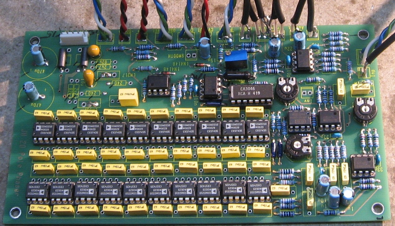
Option 2 This illustrates the second option "for an ultra low noise version - SSM2210, MAT-02, LM394 (expensive! 20 pairs needed!)."
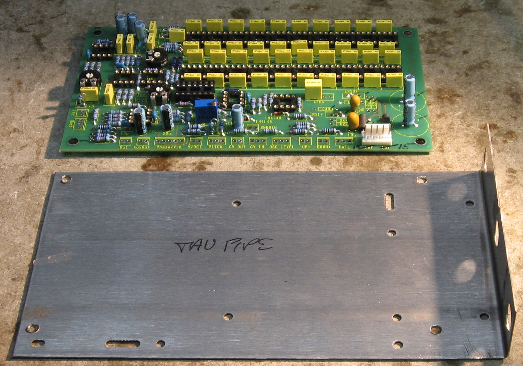
Option 3 This is the matching transistor option—there's no illustration for this one. If someone has information on how you would go about matching the transistors, etc. we'd love to hear it. 2. Tempco ResistorIn his implementation of the Tau Pipe, Jürgen used a Tempco (Temperature Compensated) 560Ohm Resistor at location TC560.
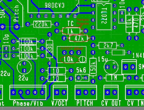
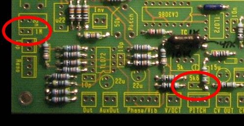
We had a hard time finding a TC560 Resistor. So we asked what our options are. Jürgen told us that we could implement with a regular old 560 Resistor, but he also said: "The tracking to a 1V/Oct CV can be adjusted, but this adjustment will only be precise at one temperature. With the tempco resistor, ideally the adjustment will be as good at room temperature as at other temperatures. In practice, it's just an approximation. And, a phaser is a kind of *filter*, not an oscillator, so precise tracking is not that crucial." But he came up with a third possibility - to use a 1K tempco - and adjust a couple other things to compensate. Option 1 Get and use a Temperature Compensated 560 Ohm Resistor at TC5560 Option 2 Use a Regular 560 Ohm Resistor at TC5560 Option 3 Temperature Compensated 1K Ohm Resistor at TC5560 - inwhich case the 27K resistor gets changed to 47K - the 5K trim POT changes to a 10K trim POT. This diagram of Jürgen's shows this option.
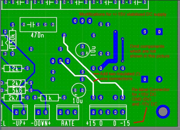
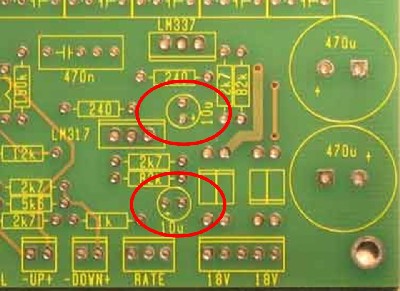
3. Power SupplyOption 1 On-board power supply - per Jürgen, "...creates stabilized positive and negative voltages (+15V and -15V) from a 18V AC voltage." Option 2 MOTM-style dual power supply. We can't say it better - and this is important so we glommed this off Jürgen's site... here's what he says: "...if you want to integrate the board into a Modular System like MOTM or others, which already have a +/-15V Dual Supply voltage available, you can modify the Phaser Boards to use this directly. In fact, you don't need a lot of components - you just omit them on the board. (Do not use the Phaser on a +/-15V supply with these components soldered in! This will result in severe damage of the Phaser, or the Modular synth, or both!) "On a Board without these components, solder two wire connections (use insulated wire!), as shown in this picture. Re-label the 18V AC connector for the use of +15V and -15V. (glue some tape over the original silkscreen, to avoid confusion, and severe damage from wrong connections.)
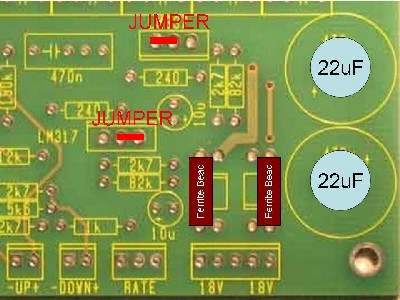
"I know these questions will come, so I tell you right now: There is no standard power connector provided for ony of the commercial modular systems - you have to connect some wires directly, or build an adapter. "Other voltages, like +/-12V, are not supported. (You can try to run the modified board on +/-12V, and report the results back to me if you like; I expect it to work somehow, but the sweep range will most probably not be right. The 1/x function generator is tricky here!)" Option 2 á la Will MOTM-style dual power supply per Jürgen's notes, but with axial ferrite beads and caps like standard MOTM modules. Later on, as we were working on the PCB, Will was comparing Jürgen's option 2 (above) with the power supply circuits typically found on MOTM modules and asked Jürgen about the following alternative 15V supply. Jürgen said the 22μ caps wouldn't hurt and the ferrite beads are a good idea and called the implementation "elegant" - so this is how we'll build it. You can just leave out the 22μ caps and the beads and jumpers still should work fine. Anybody want to double-check Will's idea? Drop us a note.
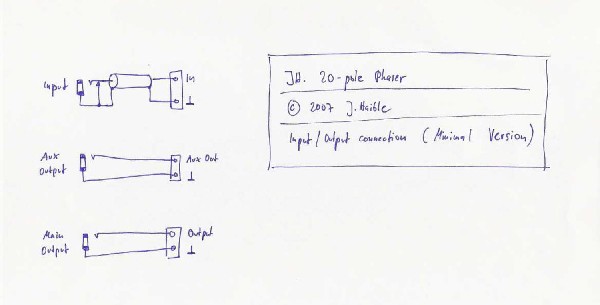
It is vital to note that, at the header, the positive and negative poles are reversed compared to standard MOTM connections. We'll solder in a five-pin header here and make a special power cable for the module that takes this into account! 4. Connections and ControlsA. Basic ControlsPitch Knob (Manual Sweep) 100k Linear - to "pitch" on PCB Resonance Knob (Feedback) 100k Linear - to "reso" on PCB LFO Rate Knob (Modulation Frequency) 100k Linear - to "rate" on PCB Oscillator Level Knob (Modulation Depth) 10k Log - to "osc_level" on PCB B. Input/Output ConnectionA note about jacks - Jurgen's drwaings show 111A (2 conductor open tip) type jacks in some cases. It looks to us like Synth Tech Modules always use 112As (2 conductor closed tip) and just don't make use of the extra connector when no needed. We're showing the 111As here in our list, but we're going to use all 112As in our build. Option 1 Minimal Version - this involves three jacks: Input Jack 2 Conductor Closed Tip Enclosed 1/4" Phone Jack (112A type) Aux Out Jack 2 Conductor Open Tip Enclosed 1/4" Phone Jack (111A type) Main Out Jack 2 Conductor Open Tip Enclosed 1/4" Phone Jack (111A type)
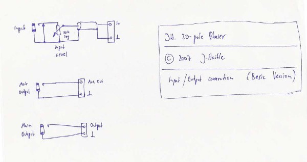
JH's diagramOption 2 Basic Version - this involves three jacks and a POT: Input Jack 2 Conductor Closed Tip Enclosed 1/4" Phone Jack (112A type) Input level potentiometer 10k Log - to "osc_level" on PCB Aux Out Jack 2 Conductor Open Tip Enclosed 1/4" Phone Jack (111A type) Main Out Jack 2 Conductor Open Tip Enclosed 1/4" Phone Jack (111A type)
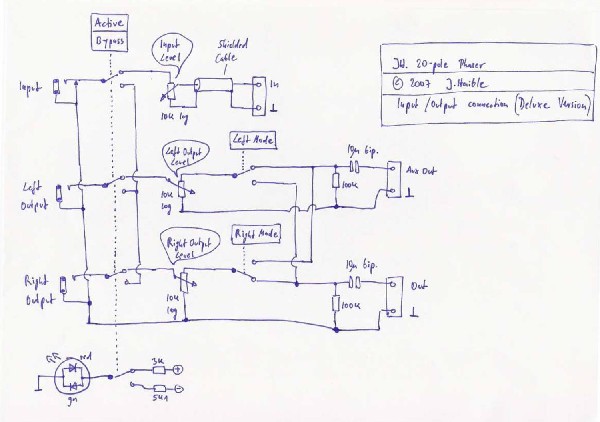
JH's diagram Option 3 Deluxe Version - woah baby! Active/Bypass Switch 4 pole double throw switch - bat lever (flat lever unavailable) LEDs - (Assuming panel implemented without dual color LEDs) Red Green Input Jack 2 Conductor Closed Tip Enclosed 1/4" Phone Jack (112A type) Input level potentiometer 10k Log - to "osc_level" on PCB Left Out Jack 2 Conductor Open Tip Enclosed 1/4" Phone Jack (111A type) Left Out level potentiometer 10k Log - to "left mode" switch and "aux_out" ground on PCB Left "Mode" Switch 1 pole double throw switch - flat lever Right Out Jack 2 Conductor Open Tip Enclosed 1/4" Phone Jack (111A type) Right Out level potentiometer 10k Log - to "right mode" switch and "out" ground on PCB Right "Mode" Switch 1 pole double throw switch - flat lever
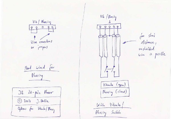
JH's diagram Option 3 Modified Modified Deluxe Version (this is what the face-plate (top of page is designed to accommodate - except if you want two LEDs like us, you have to drill an extra hole.) Red (and green) LED Input Jack 2 Conductor Closed Tip Enclosed 1/4" Phone Jack (112A type) Input level potentiometer 10k Log - to "osc_level" on PCB Main Out Jack 2 Conductor Open Tip Enclosed 1/4" Phone Jack (112A type) Main Out level potentiometer 10k Log - to "left mode" switch and "aux_out" ground on PCB Aux Out Jack 2 Conductor Open Tip Enclosed 1/4" Phone Jack (111A type) Aux Out level potentiometer 10k Log - to "right mode" switch and "out" ground on PCB C. Phasing/Vibrato ControlOption 1 Hard Wired - involves hard wiring or jumpers on the PCB. Option 2 Switched - involves one switch. Vibrato/Phasing Switch 2 pole double throw switch - flat lever
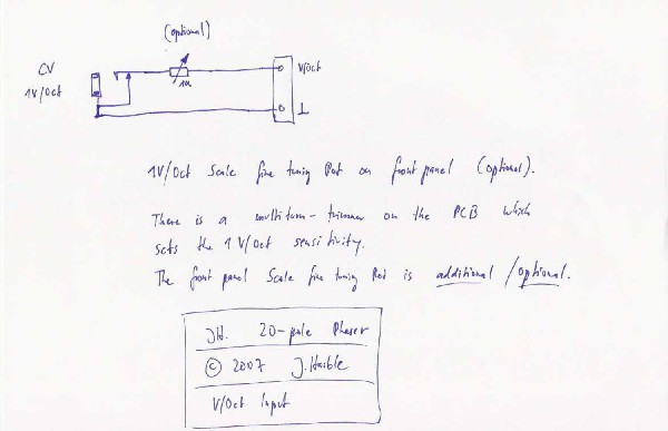
JH's diagram D. Volt per Octave CV InputOption 1 Without Panel Tuning - involves just the Control Voltage Input Jack. V/Oct Jack 2 Conductor Closed Tip Enclosed 1/4" Phone Jack (112A type) Option 2 With Panel Tuning - involves the Control Voltage Input Jack and a tuning control POT. V/Oct Jack 2 Conductor Closed Tip Enclosed 1/4" Phone Jack (112A type) V/Oct Tuning Potentiometer 1K - to "jack tip" and "V/oct" on PCB
JH's diagram Option 3 (Bill and Will's) mrmike from the MOTM list pointed out that this option is really unnecessary - the switch is accomplished by the jack in option 2.
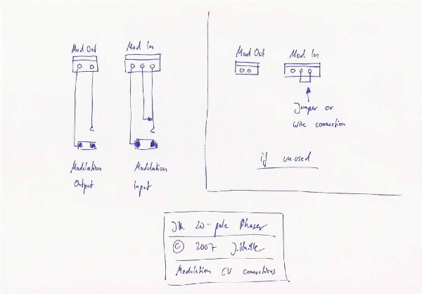
E. Modulation CV Input / OutputOption 1 Without Modulation CV - involves a jumper on the PCB. Option 2 With Modulation CV Input/Output - involves two jacks. Modulation Input Jack 2 Conductor Closed Tip Enclosed 1/4" Phone Jack (112A type) Modulation Output Jack 2 Conductor Open Tip Enclosed 1/4" Phone Jack (111A type)
JH's diagram |
||
Parts |
||
|
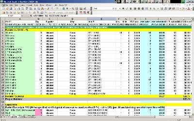
Will and I have developed a parts-list / bill-of-materials in the form of an XL spreadsheet. Jürgen has been very patient and helpful answering our many pesky questions. As of today, 7 August 2007, it's not complete yet - and thanks to very kind users, we're weeding out the mistakes - so please don't take it as gospel. Even so, just now we've used it to make our Mouser, Allied Electronics, Webtronics (CA3046s), and Bridechamber (SSM2210s) purchases and we are relatively confident in our specifications. In the BOM, the left-most column is the "part." The parts we've ordered have a green background. These parts we have a high (but not perfect) level of confidence that we've specified correctly - we caught a mistake or two in part numbers / prices as we were ordering. please double-check us and let us know of mistakes you find. Jürgen just sent us a link to his BOM (you can find it on his site here) and we've begun cross-referencing it. As we match it up, we're coloring the background of the Qty column pink. Corrections to BOM: Right off the bat we noticed we'd missed the SMD 0805 100nF capacitors he had on the solder side of the PCB. We couldn't see these in his pics, of course—so we'd missed them. We included them in the BOM just now. We asked Jürgen to double-check our specification and he says they're the right thing. Thanks so much, Jürgen! 25 July—Ingo caught a discrepancy in the number of resistors needed —off by one 10k Ohm and one 10 Ohm—corrected now. Thanks Ingo! 6 August—Romeo notes we've mis-specified the 5K (and therefore the 10K) trimmer - we got the pin spacing wrong. We've made the correction to the BOM. Sorry about that, folks. We're going to have to re-order that part as well. Thanks Romeo! 7 August—our own construction has begun and so we're finding mistakes—we needed six 3.3k resistors, not five. We've updated the BOM. 9 August - Today Hans points out that we specified a 100K ohm trimmer - it should be a 100 ohm trimmer. We've corrected it. Thanks, Hans. Notes: There are two blue-colored columns named "min order" and "min extended." These are intended to indicate what someone would have to minimally order to build the Tau Pipe—but with all the controls. That's just for cost estimating. The next couple columns over is what Will and I are planning to order. We always order extras to build up our stock of parts. The BOM doesn't have the PCB mounting hardware and faceplate included yet. That's next. We had a great experience ordering from Bridechamber - . Click here to download the spreadsheet (apx. 350K).
|
||
Panel |
||
|
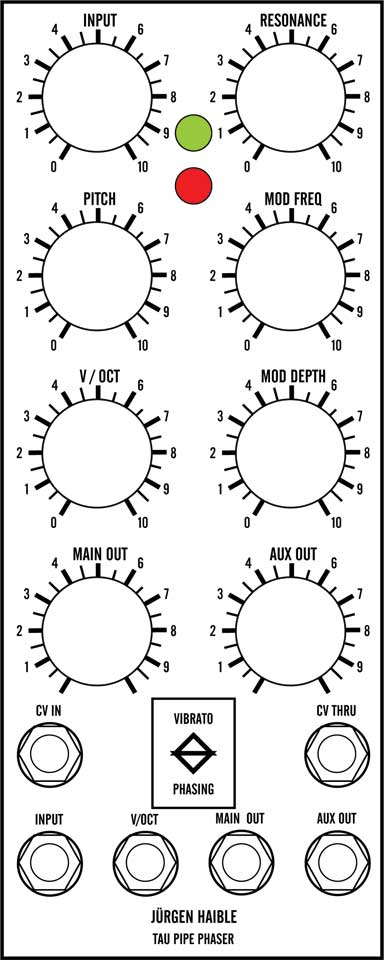
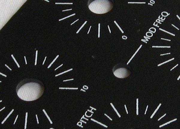
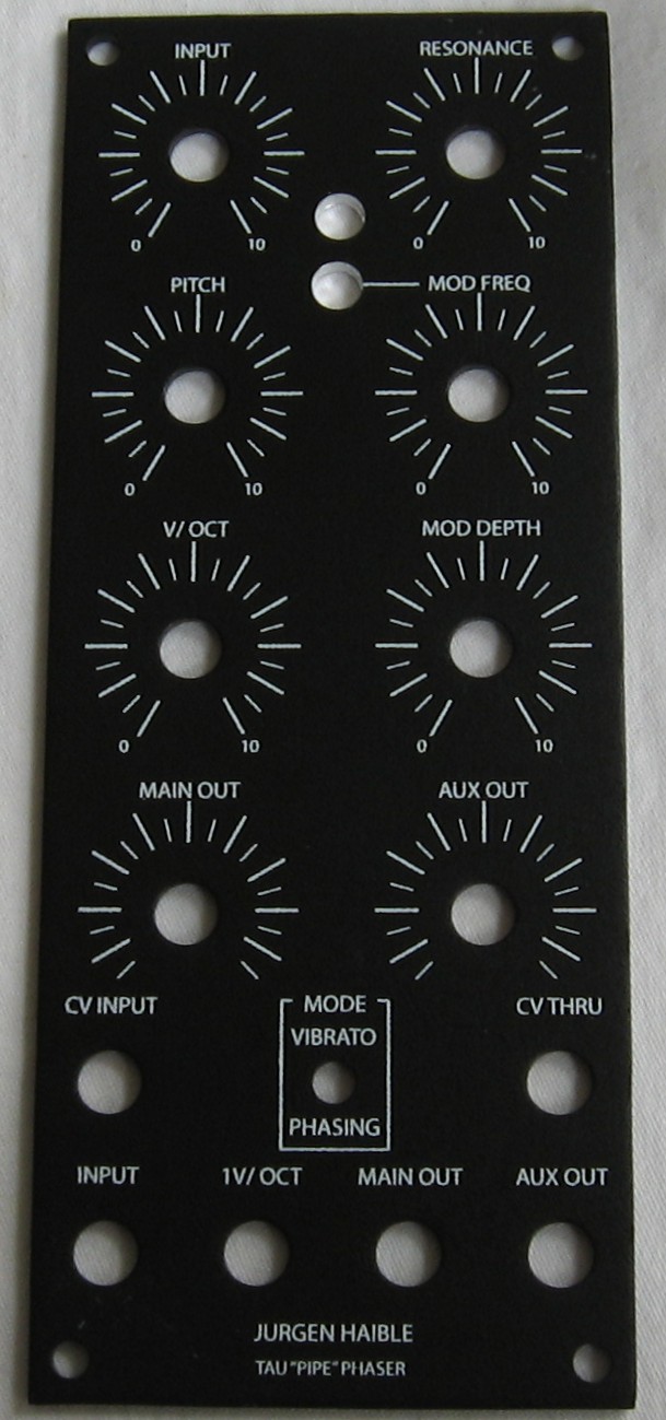
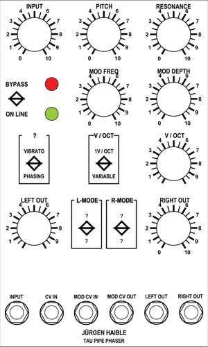
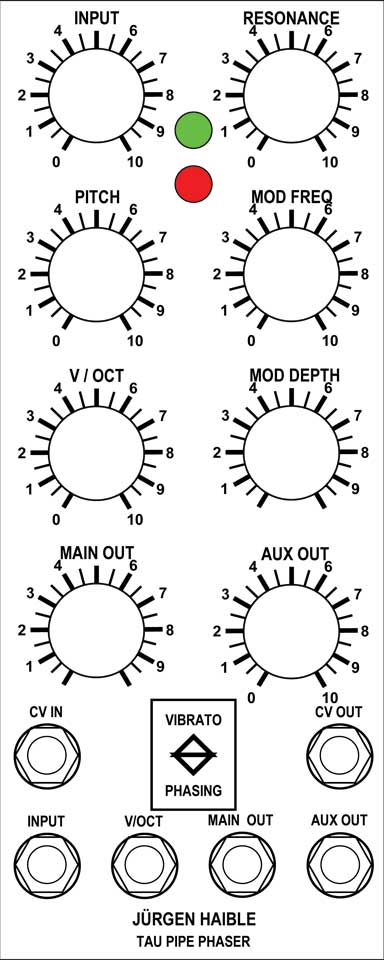
With the help of Jürgen and in collaboration with Mike (mrmike) and with input from Scott Deyo (Bridechamber.com), Will and I developed the Panel design at the top of the page. If you click on that drawing, you can see a bigger version. Scott Deyo at Bridechamber dutifully made up panels just like this and to accommodate more options, he made the LED hole 1/4in diameter rather than the 5/16in we need (because we're going to use the MOTM-standard-sized LEDs). Also, our design presumed the use of a dual color LED. Apparently we misunderstood when we did the design. Now - we could build the module with just one LED, but we'd like to have two like Jurgen's design calls for. So we drilled an extra hole. |
||
|
Panel Modification |
||
|
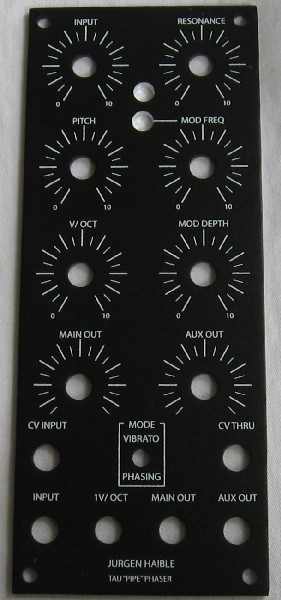
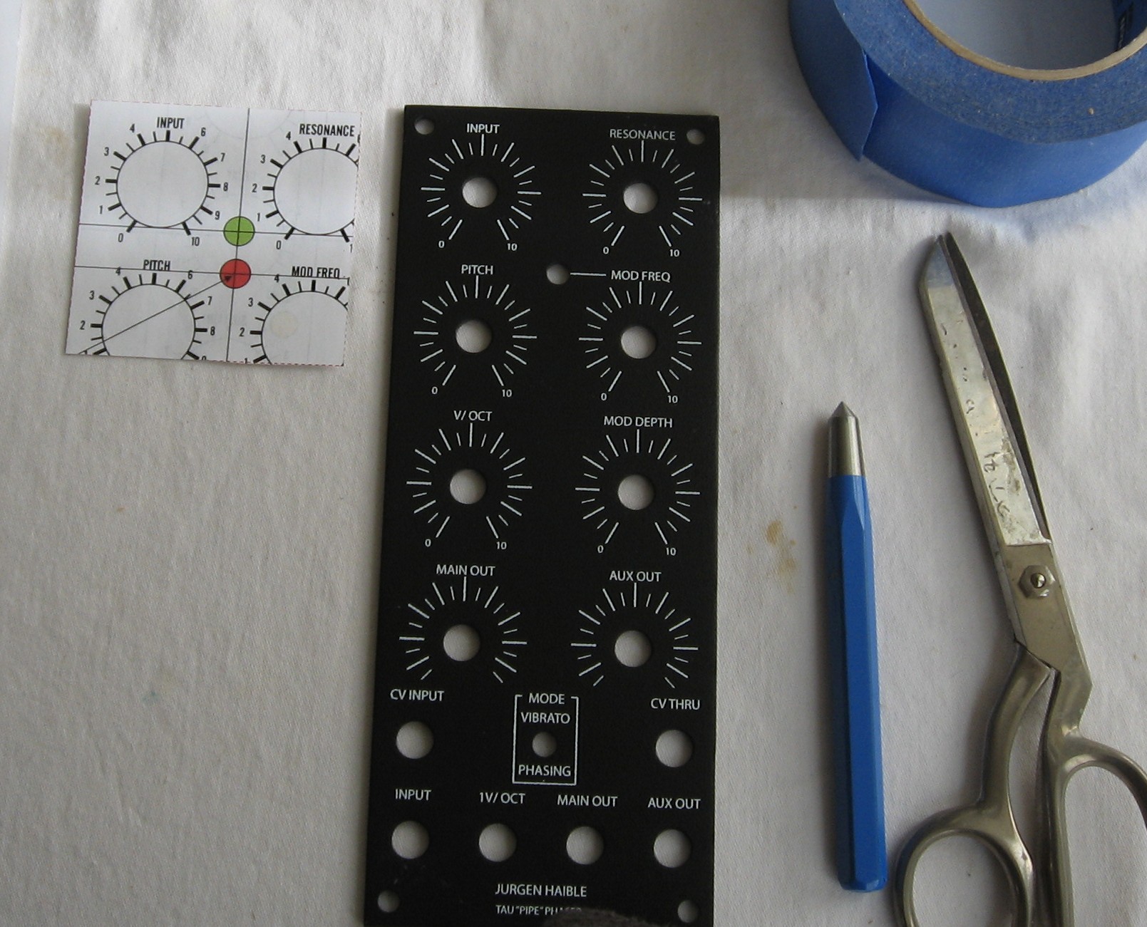
We got our panel from Bridechamber:
OK - so here's the panel design with both LEDs:
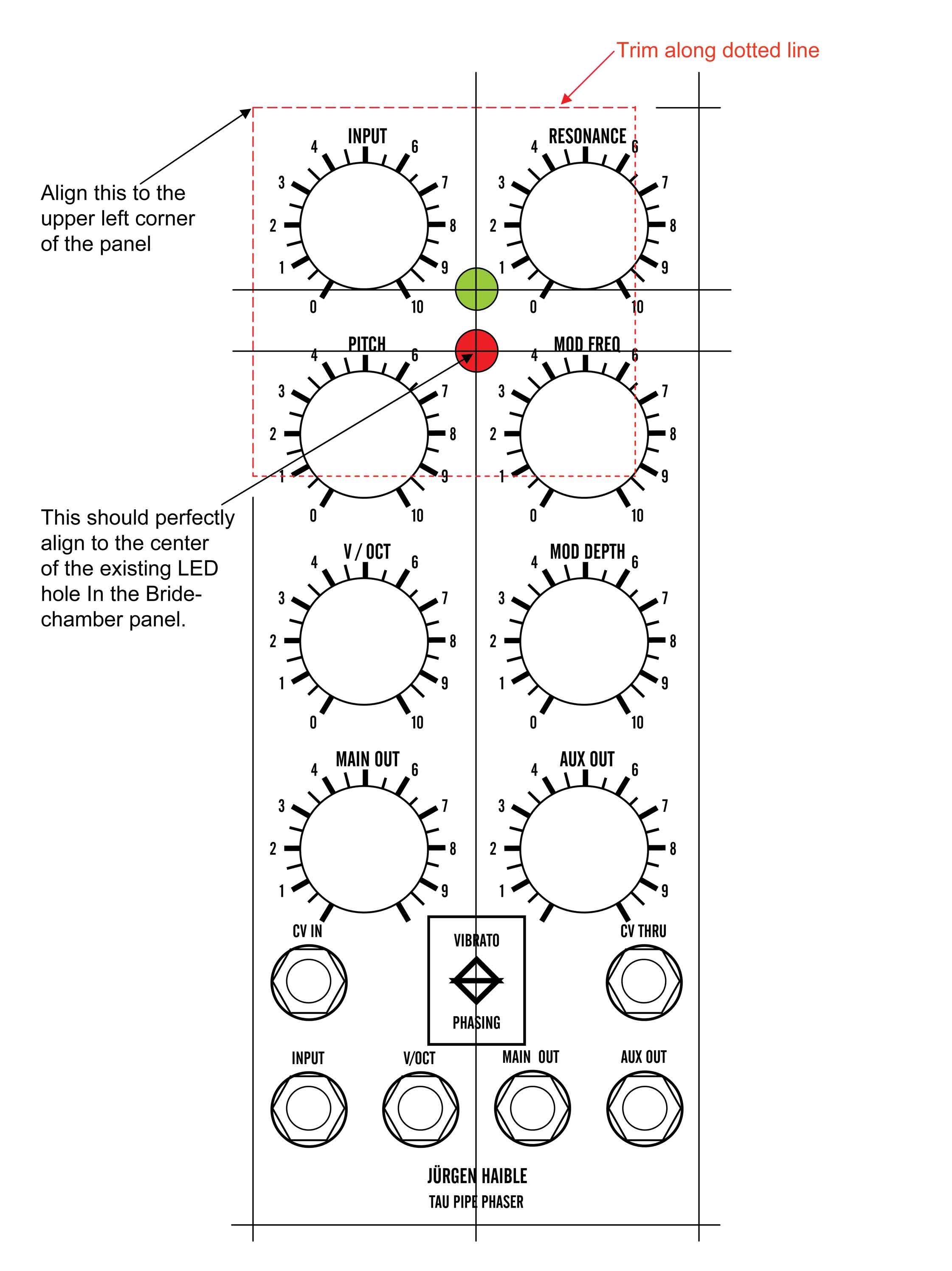
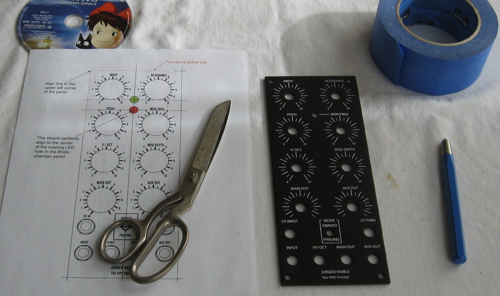
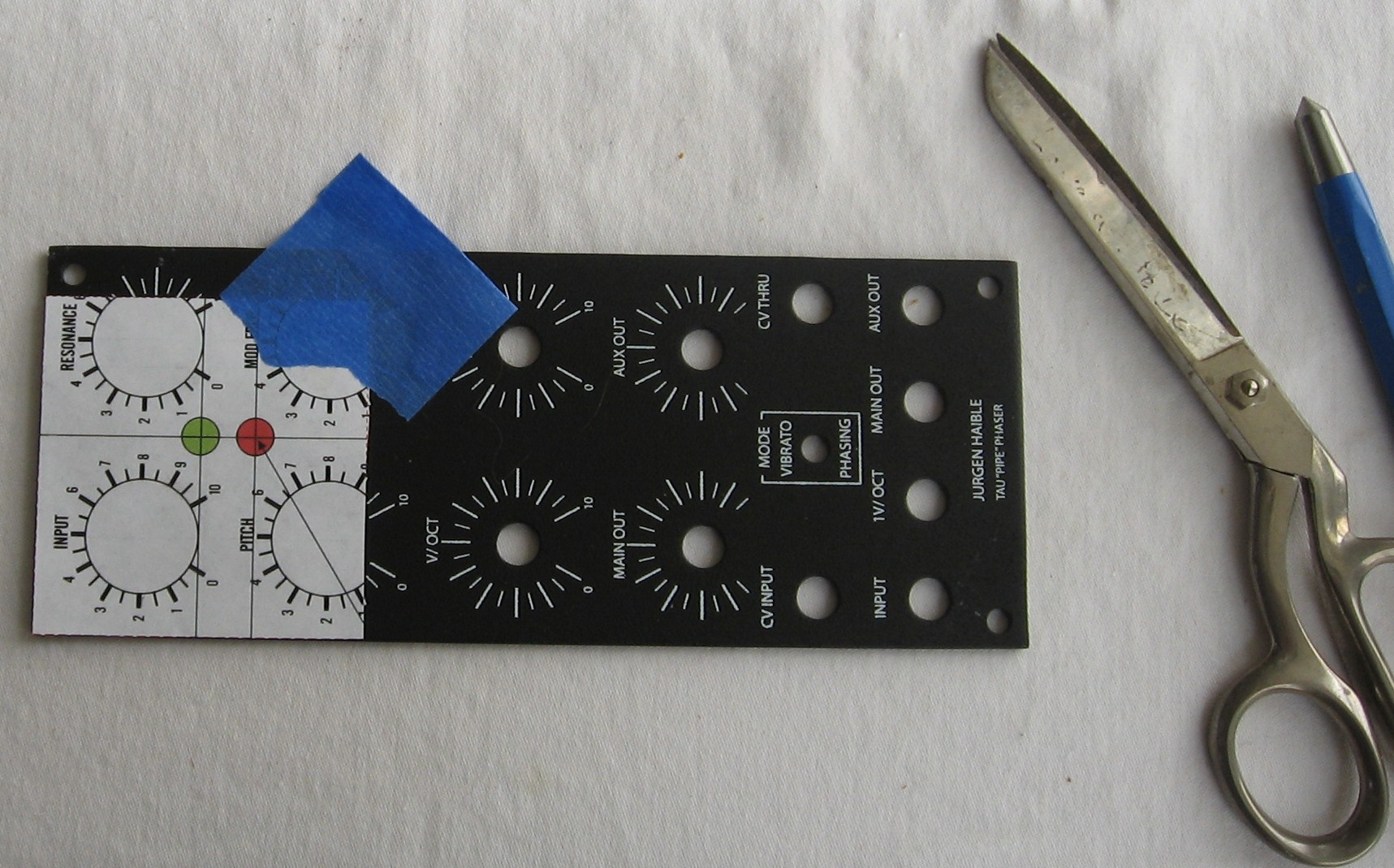
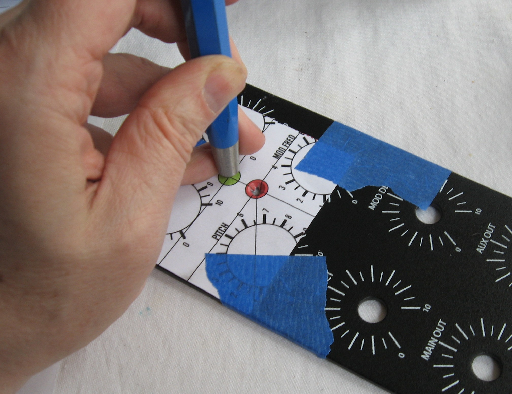
Like our work on the MOTM 800 panel, we're going to use a paper template we designed with Powerpoint that we'll attach to the panel to show us where the holes should be. When printed on our printer, the template design prints out on an 8" x 11" piece of paper such that the distances between Pot holes and the width of the panel work out perfectly. And so by cutting out the template and taping it to the panel, the center lines for the LED holes wind up in the exact right spot. Click here to download the Powerpoint file which has both front and rear templates.
Now - we got so involved in drilling, that we didn't take pictures of the process. But here's what we did:
|
||
|
August 2007 - |
||
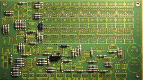
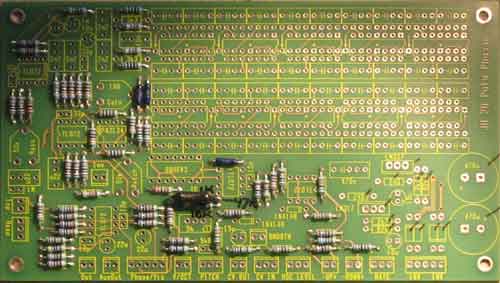
Construction Phase 1All the stuff in Phase 1 gets soldered using "Organic" Solder. At every break in the action, we wash the board off to get rid of the flux. |
||
|
|
||
|
Resistors |
||
|
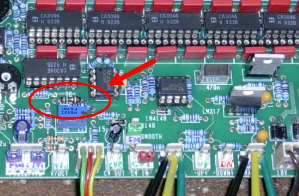
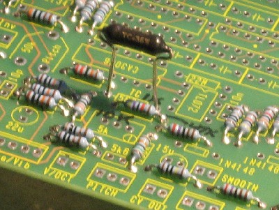
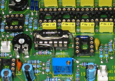
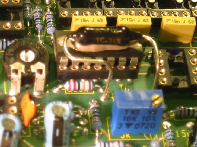
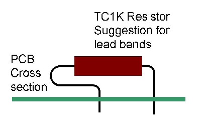
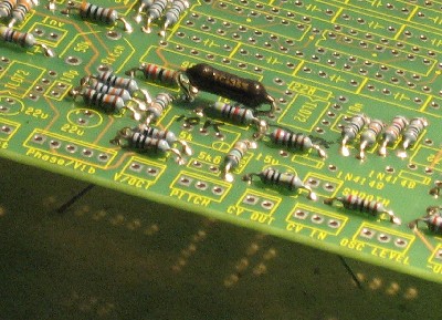
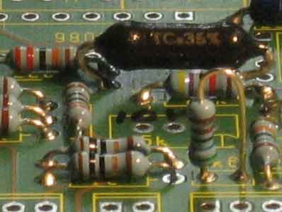
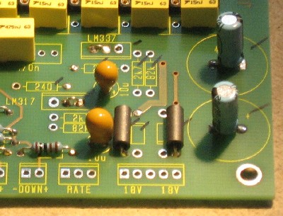
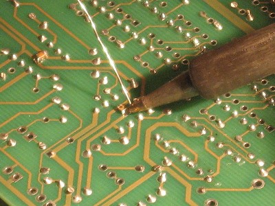
In the process of soldering in the resistors, it came time for the Temperature Compensated 1K. It was after we'd soldered ours in, that we realized the proper installation of a tempco resistor includes using some "heat transfer compound." We asked Jurgen about it, and he wrote: "If you want to have the best compensation, the tempco reistor should have thermal contact with the nearby CA3086 (or 3046). Before soldering it in, place the resistor body on top of the IC, then bend the (long) wires towards the holes in the pcb, and solder them in. If you're doing this, you can further improove thermal contact by applying heat transfer compond between the resistor and the IC. Or you could glue the resistor down on the IC. But it's all not so important, as it's not a VCO. I simply have my tempco resistor soldered in with short wires on my board." OK—so this sounds like good news—this is how we did it because we didn't know any better. One of the options, after all, is to not use a tempco at all.
We'll forgo the heat transfer compound. But if you are going to do it right and stretch the tempco over the CA3086 (or 3046), here's how James Elliott did it—thanks James!
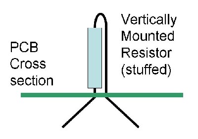
James Elliott "In order to ensure that I get the job right the first time I had to get a general idea as to what I needed to do, I figured that the best way of doing this was to simply center the tempco over the CA3086... The first thing I noticed was that I needed to make two types of bends for each lead. The first type of bend would take the leads parallel over the board with the intent of lining them up OVER their holes (Horizontal Bends). The second type of bend would take the leads adjacent to the board and INTO their holes (Vertical Bends). "After taking these mental notes, I was prepared to take action... Horizontal Bends: 1) I needed to make one 90 degree bend on the lead closest to the power supply (Lead A) to align it over its hole. I made this bend about 1/4 inch from the BODY of the tempco. 2) The lead next to the 50K trimpot (Lead B) would need two 90 degree bends to align it over its hole. a) The first bend was made in the same direction of the horizontal bend on Lead A, about 1/8 inch from the BODY of the tempco. b) The second bend was made about 1/4 down the lead, made on the same horizontal plane as the first bend. This bend took Lead B back toward the Lead A. 3) After making these 3 bends the tempco resembled the shape of a lowercase Q (q) when looking down on it. Vertical Bends: 1) Both leads only required one bend each a) Lead A was bent downwards at a 90 degree angle where Lead B intersected over/under it b) Lead B was bent downwards at a 90 degree angle at about the halfway point along the BODY of the tempco 2) At this point both leads were once again parallel with each other facing down towards the holes. Installation: 1) I applied thermal grease (Arctic Silver 5) down center of the CA3086, lengthwise 2) I applied solder in one of the resistor holes (to help hold the tempco in place while attempting the installation) 3) While applying heat to the soldered hole, I inserted the leads into their respective holes 4) While the solder was still liquefied, I pressed the tempco firmly on top of the CA3086, directly into the thermal grease. 5) Once the tempco was in place I removed the soldering iron from the soldered hole, while continuing to press the tempco against the CA3086. 6) Once the solder hardened, I soldered the other lead in place. 7) Once the solder from the second lead hardened, I touched up the first lead with some more solder "That was it - pretty easy, with no problems and no mess." - James Elliott
James Elliott Superb, James! So - If you're not going to try to stretch the tempco way over that CA3086 like Jurgen says is ideal, but solder it directly in—like he says he did, and like we did 'cause we didn't know better—we figured out that bending the leads like this would have given more room for that Tl072 next to it. Just something another builder might consider.
As usual with us, whereas we are vigilant about orienting all the resistors, caps, etc. consistently so their values can be read easily (in case we need to trouble-shoot them later), we oriented the resistors with the "Tolerance" stripe on the left (relative to the text on the pcb). Why did we do it this way? Well - 'cause the 5% gold stripe is so pretty and easy to see (of course)... and so we put it on the left - well - just because - and now we want to ramain consistent with our other modules. You might want to do it the opposite way. (For the table of resistor value markings click here.) |
||
|
Capacitors |
||
|
But then Will cooked up the alternate 15V power implementation:
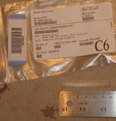
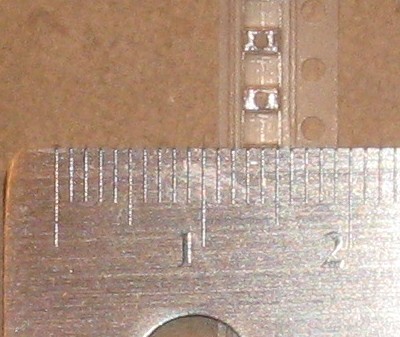
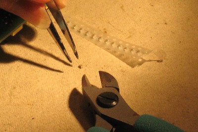
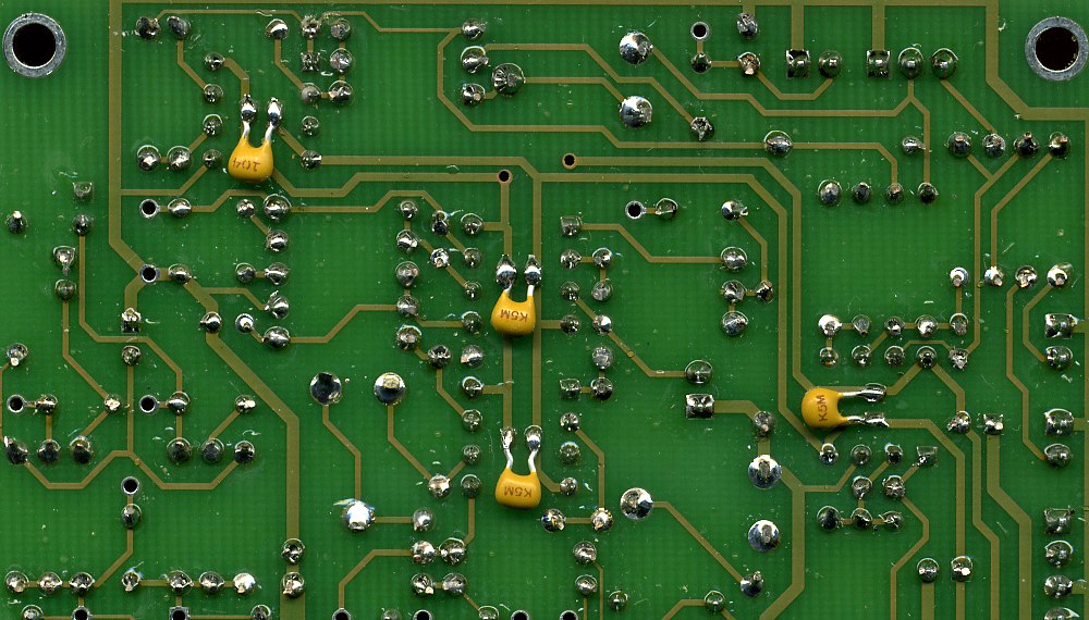
September 2007 - And now for those crazy .1μF SMD Ceramic Chip Capacitors: (Yves Usson suggested an alternate implementation using regular small ceramic caps - click here)
And we got this great tip from Jason: "Hi again - I've spent some time working on my tau pipe today and wanted to give you a tip. I've never soldered any SMD stuff, so the caps on the backside of the board were frustrating. After the second one I realized wetting one of the two pads with a *tiny* bit of solder allows you to drag and drop the cap into place. Then you just touch the soldering tip to the pad and it draws the cap down to the hot solder. At this point you can easily solder the other side. I used an exacto to make adjustments while heating the solder and adjusting the position. The last four went really quickly! "Just a tip, in case you haven't had to deal with such small items also... "Jason"
|
||
|
IC Sockets - Power Plugs |
||
|
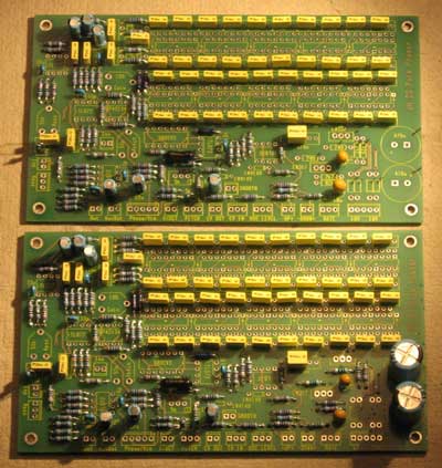
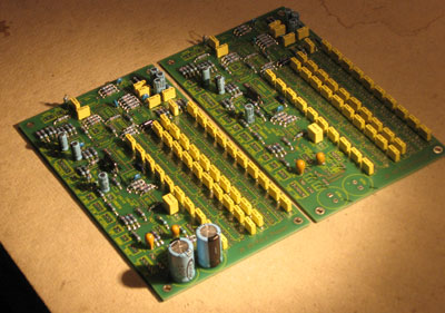
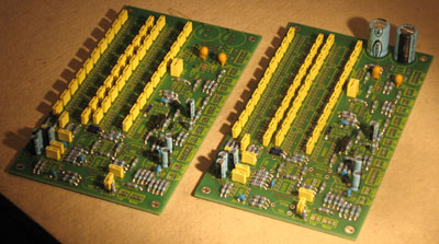
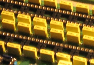
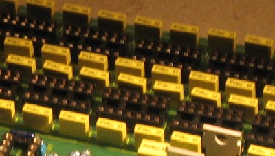
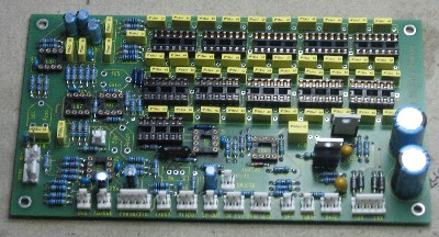
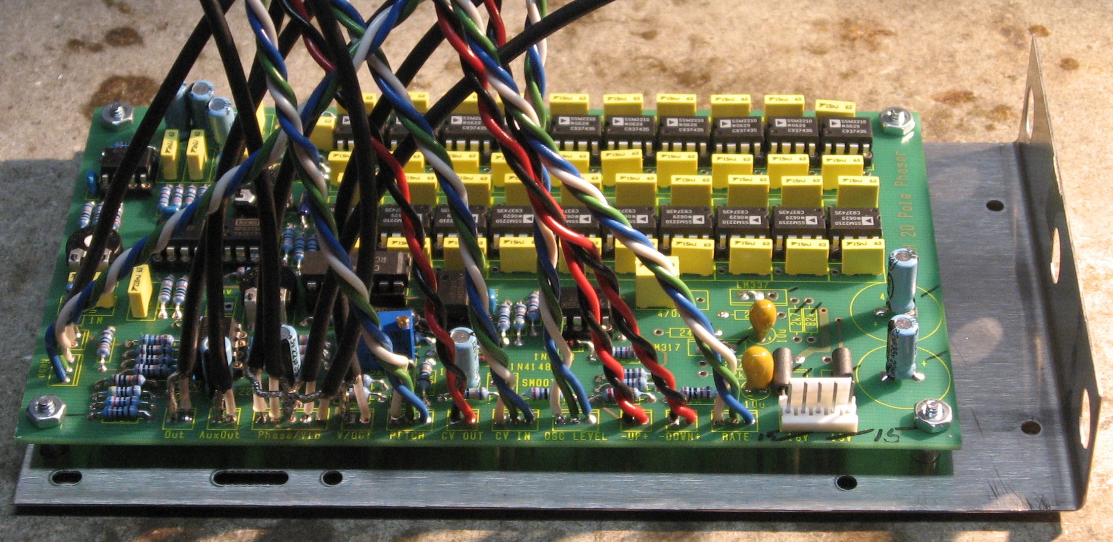
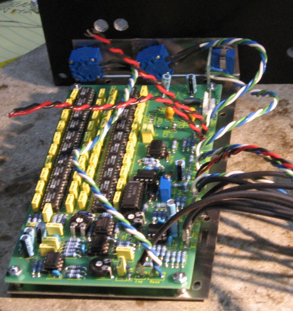
Remember - we're building two versions of the Phaser. In one - the one for our Synth - we're using twenty high-quality very low noise 8-pin SSM2210 ICs. So we'll need 8-pin IC sockets for these.
In the other - the one for Bills guitar rack, we're using ten 14-pin CA3046 ICs. And so we'll need 14-pin IC sockets for these.
Both versions have the other IC sockets in common and also both have the Power MTA Connector power plugs in common.
|
||
|
MTA Connectors |
||
|
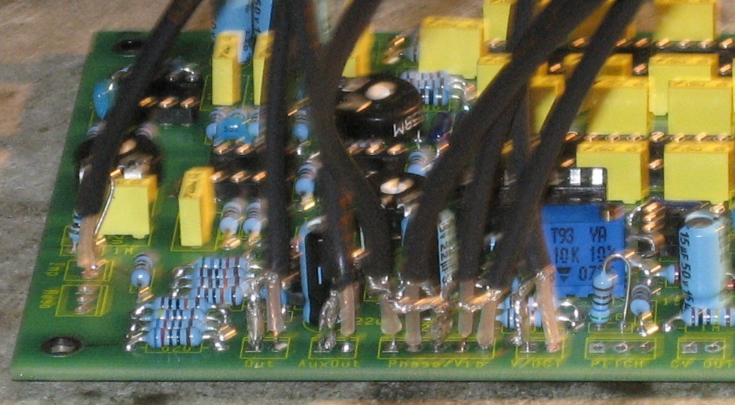
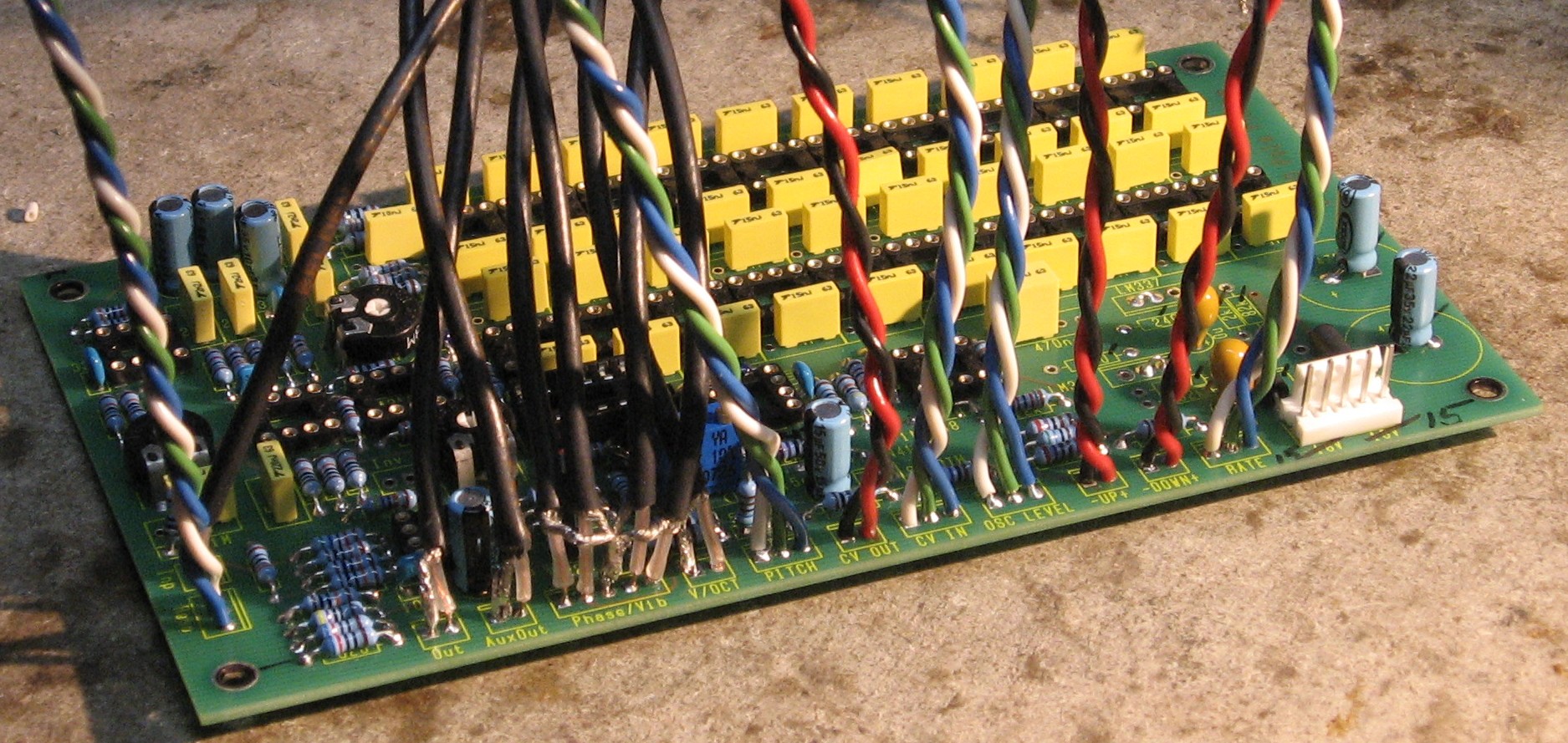
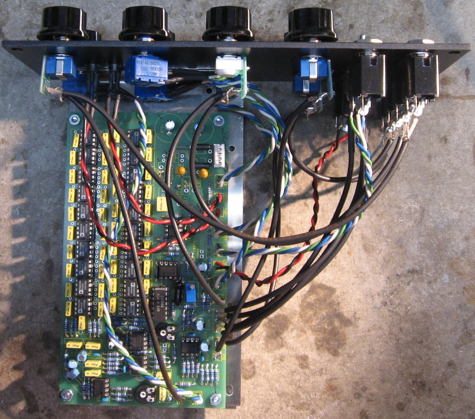
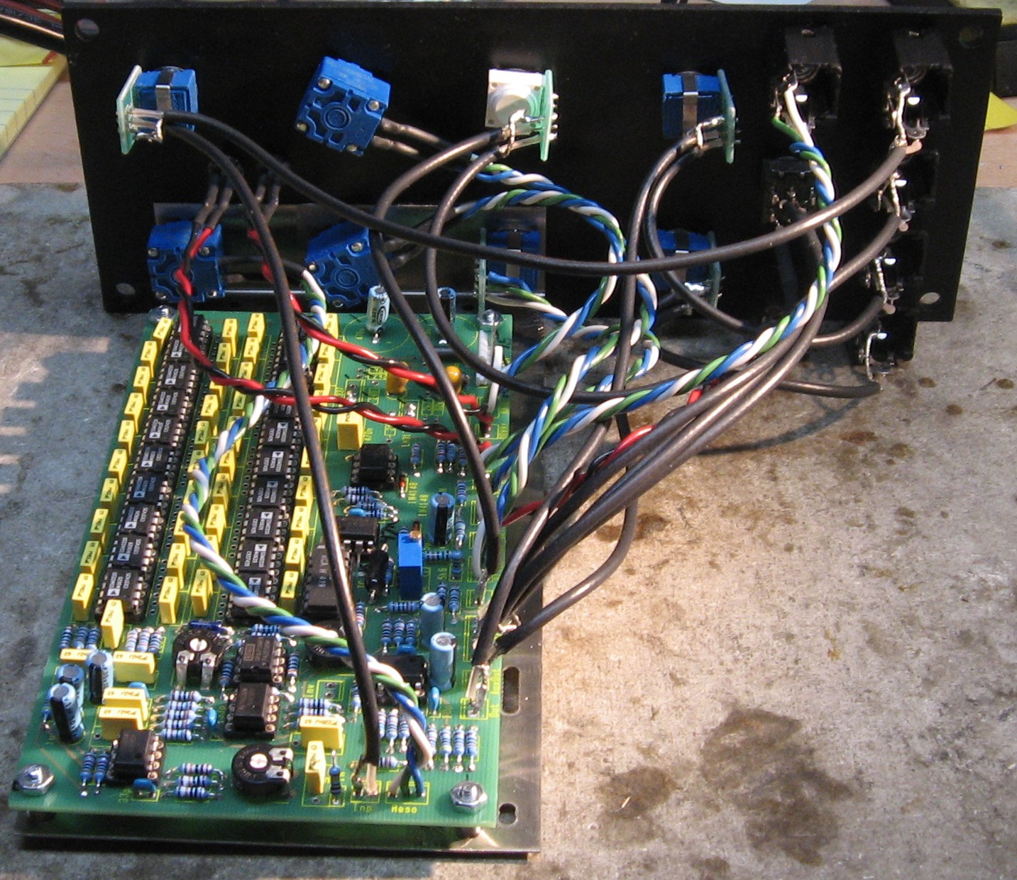
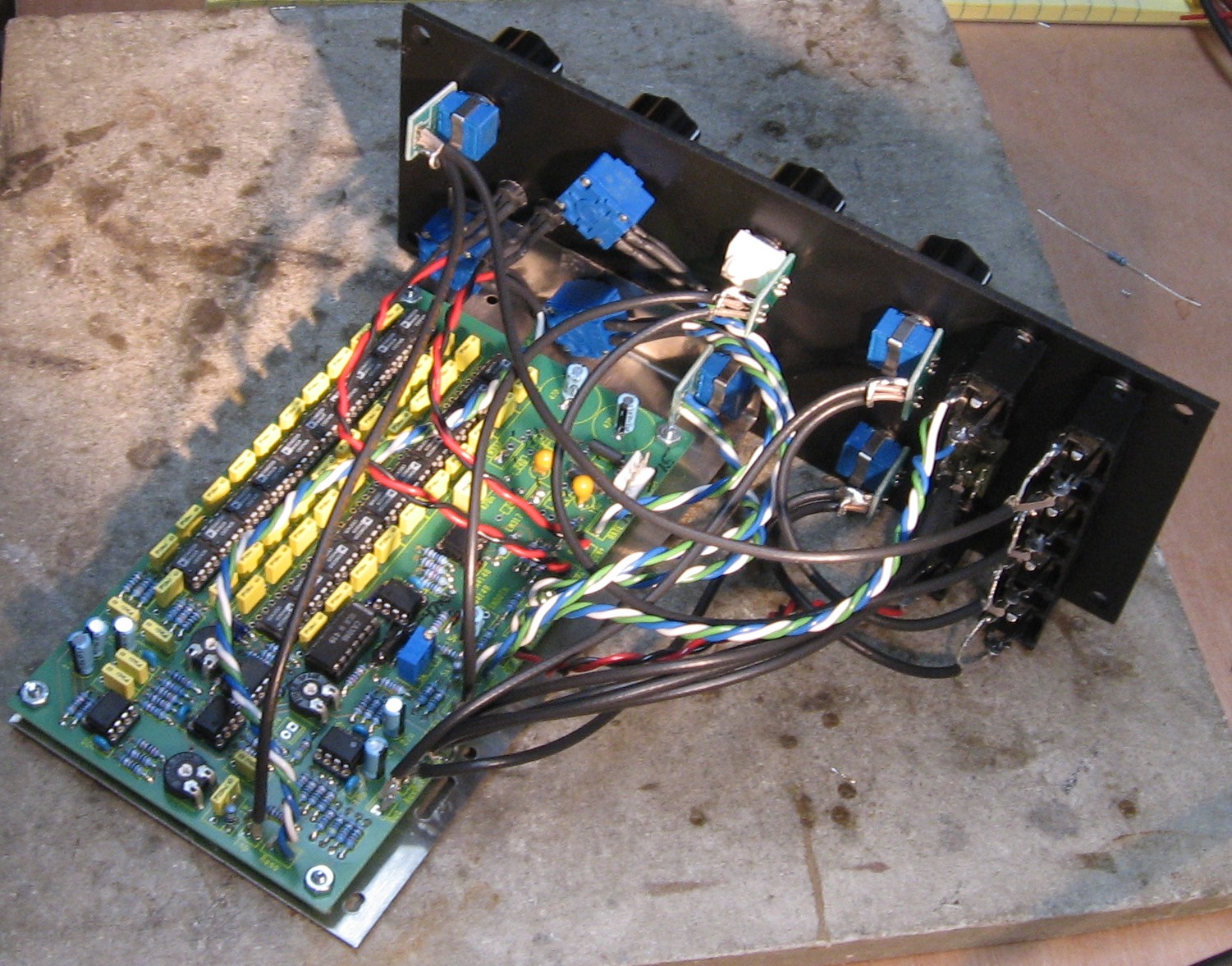
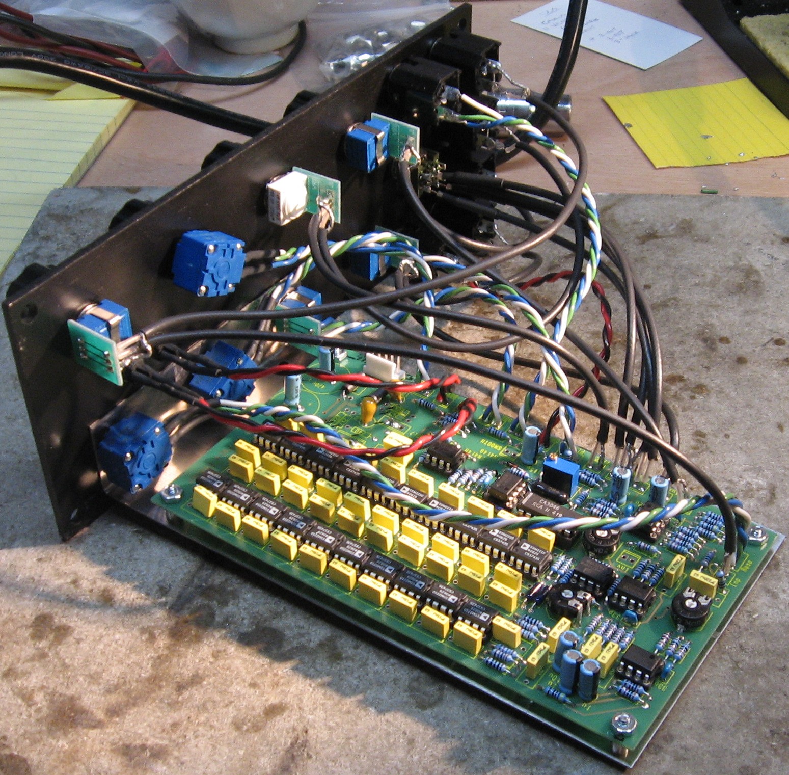
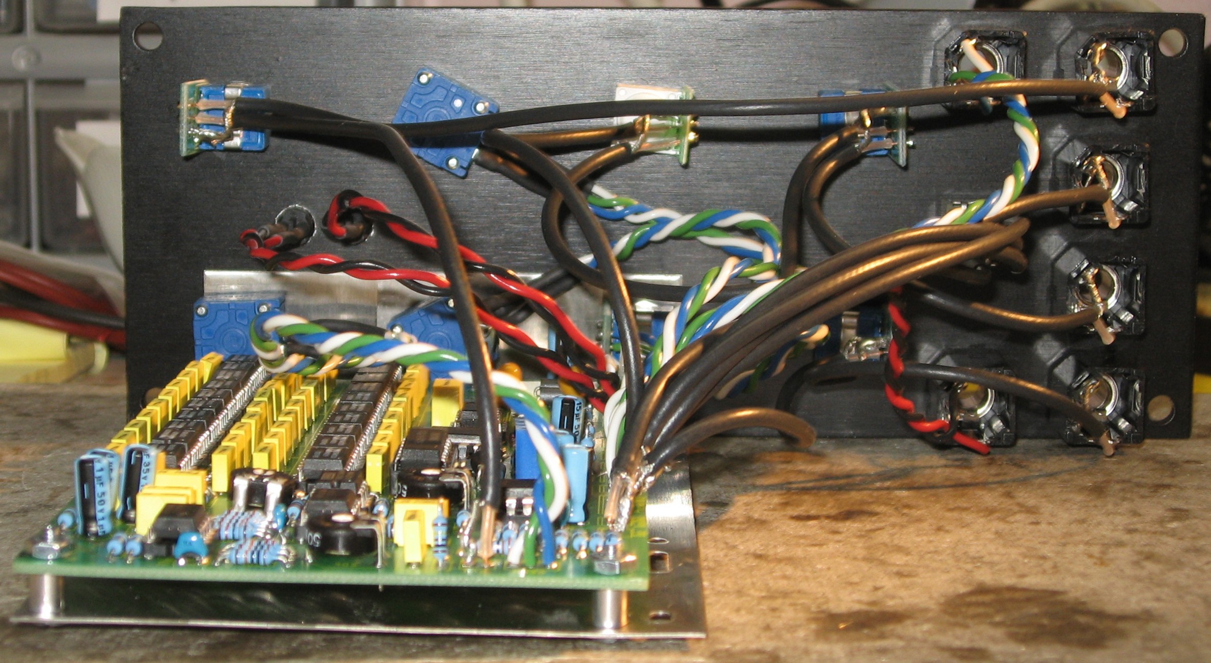
In all of Paul's Synthtech modules, the jacks, pots, switches, etc are soldered directly into the board. But Jurgen shows MTA connectors being used for all of these connections. It seems to us that the advantage of using the connectors would be making easy to remove and therefore repair the phaser. The disadvantages are - extra work and creating another place for connections to be flawed. We were thinking we'd definitely want to use the connectors for the rack-version - we can't really predict the length of the wires needed yet - and it's also conceivable that this one might more easily sustain damage and therefore more likely need repair. And then we got email from Gino Wong saying: "I built up a pile of Oakeys with the headers and finally realized that they are a weak point for modulars. You can take a look and see an obvious problem with them. My new rule of thumb is modulars - point to point wires just like Walter Sear not everything needs everything. Headers also come apart at the most inopportune times. "Standalones on the other hand should be easy to take down and take apart. I think that stand alone gear has weak point because of handling by strangers. Headers, wire bundles secured with ties, extra bypassing, protection resistors and fusing are all good ideas for road gear especially guitar racks. Jacks , pots on headers and even an extra board that can be dropped in in a sort of reverse situation is possible. Very important, label thoroughly even to the point of stupid, I have had to drop in many a Yamaha output board and channel strip. "Hard wiring a modular makes sense you can see where you are going for fixes and modifications and that is important. Modulars and standalones are two different beasts even if you gig with them both." Well, that settles it for the guitar rack version. We'll use the MTA connectors throughout. And the MOTM version - we'll hard-wire.
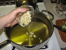
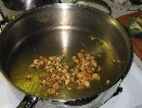
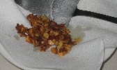
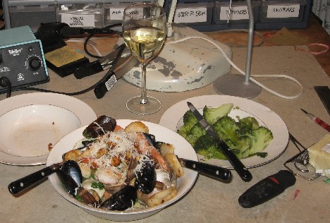
Now to attend the growling stomach |
||
|
|
||
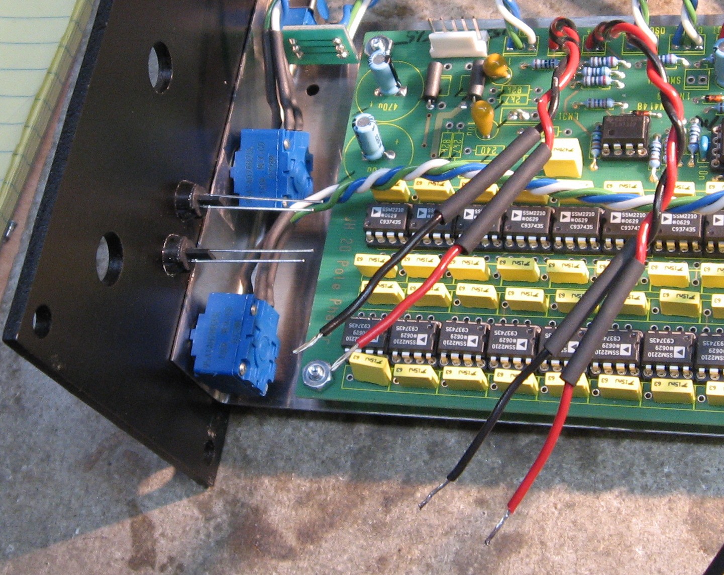
Construction Phase 2(April, 2009) All the stuff in Phase 2 gets soldered using "No-Clean" Solder and the PCB doesn't get washed off from here on. |
||
|
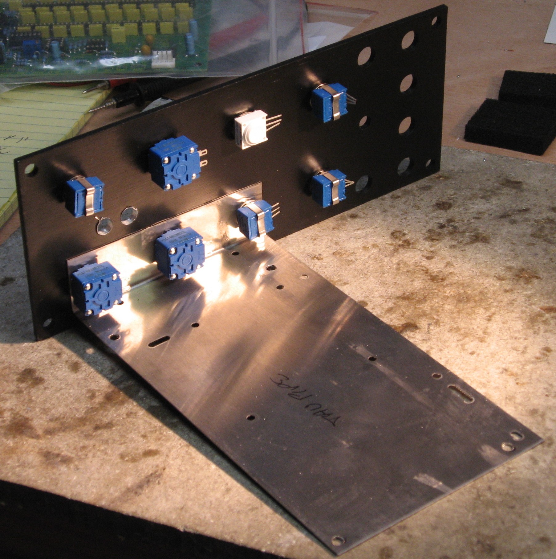
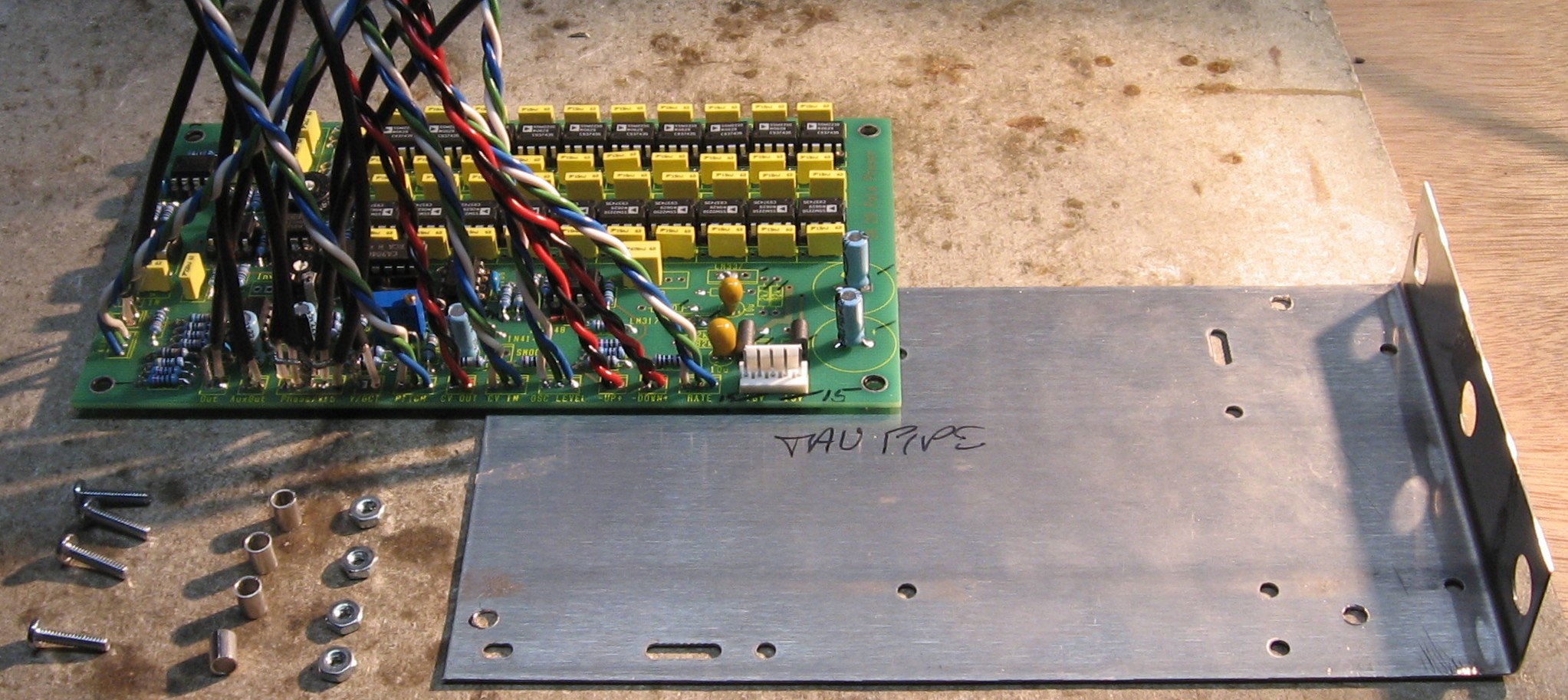
Prepare Mounting Bracket OK - now we considered how to mount the MOTM version to the Front Panel. The "3 Pot Stooge Panel" looks like it'll work fine.
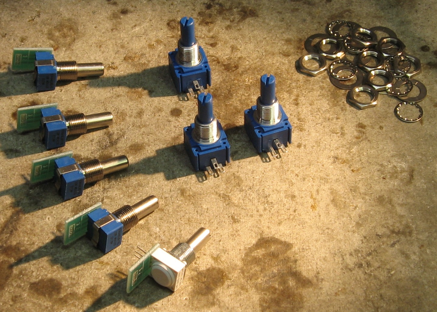
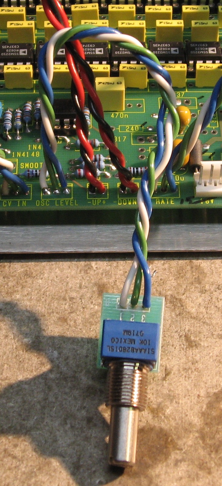
Consider Potentiometers We'll need four 10K log pots, three 100K lin pots, and one 1K log pot.
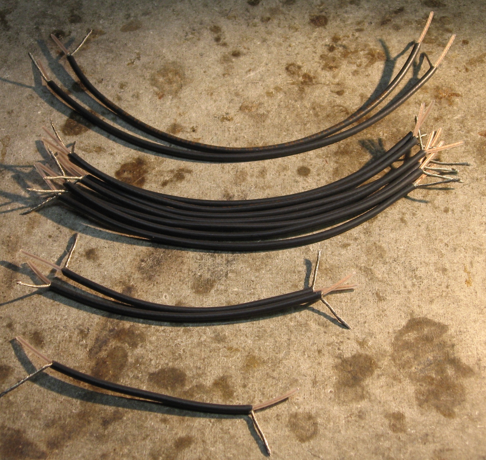
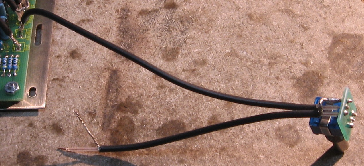
Prepare Connection Wiring Working around the left and bottom of the PCB, we did some measuring. Here's what we'll need:
10" coax - INPUT jack to INPUT pot Or: Coax -
(2) 10-inch Wire -
(1) 9" twisted triple
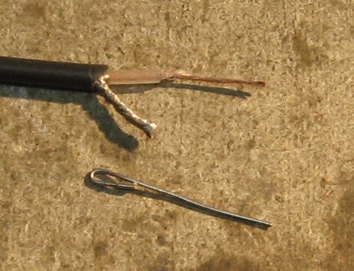
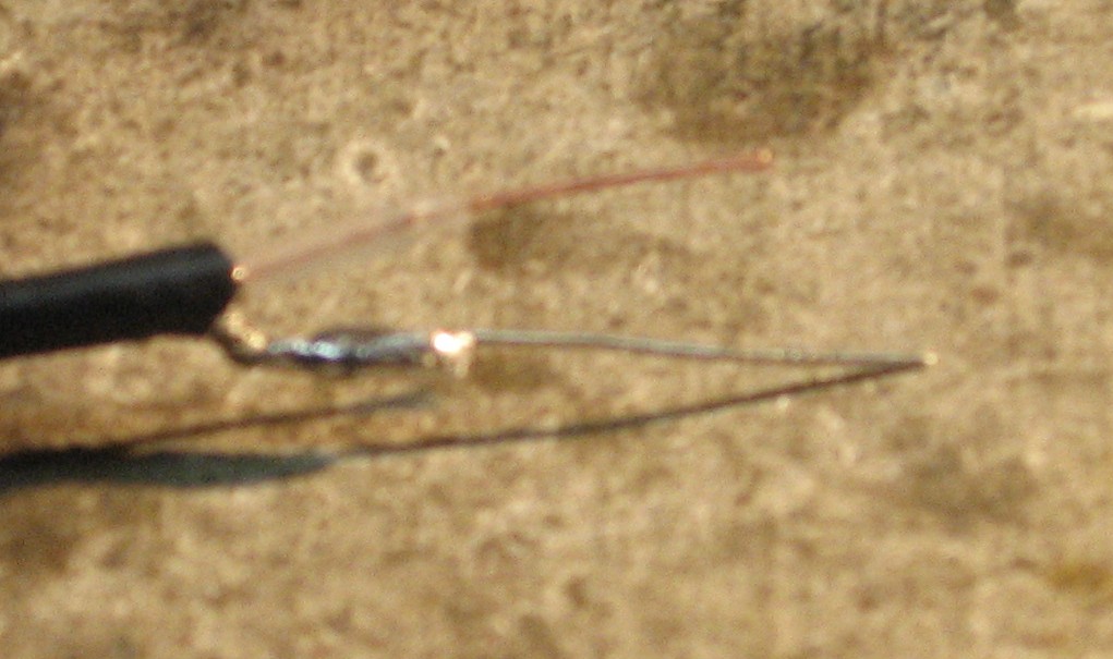
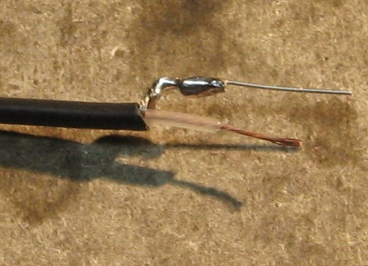
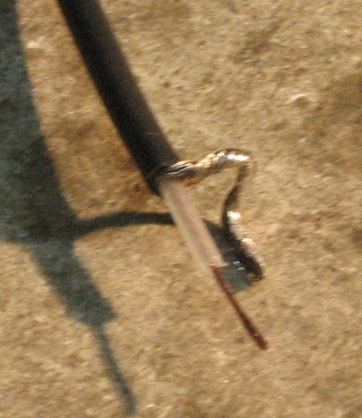
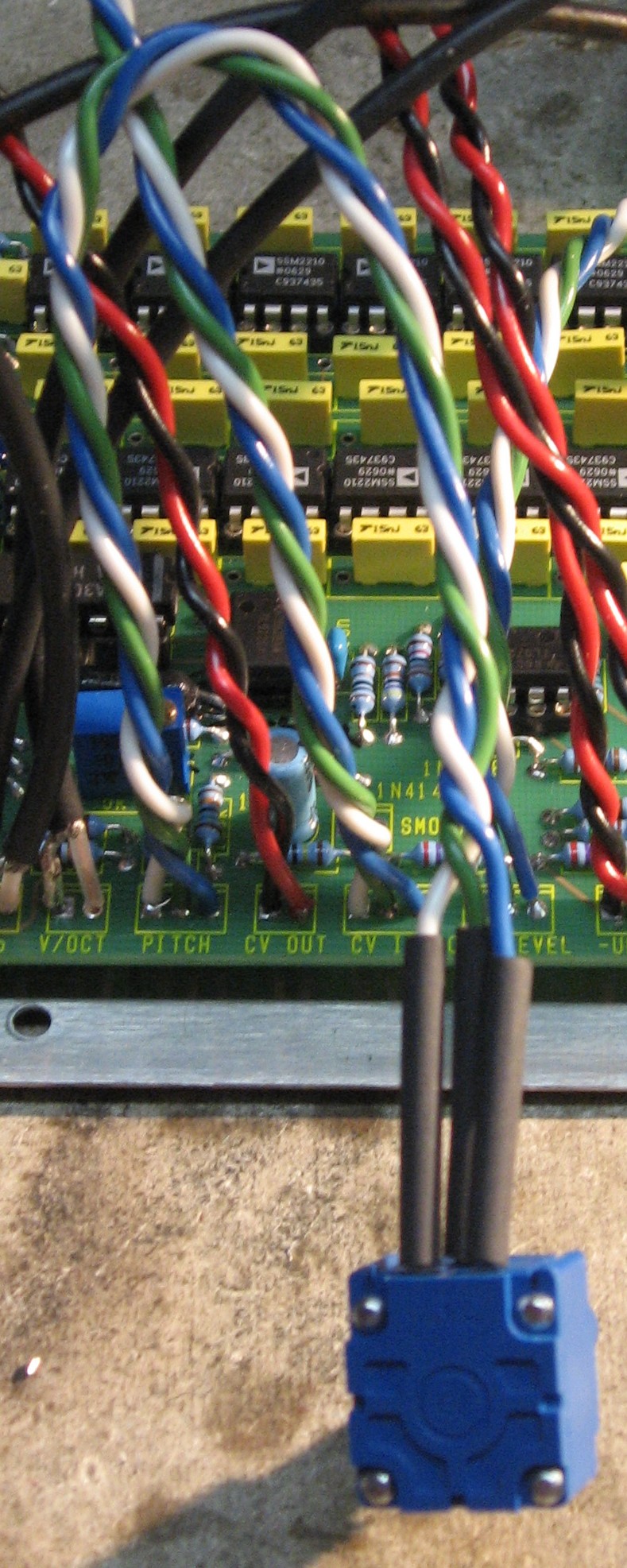
The shield of the coax is too big to go into the holes in the PCB, so we soldered a bit of resistor lead onto the coax.
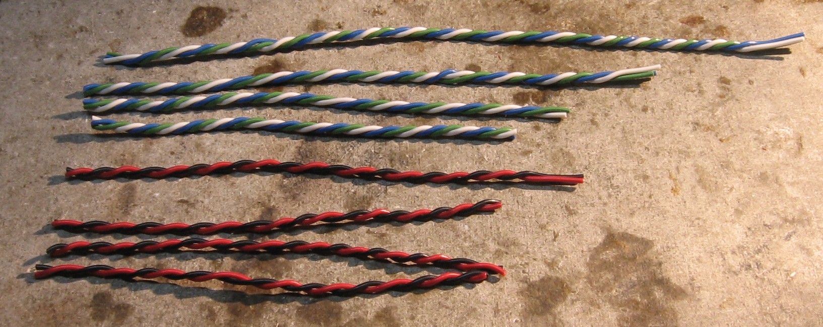
We've figured out that the best way of making lengths of twisted wire - pairs and triplets - is to cut long pieces of the wire first, then cut to the lengths needed.
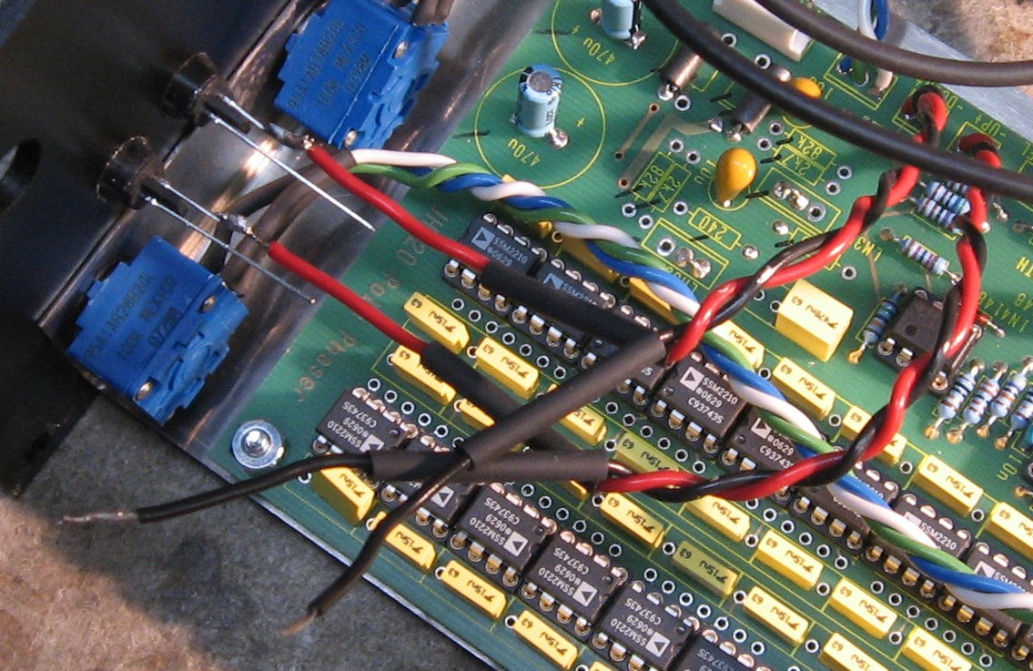
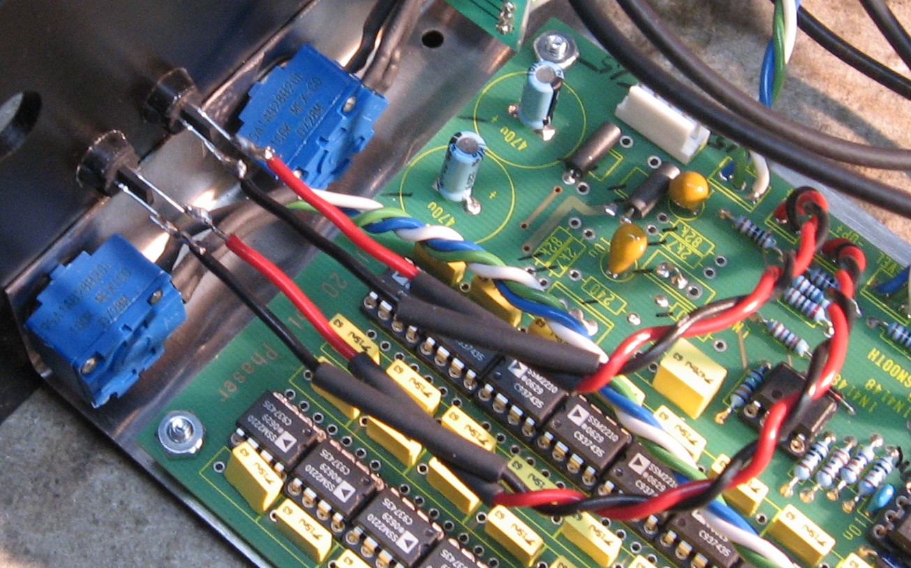
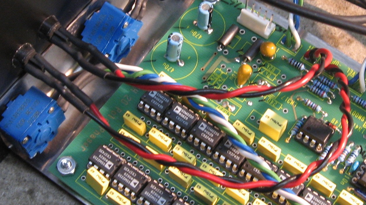
Coax into the PCB
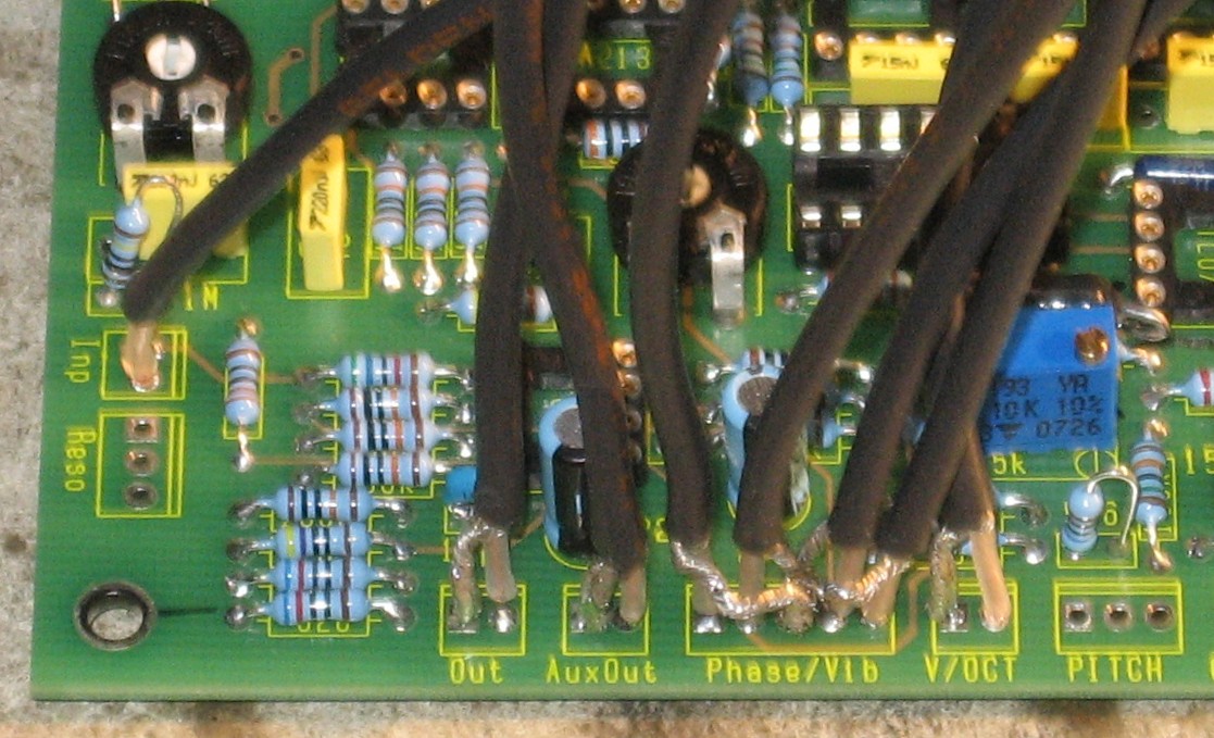
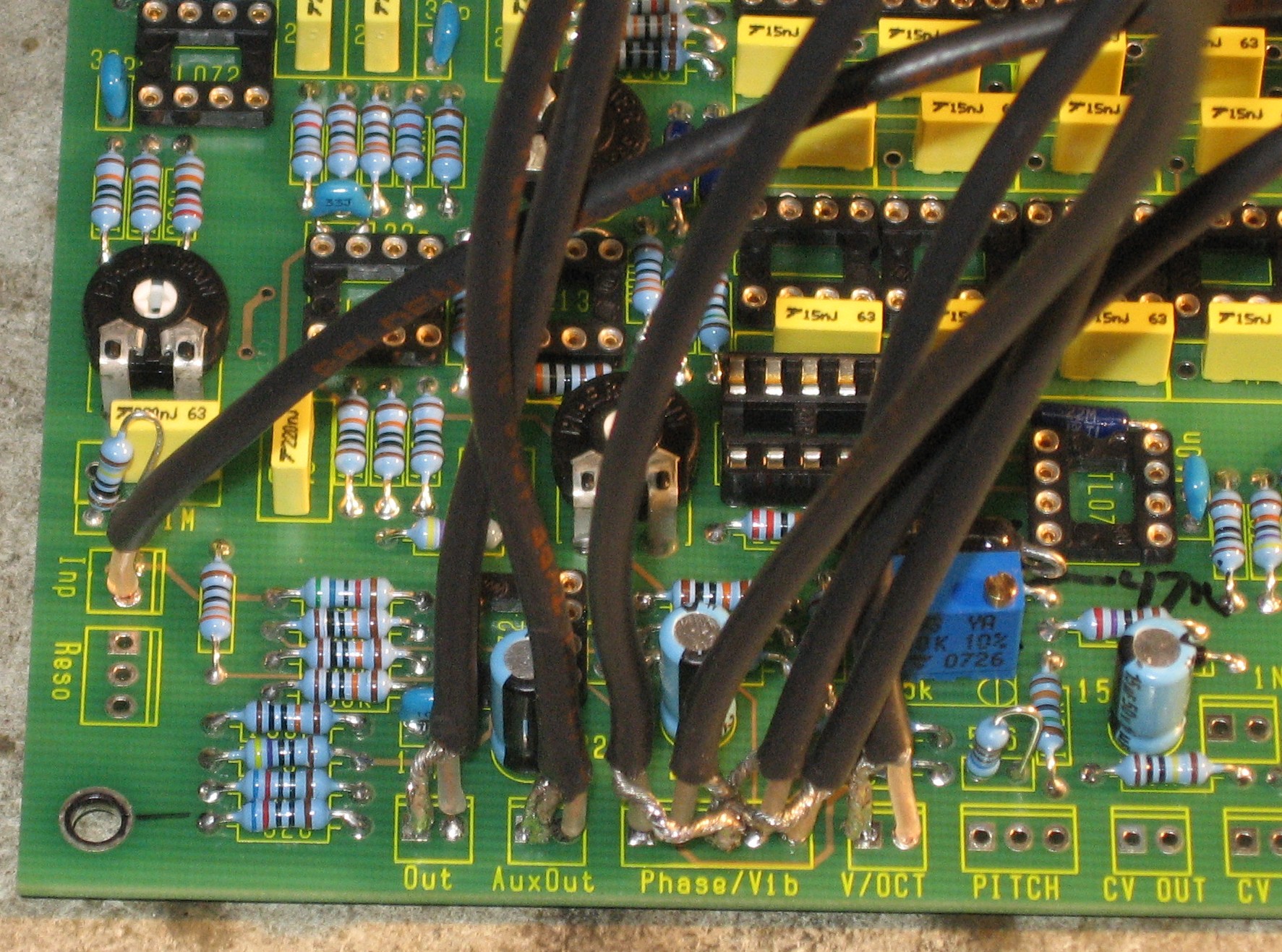
Wires into the PCB
ICs into the sockets
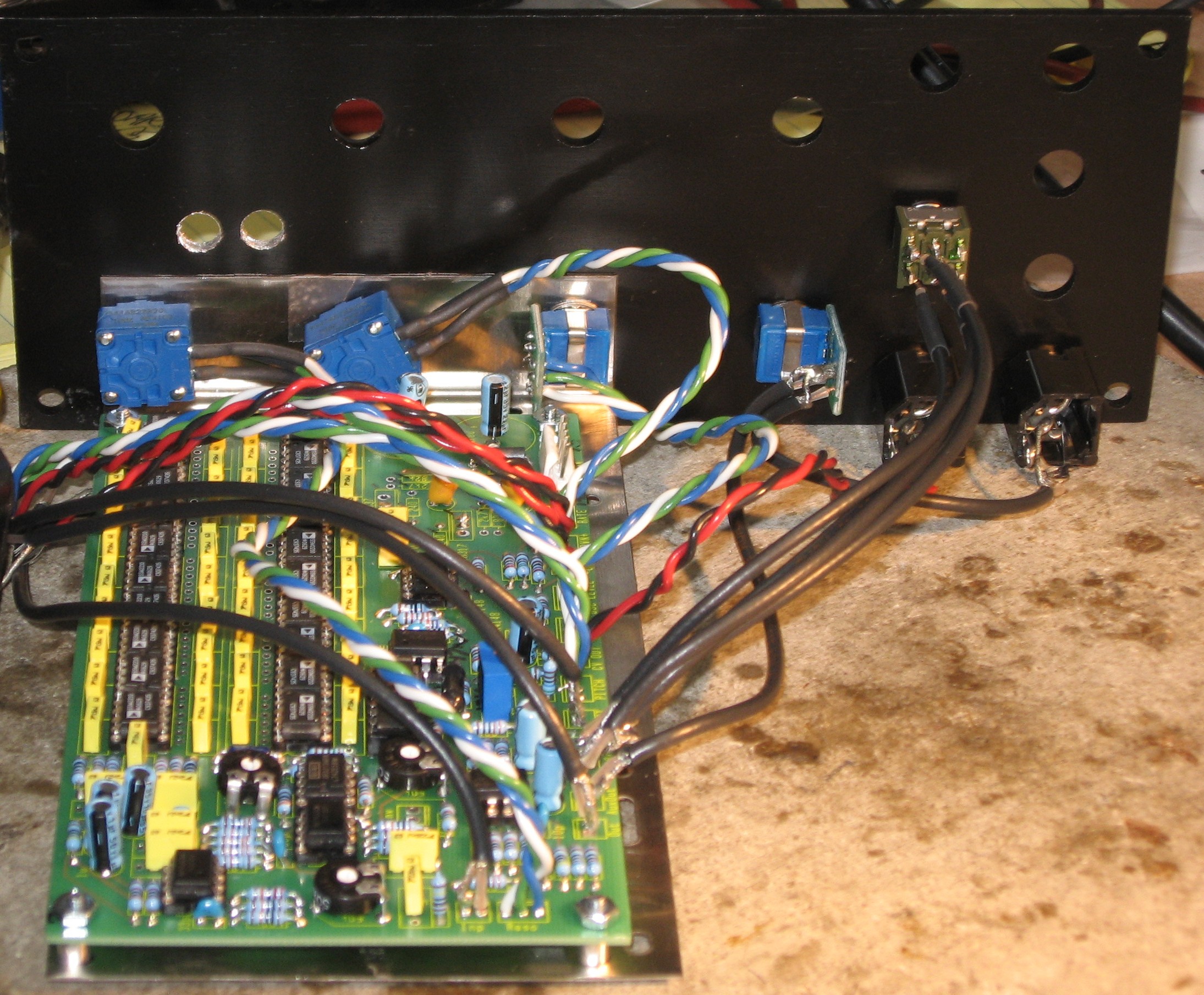
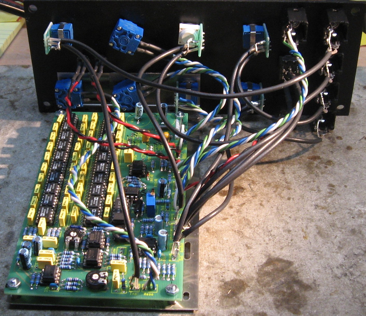
Mounting Bracket Now for mounting the PCB onto the 3 pot "Stooge" mounting bracket. We had to drill holes in the bracket to match the PCB.
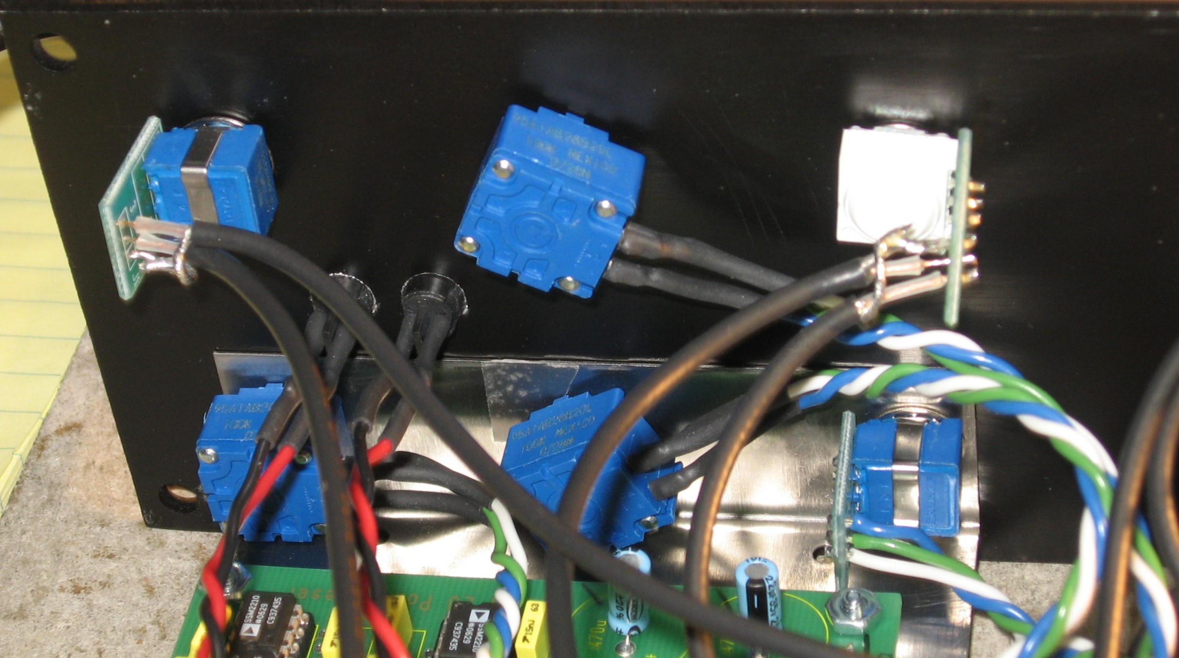
Panel Connections First, we're going to focus on the three pots that will attach the Stooge bracket to the panel.
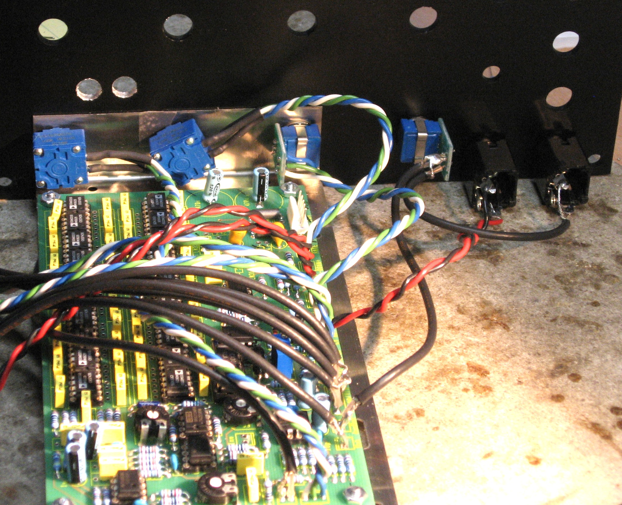
So now, we're going to attach the Stooge Bracket to the Front Panel
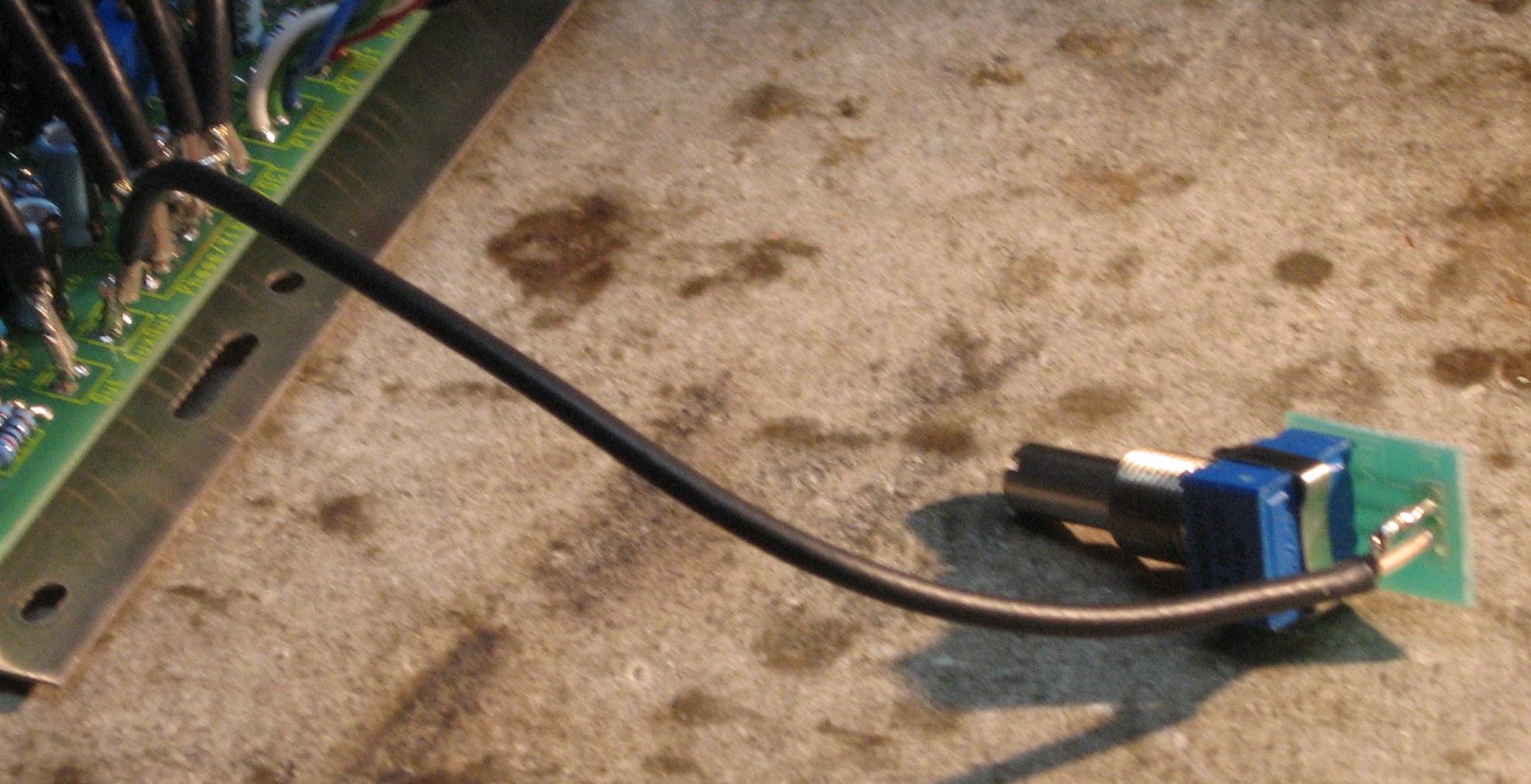
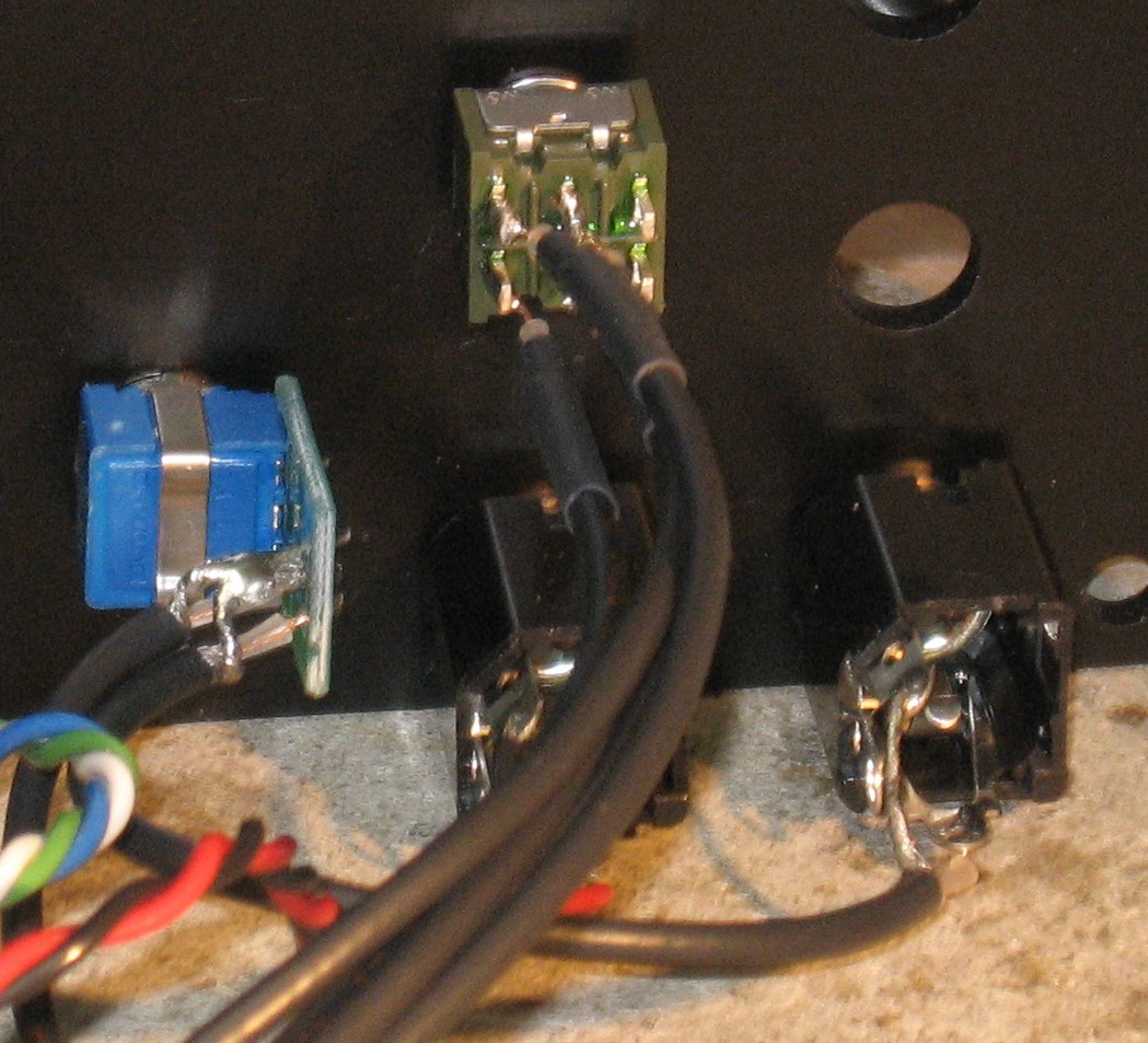
Aux Out The Aux Out is accomplished with coax - from the board to the Pot, then to the jack. But the holes in the PCB and in the pot's chicklet are too small for the coax shield. So first, we soldered a bit of scrap resistor lead to the coax shield at each end.
So then coax gets soldered into the chicklet that will go to the Jack. To accomplish this, the coax shield has to reach around the first connection.
The rest of the "Right Column" The AUX OUT pot, the CV IN jack, and the AUX OUT jack all mount into the panel.
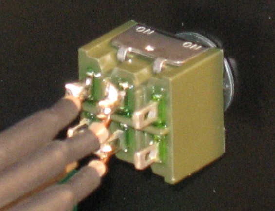
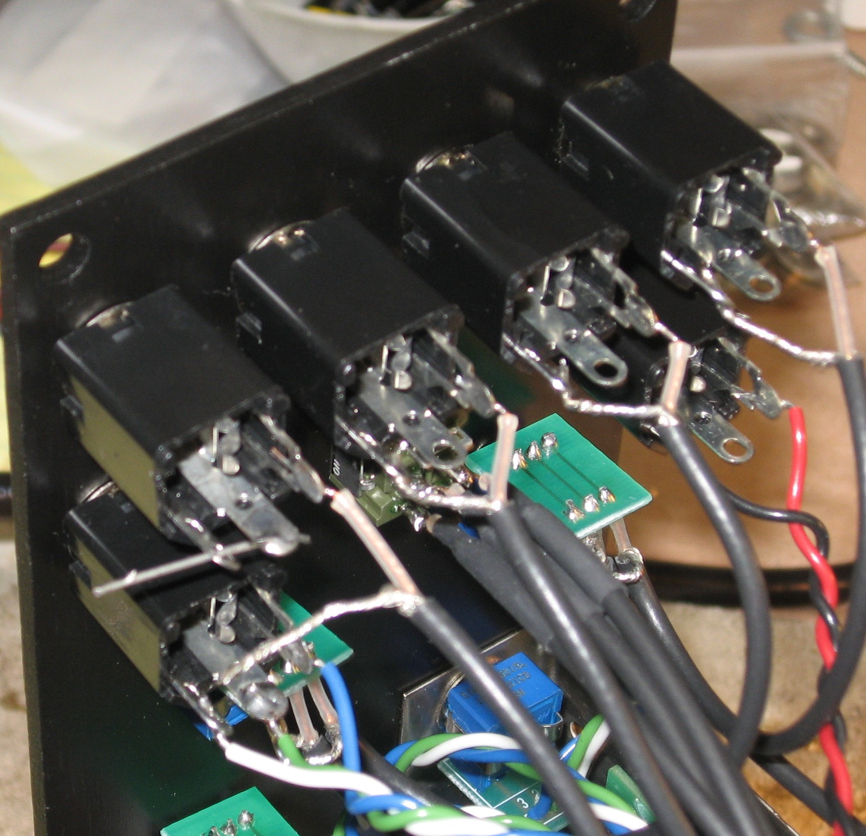
The MODE switch The MODE switch requires those four pieces of coax already soldered into the PCB.
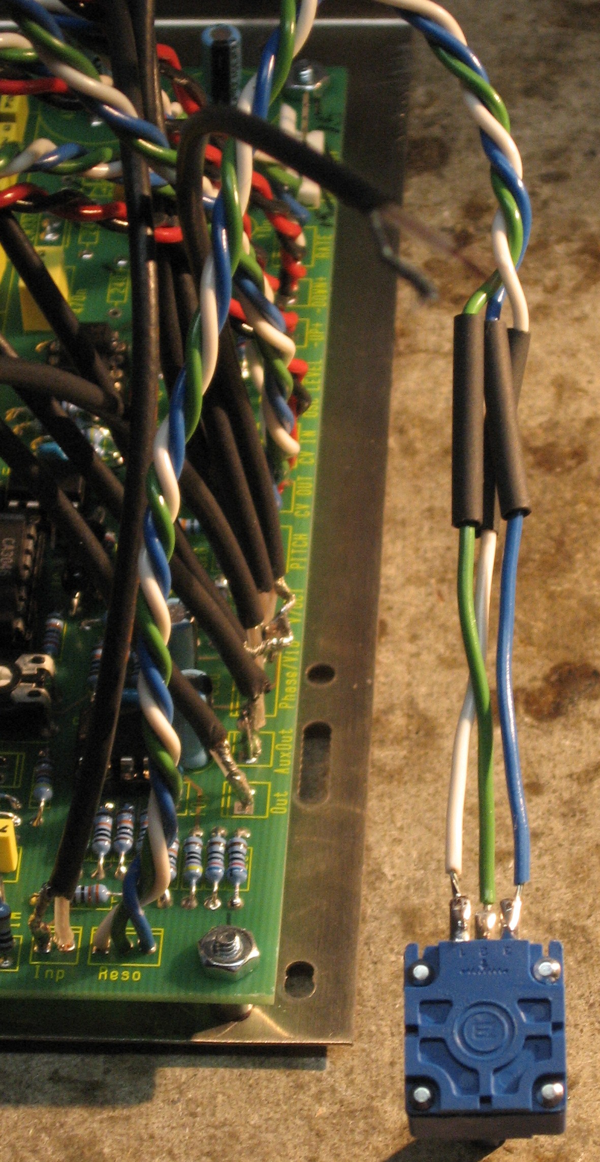
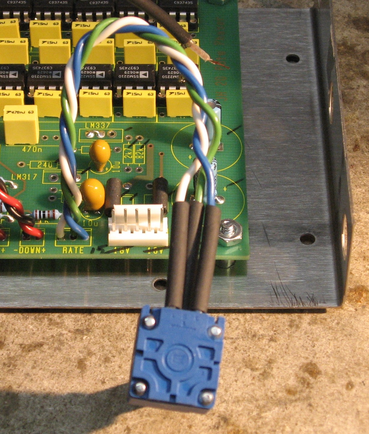
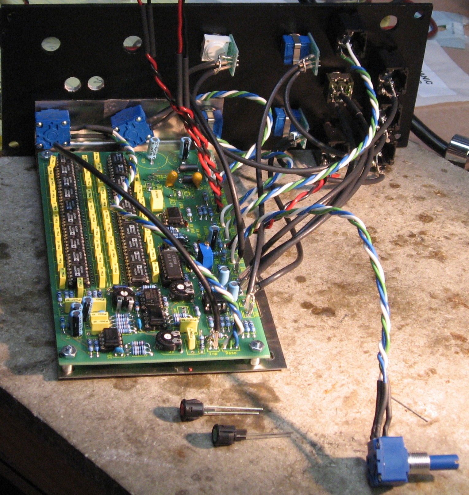
The "Left Column" So then we started on the Left Column - the 1K log V/OCT pot, the 10K log MAIN OUT pot (wired up just like the AUX OUT pot), and the CV IN jack.
Connecting up the LEDs
The PITCH control
V/OCT jack / Input control
|
||
|
Construction Done |
||
|
|
||
Set up / Testing |
||
Use Notes |
||
|
|
||
Panel Design EvolutionThis is how we developed the panel design |
||
|
Here's our first attempt at design—a 3U wide panel. We didn't really fully consider function, we just put everything on a panel like this:
|
||
|
After review by Mike, here is his revision and comments:
|
||
|
After several reviews and improvements, Mike, Scott, Jürgen, Will and I came up with the final design. Jürgen told Mike that summing didn't really make sense.
|
||
|
And finally, we thought that we could use a dual color LED. But we were wrong. Still we wanted to be true to Jugren's design, so we drilled an extra LED hole for the green LED like this:
|
||
|
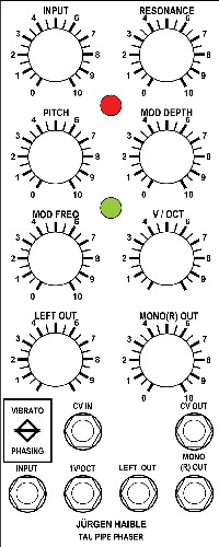
Will and I then developed the following rack-mount panel design for my stage equipment guitar-rack. Thanks again to Mike for his suggestions.
|
||
|
|
||

)
)
)
)


 "I've been re-thinking the Tau Pipe.... see my minimal layout attached.
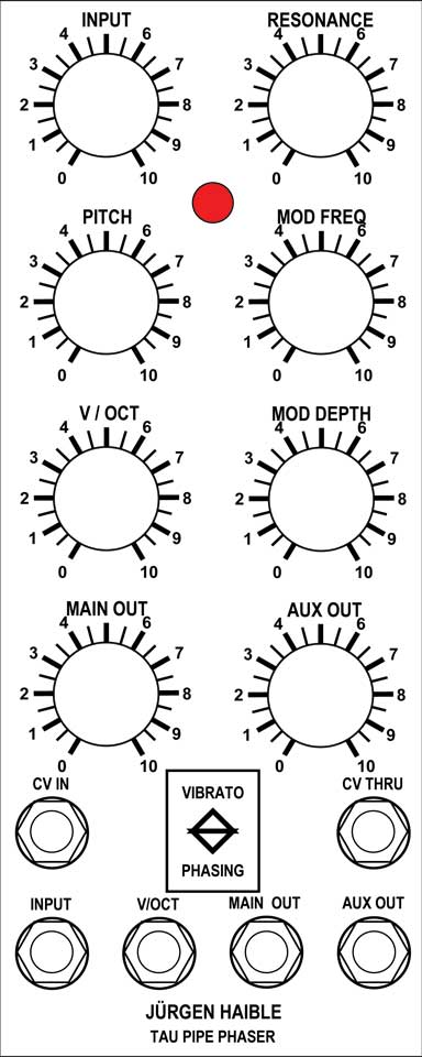

|
The fine Print: Use this site at your own risk. We are self-proclaimed idiots and any use of this site and any materials presented herein should be taken with a grain of Kosher salt. If the info is useful - more's the better. Bill and Will © 2005-2011 all frilling rights reserved
|