Bill and Will's Synth
|
||
Table of Contents |
||
|
This page has become really long, so here's a table of contents that we hope will make it easier to traverse: Background - presents Jurgen's initial description of the effect Recapitulation of Construction/Feature Options - presents a simple list of the different possible implementations Option Details - presents the details of our implementation - you'll need to consider the full set of options as presented by Jurgen in deciding how you'll build yours Parts - presents a Bill of Materials and notes about it Panel - presents how we came up with our panels' design - ultimately Scott Deyo at Bridechamber fabricated the MOTM format one Construction Phase 1 - Resistors, Capacitors, IC Sockets, Semiconductors, Power Plugs, MTA headers Construction Phase 2 - Trimmers, Panel connections |
||
Background |
||
|
Jürgen's site describes the effect: "The "Subtle Chorus" is a variable project consisting of 3 different PCBs that can be combined for various functions.
|
||
|
Fundamental Options:
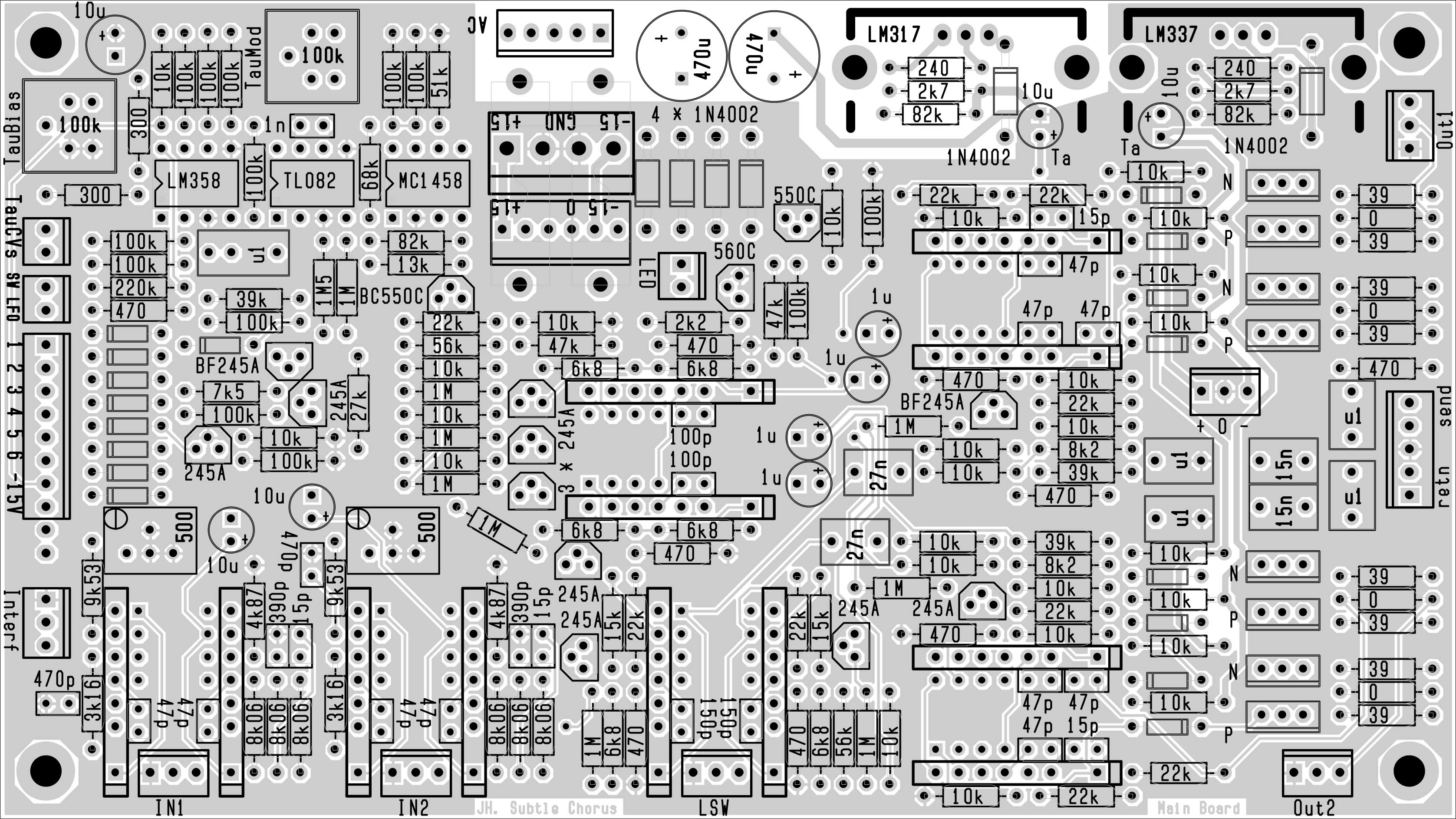
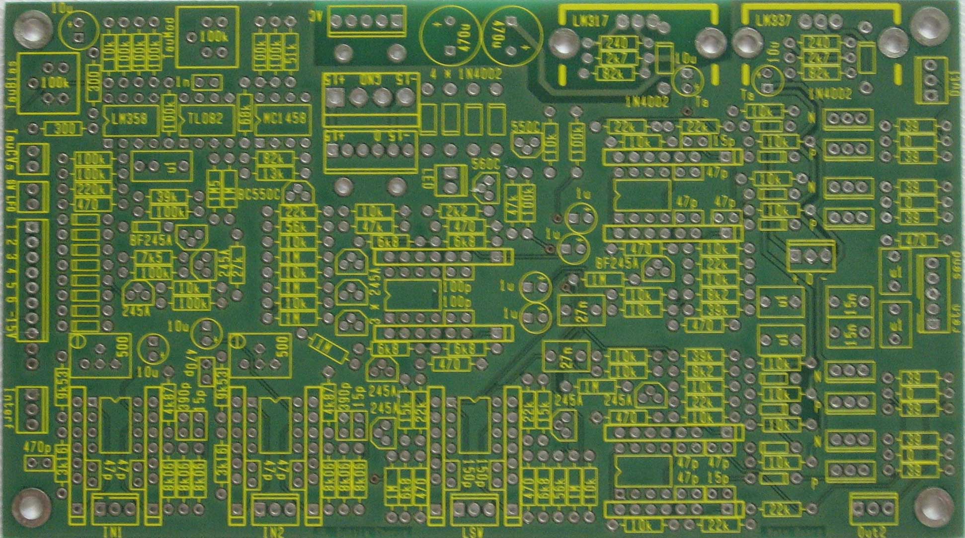
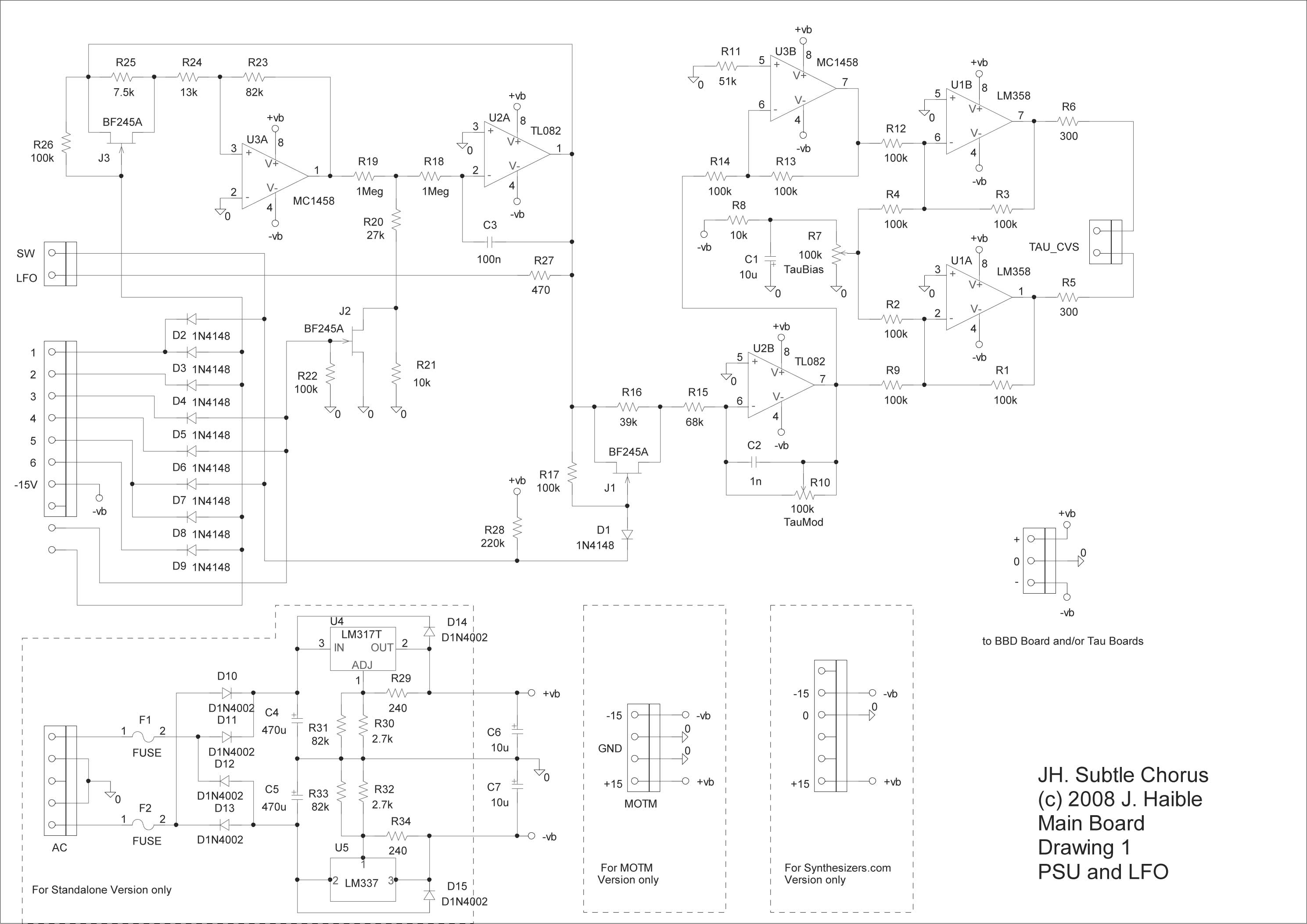
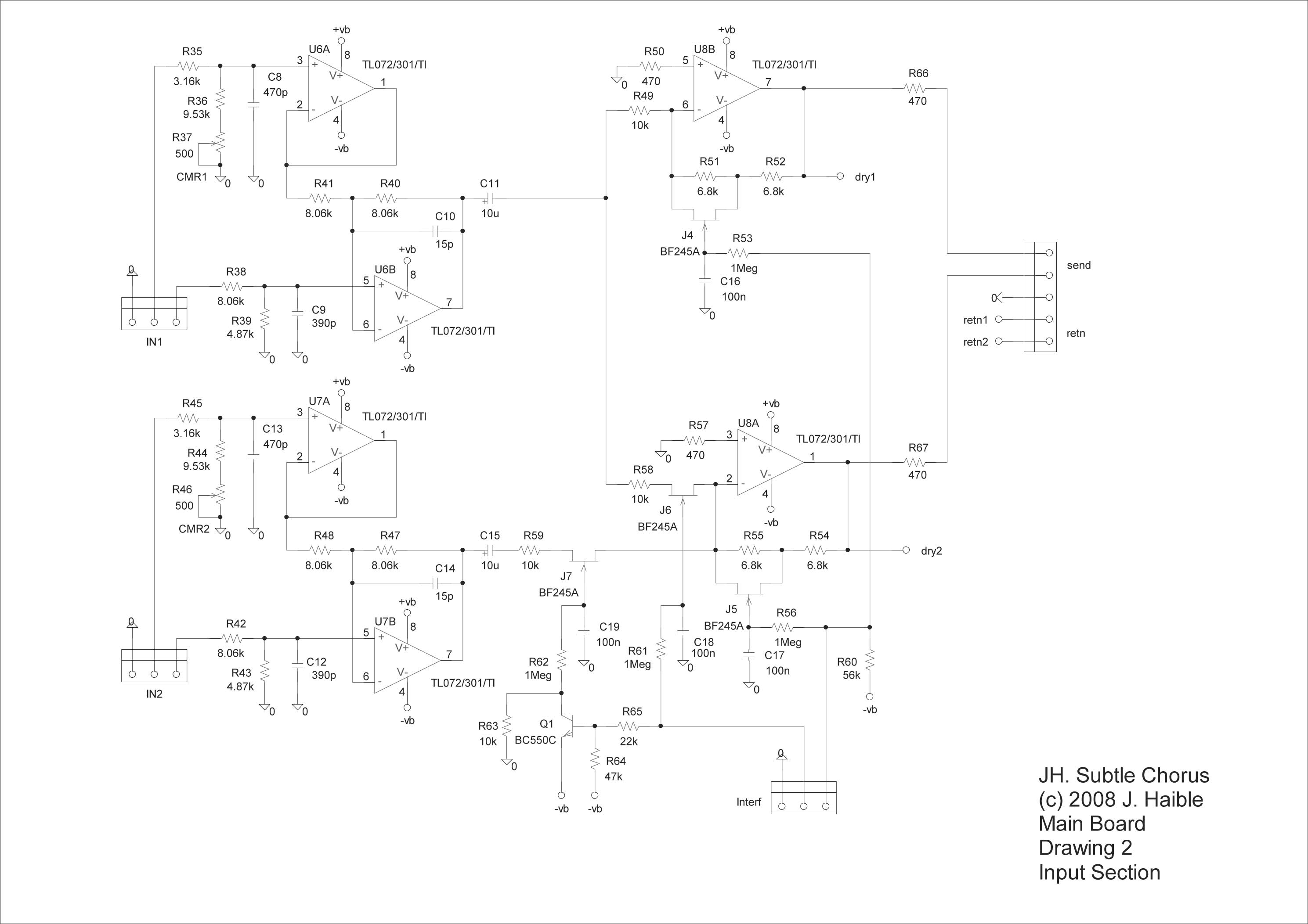
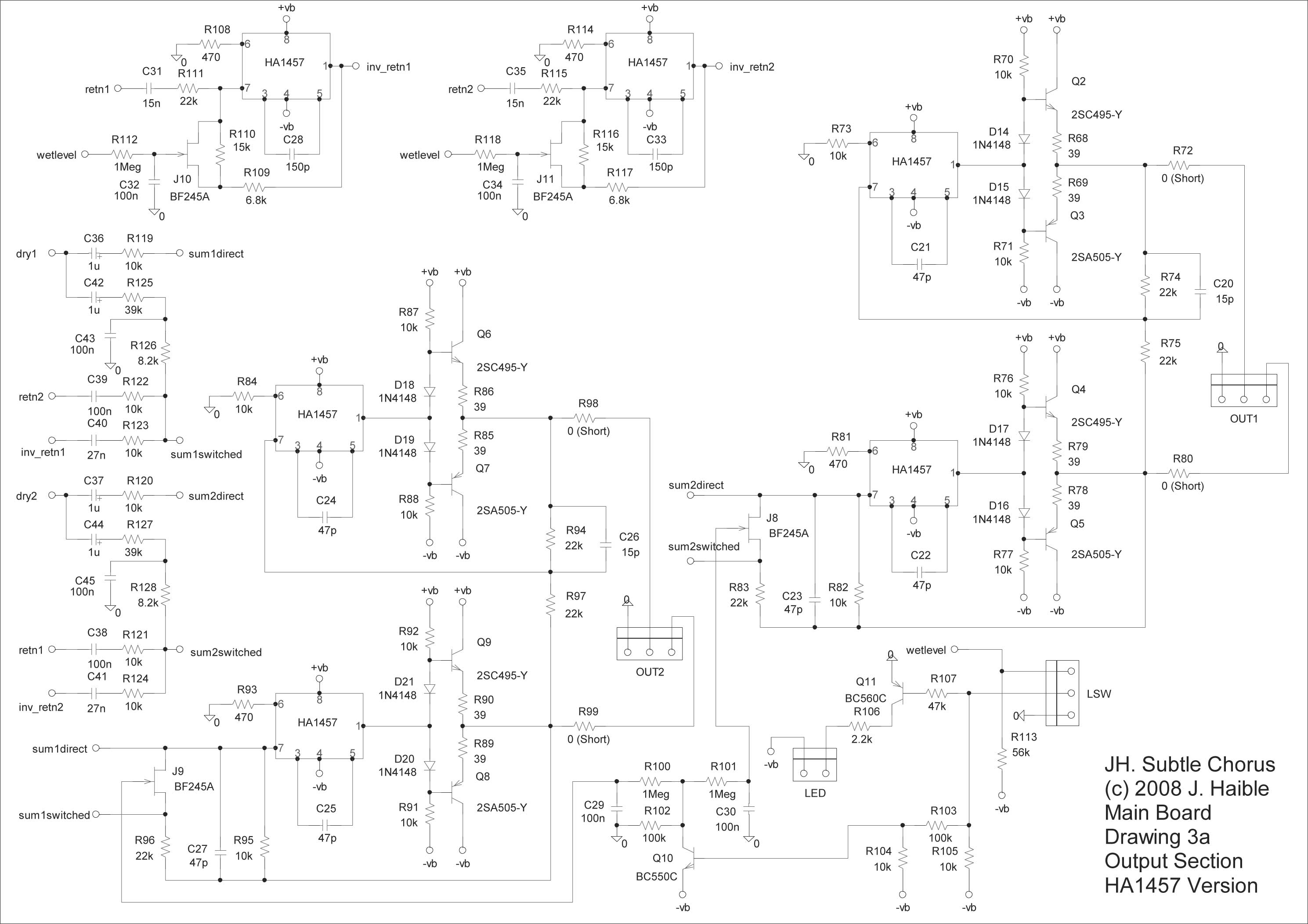
Subtle Chorus Main Board - can be used to control a BBD Board and /or two Tau Boards. The board can be built with the "vintage" HA1475Ws (like we're going to do) or with TL072s & TL071s:
You can see the schematics for the Main Board by clicking these links:
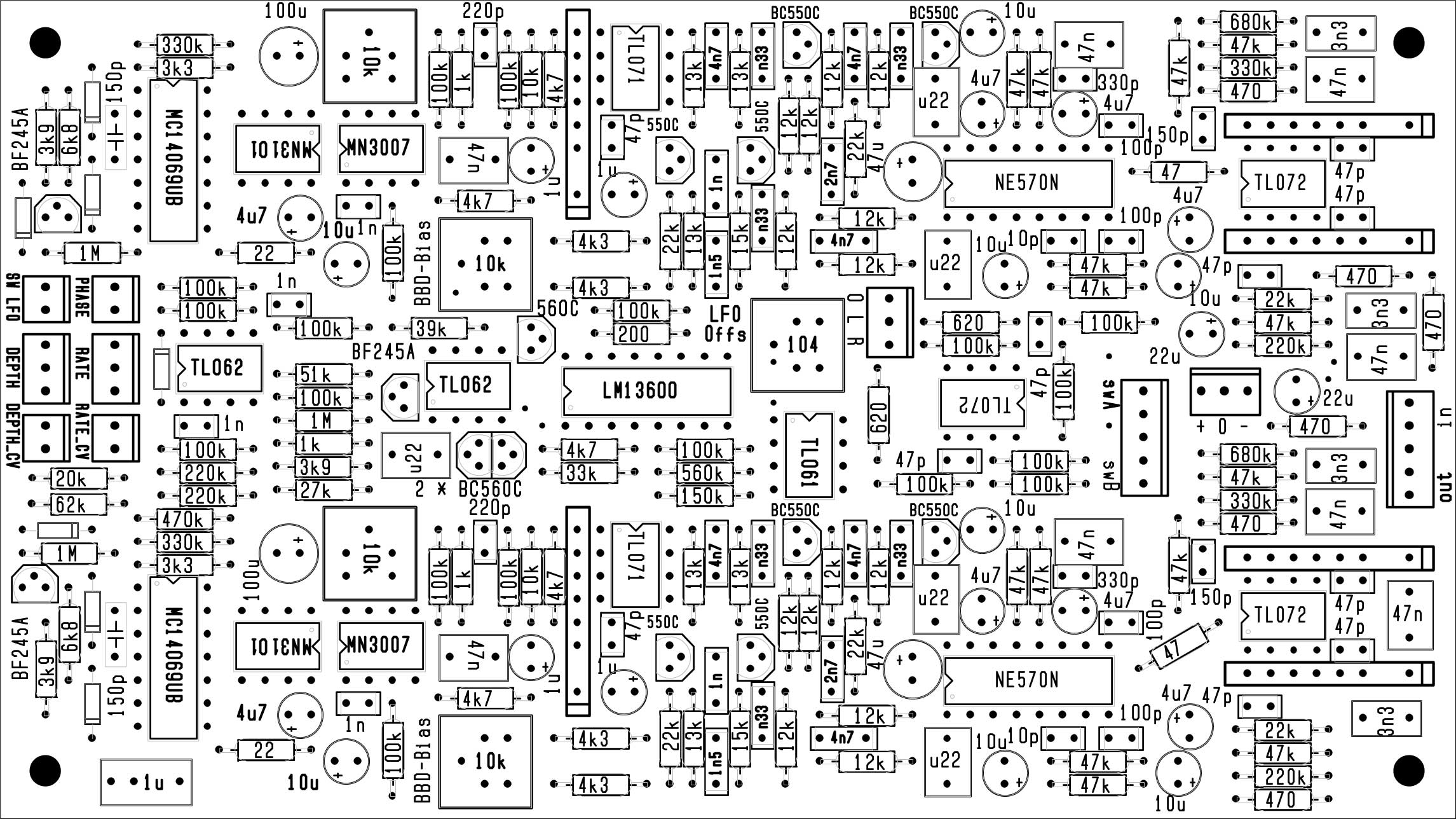
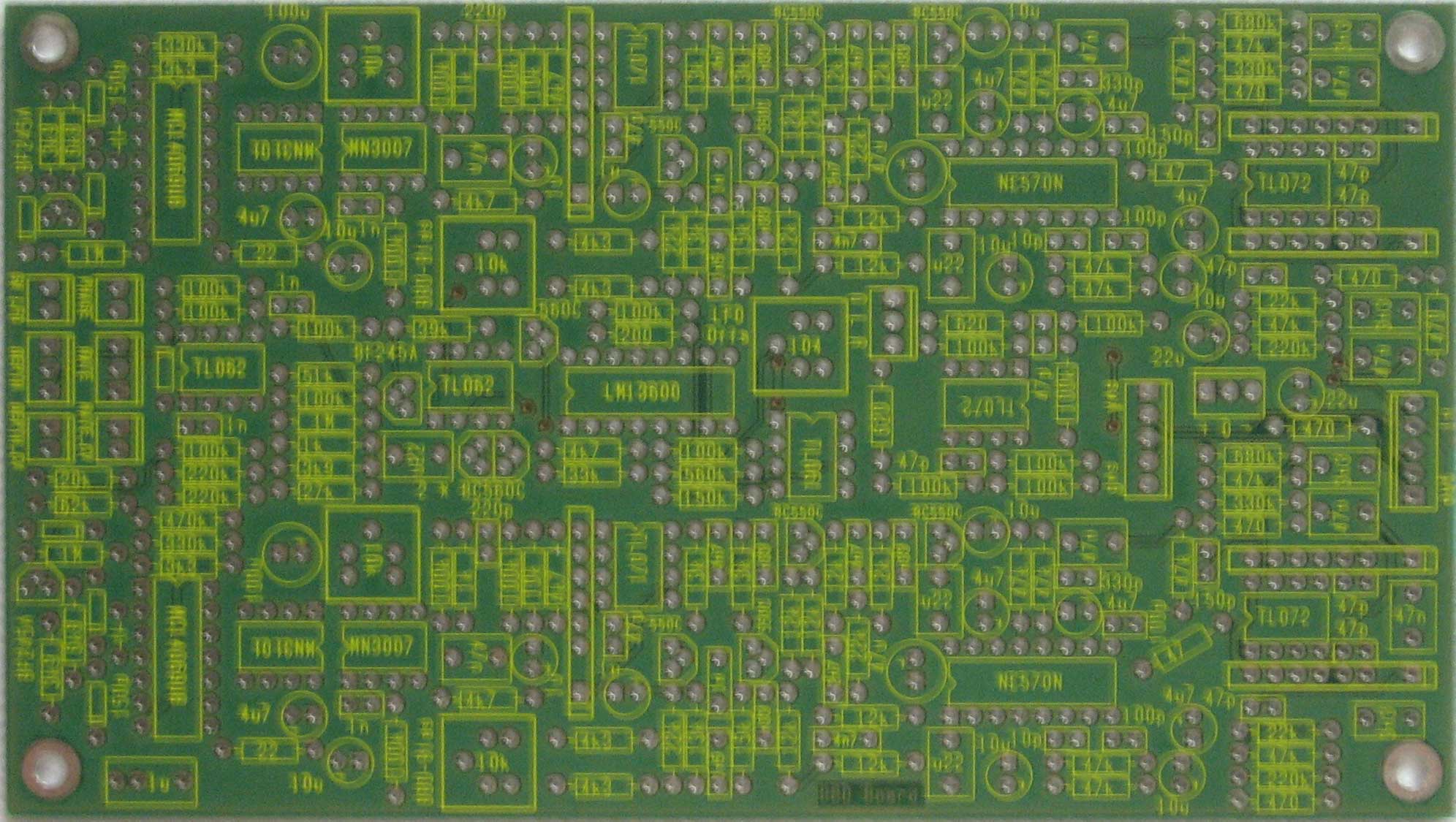
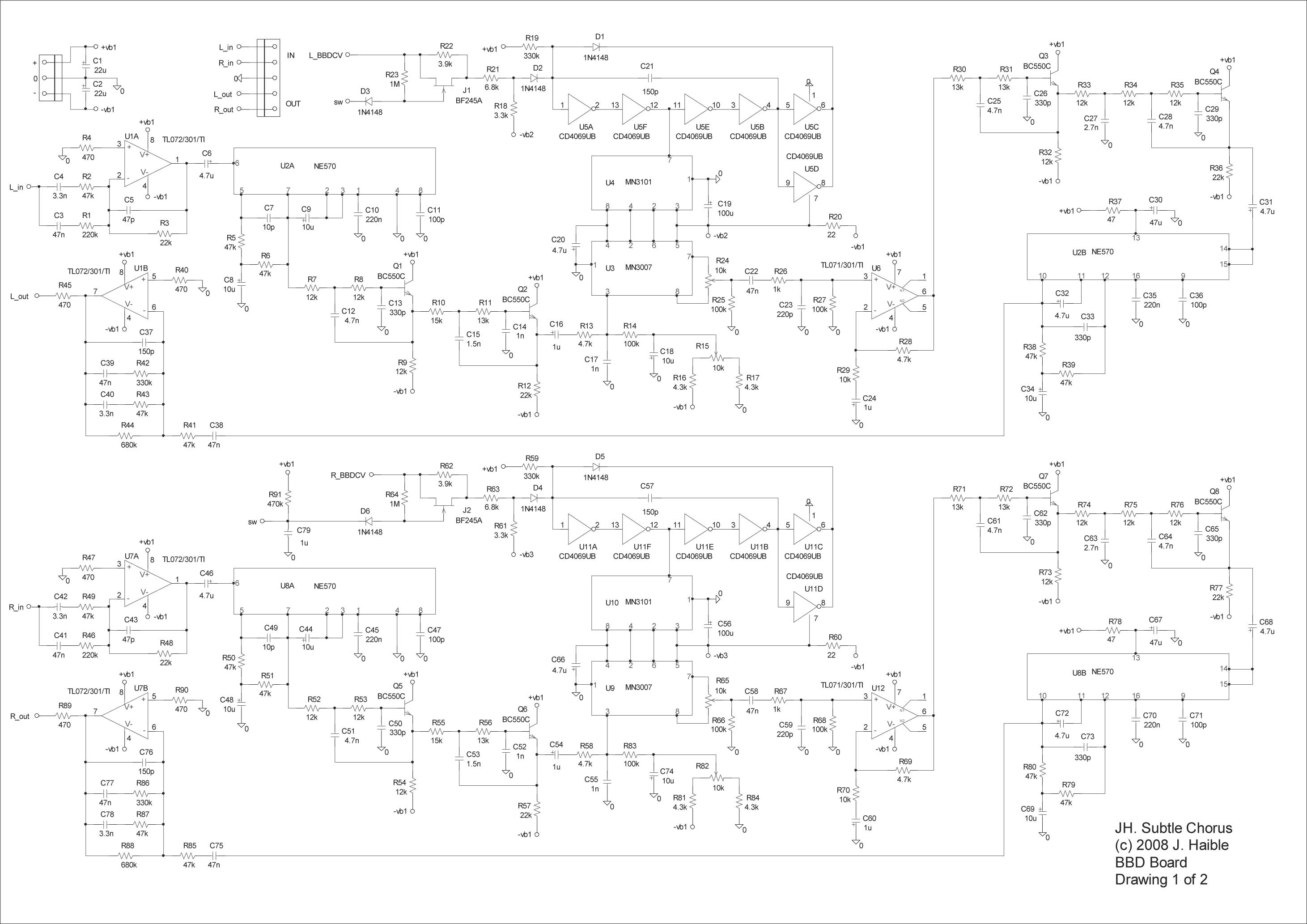
Schematic 1 - LFO and Power Supply Subtle Chorus BBD Board - also can be built with the "vintage" HA1475Ws (like we're going to do) or with TL072s & TL071s:
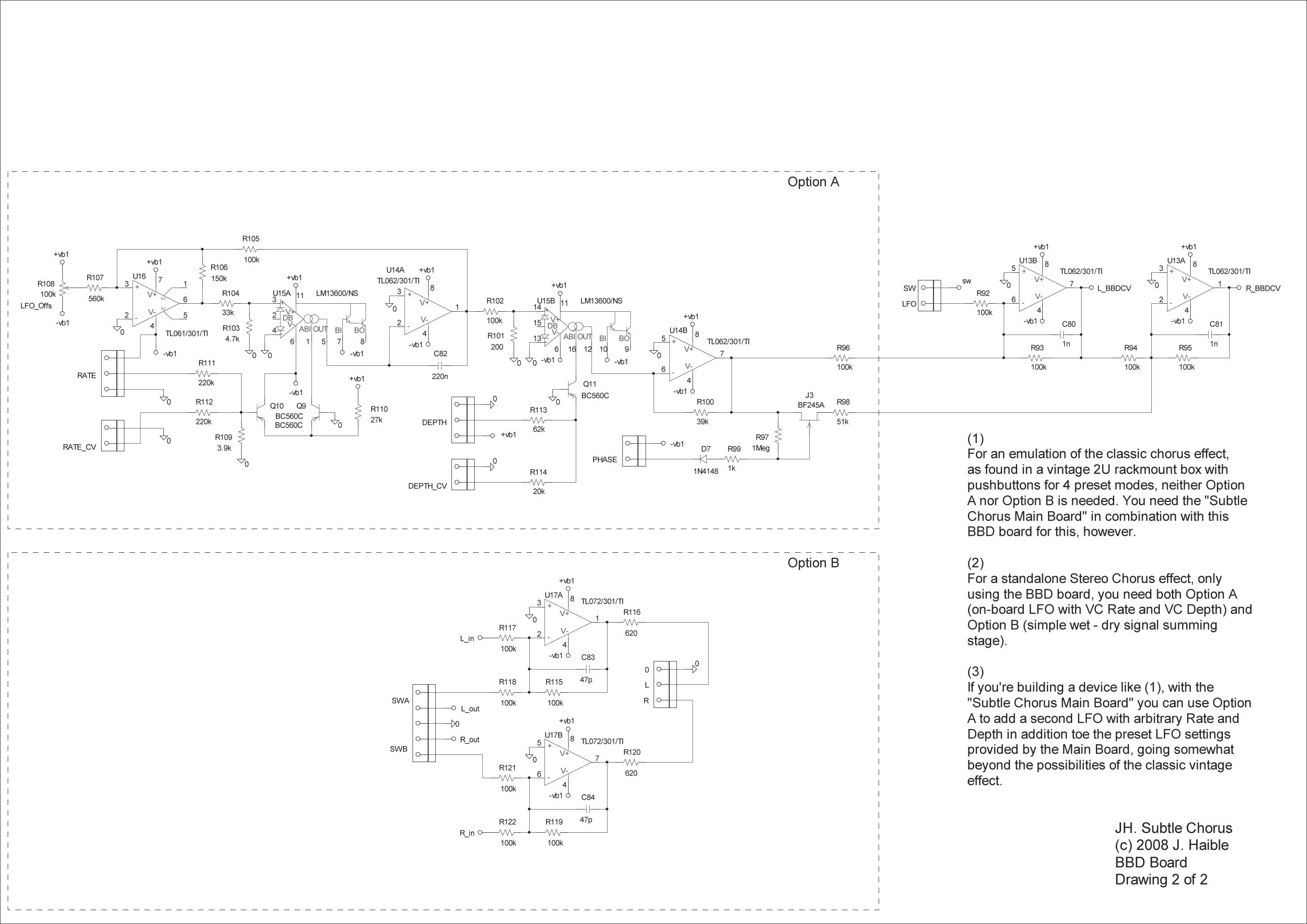
You can see the schematics for the BBD Board by clicking these links:
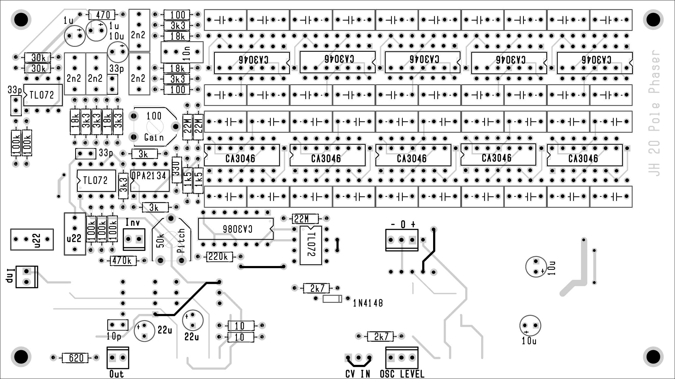
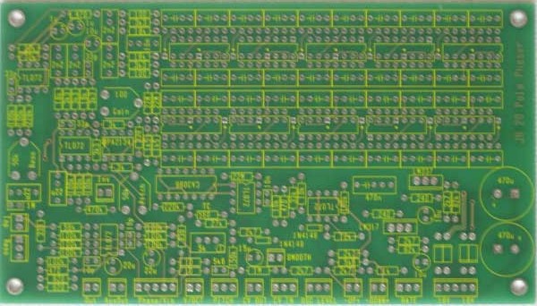
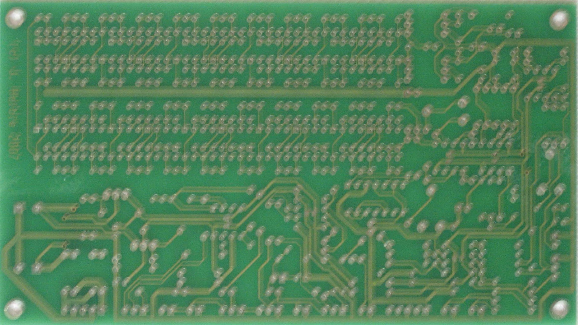
Schematic 1 - BBD Tau Pipe Phase Delay PCBs:
|
||
Option Details |
||
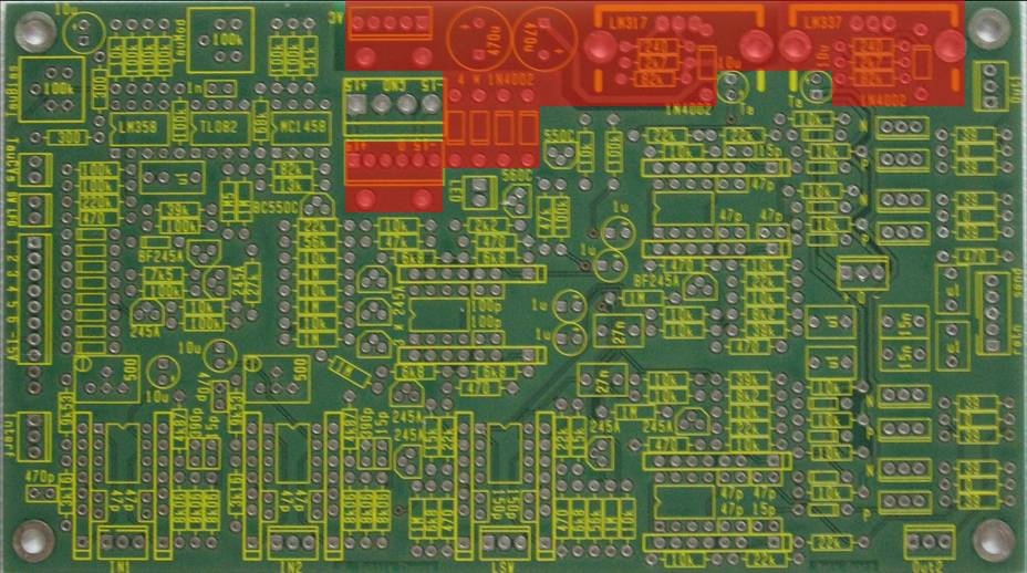
1. Power SupplyThe Main Board serves as the power source for the other boards - if +/-15V MOTM power is used, then the AC power supply components can be left off the PCB. This diagram illustrates the parts that should be left off for the vintage version (in red):
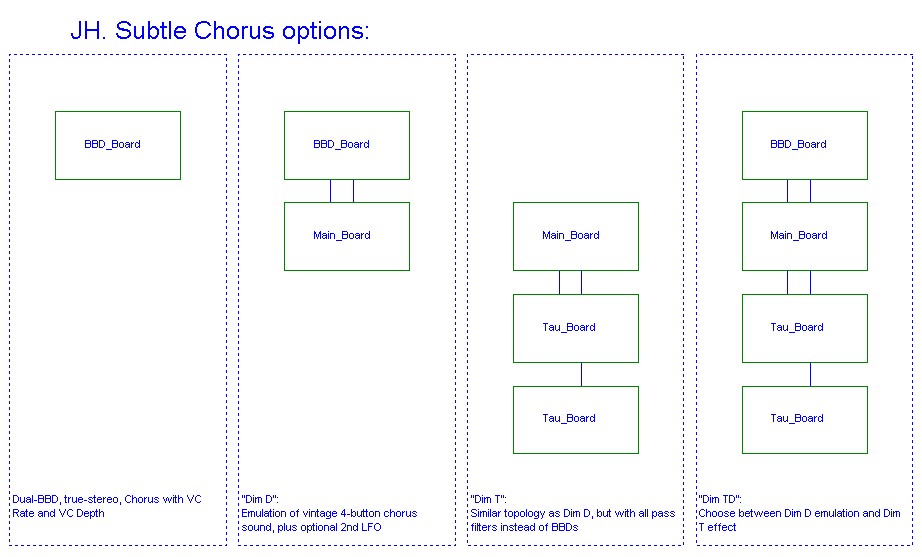
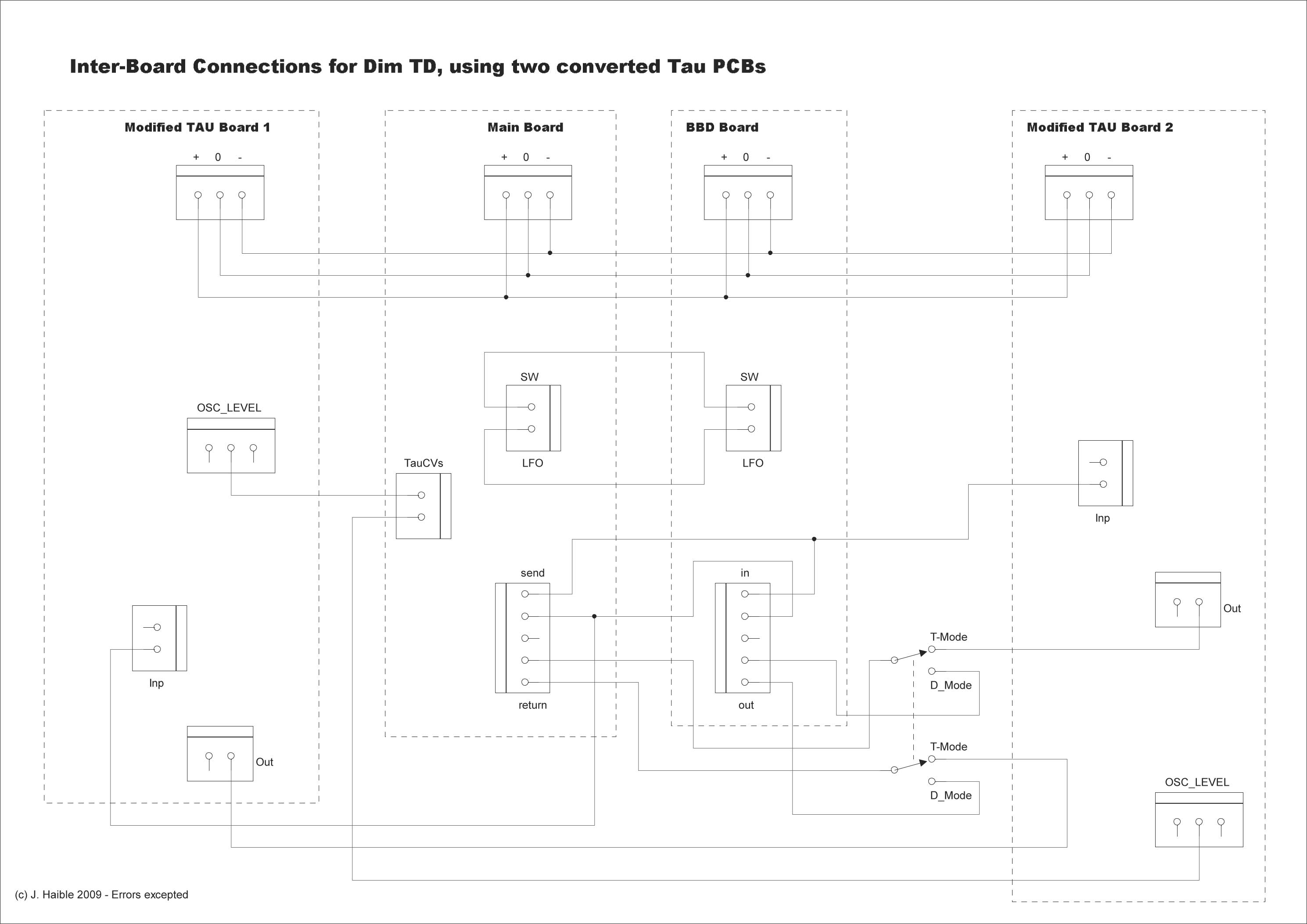
2. Four Board Module Version - ConnectionsNow - you can build this thing with just the BBD Board. This produces the "simple, true-stereo, dual-BBD Chorus with voltage controlled Chorus Rate and voltage controlled Chorus Depth." And You can build it with the BBD Board and the Main Board - to "emulate the famous 'Dim D' sound with it's unique filtering and presets, using two PCBs, the 'Dim D'." Etc, etc, etc. But we're building the completely nutso version with the two Tau Pipe boards. Here's how Jürgen shows their connections:
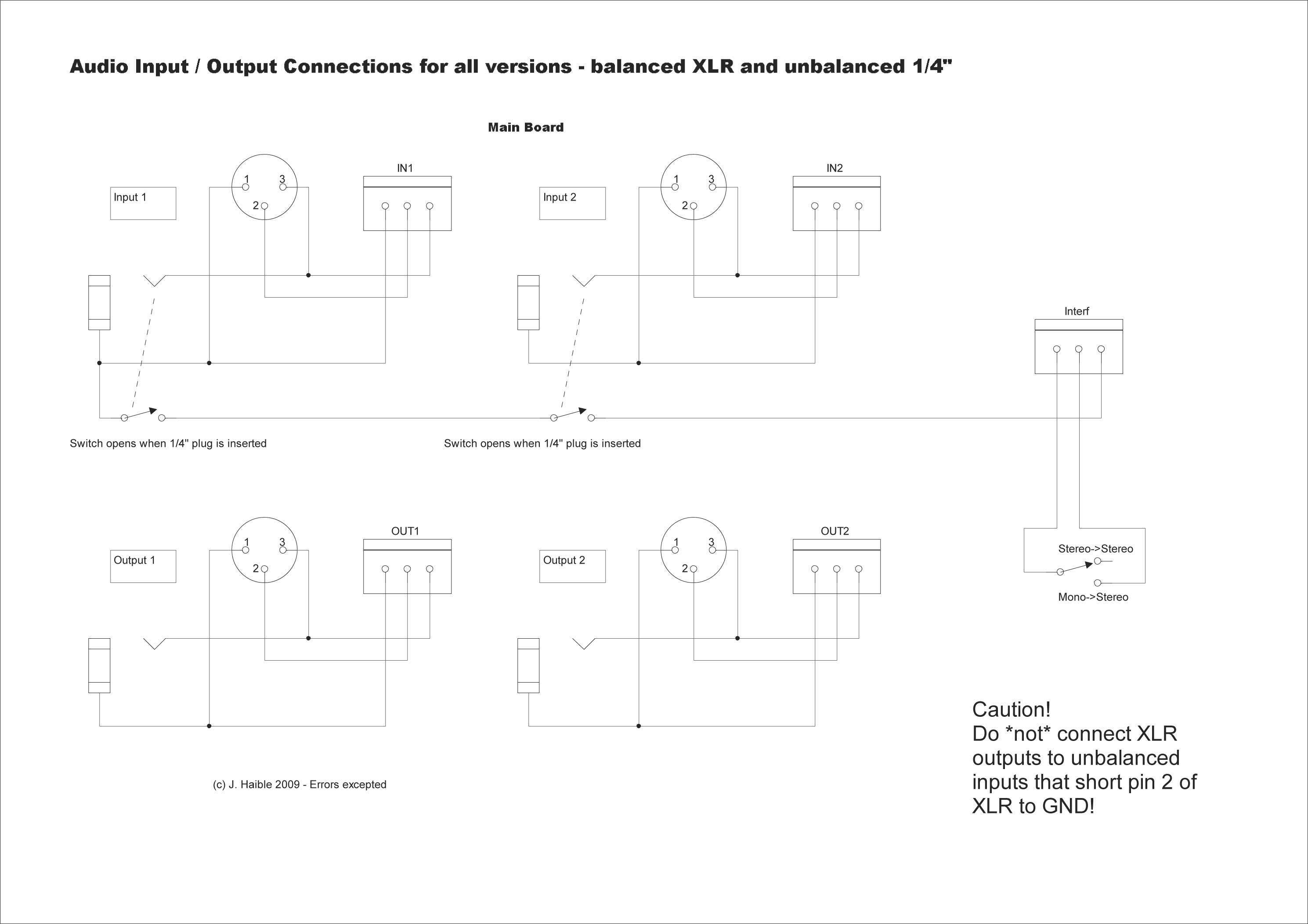
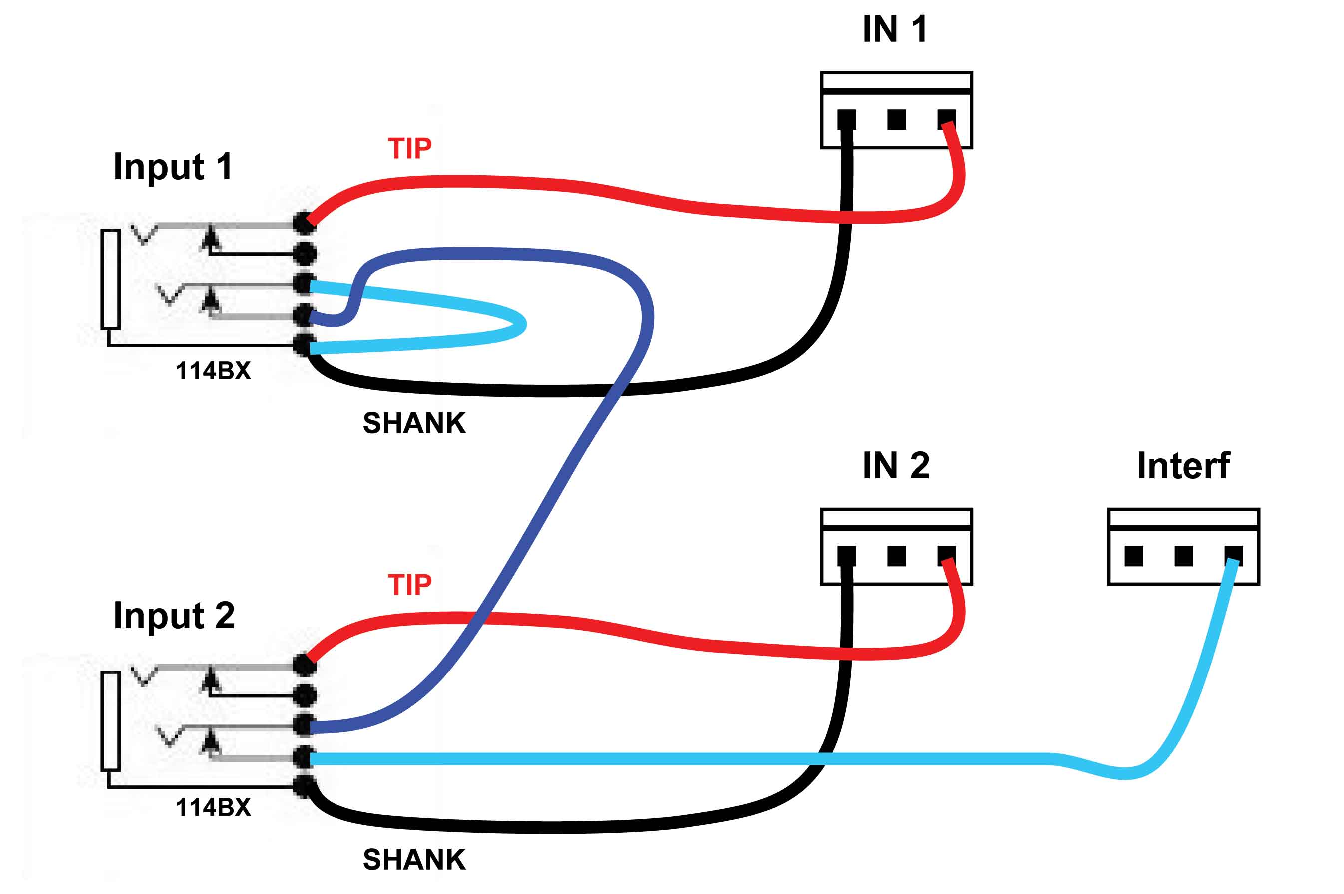
3. Input ConnectionsXLR vs 1/4" Jack You can build the module with XLR balanced inputs and outputs. We suppose you could, therefore provide balanced TSR jacks as well. But we're going to build it with regular old unbalanced jacks. Jack ground-side switch This option requires a switch in the ground (shank) side of the jacks. That switch can be accomplished with a 114BX type jack. Stereo / Mono Switch This connection diagram also shows the SPDT Stereo / Mono Switch:
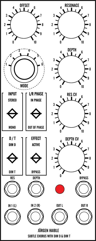
4. ControlsBBD Board LFO Panel Controls Three Controls - completely optional; but we've got space on the panel
FREQ - 100K lin - shown as "Offset" on the BBD PCB schematic diagram. BBD Board LFO CV Controls These Trim the CV inputs - again, completely optional; but there's space
RES CV - 100K lin - in series with the "Resonance CV" input shown on the BBD PCB schematic diagram. Switches These Trim the CV inputs - again, completely optional; but there's space
INPUT Mono/Stereo - DPDT - switches between Mono vs Stereo inputs as shown on hookup diagram. |
||
Parts |
||
|
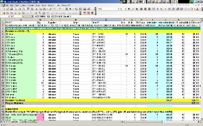
Will and I have developed a parts-list / bill-of-materials in the form of an XL spreadsheet. Jürgen has been very patient and helpful answering our many pesky questions. In the BOM, the left-most column is the "part." These parts we have a high (but not perfect) level of confidence that we've specified correctly - we caught a mistake or two in part numbers / prices as we were ordering. please double-check us and let us know of mistakes you find. Click here to see Jürgen's Bill of Materials. Corrections to BOM: None yet - Notes: None yet - Click here to download the spreadsheet (apx. 350K).
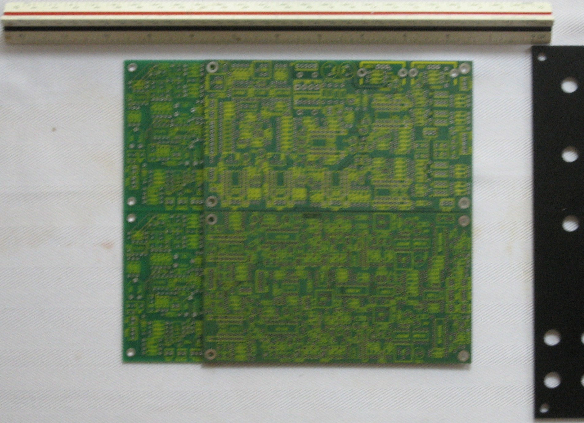
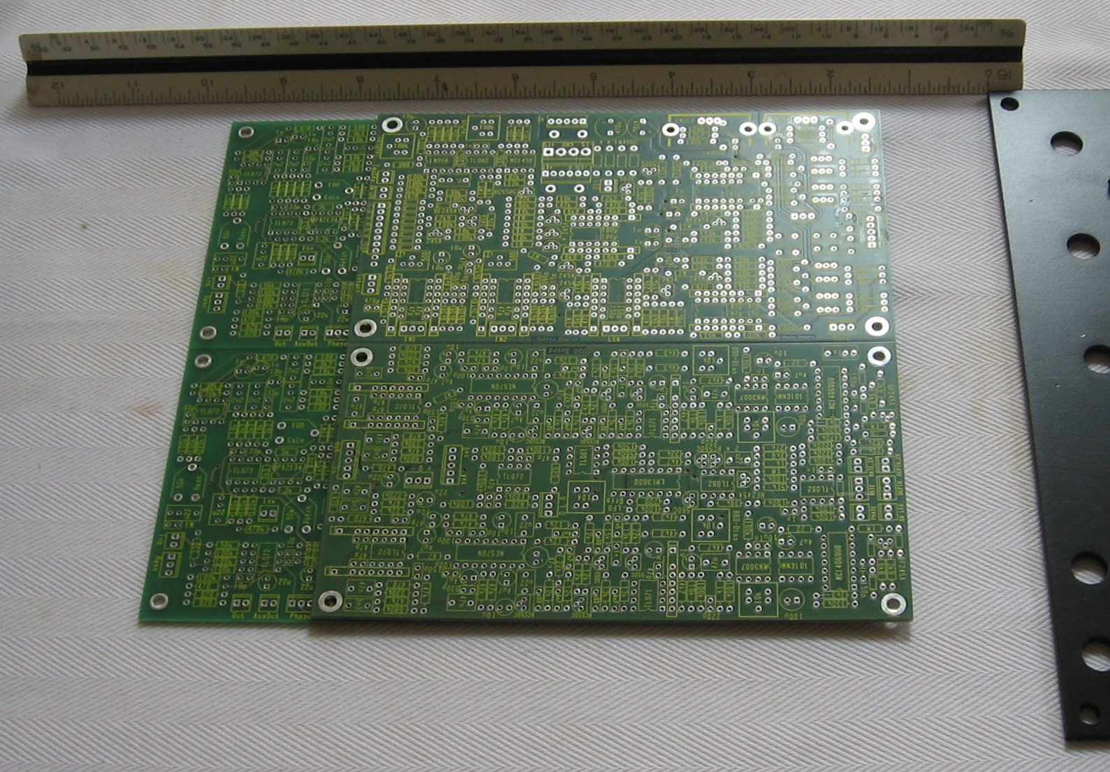
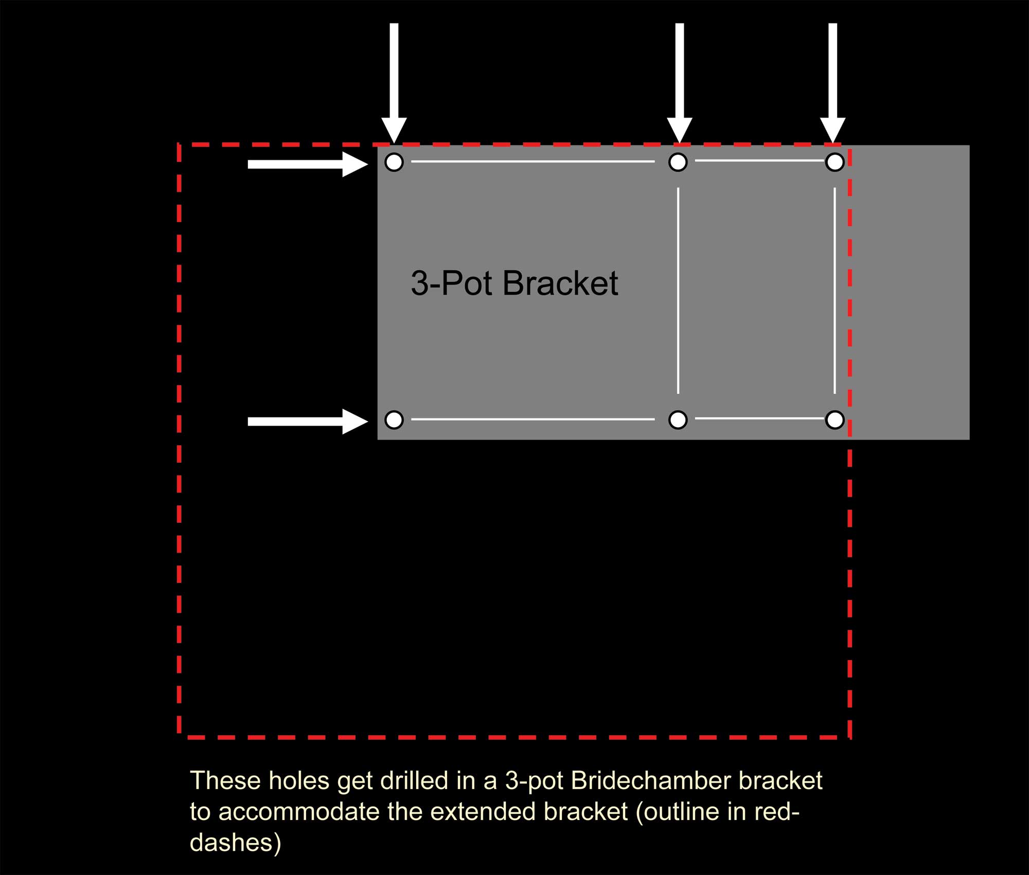
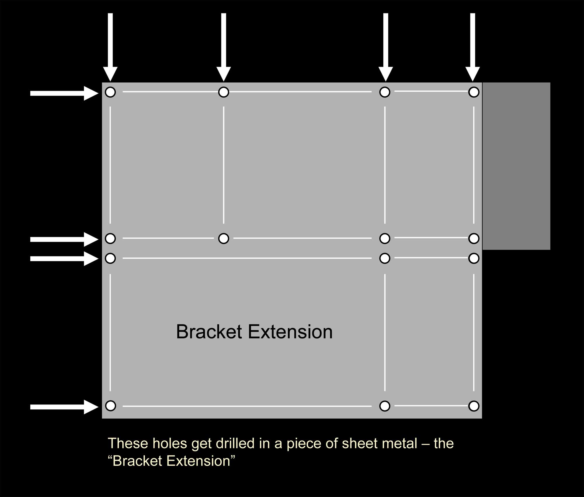
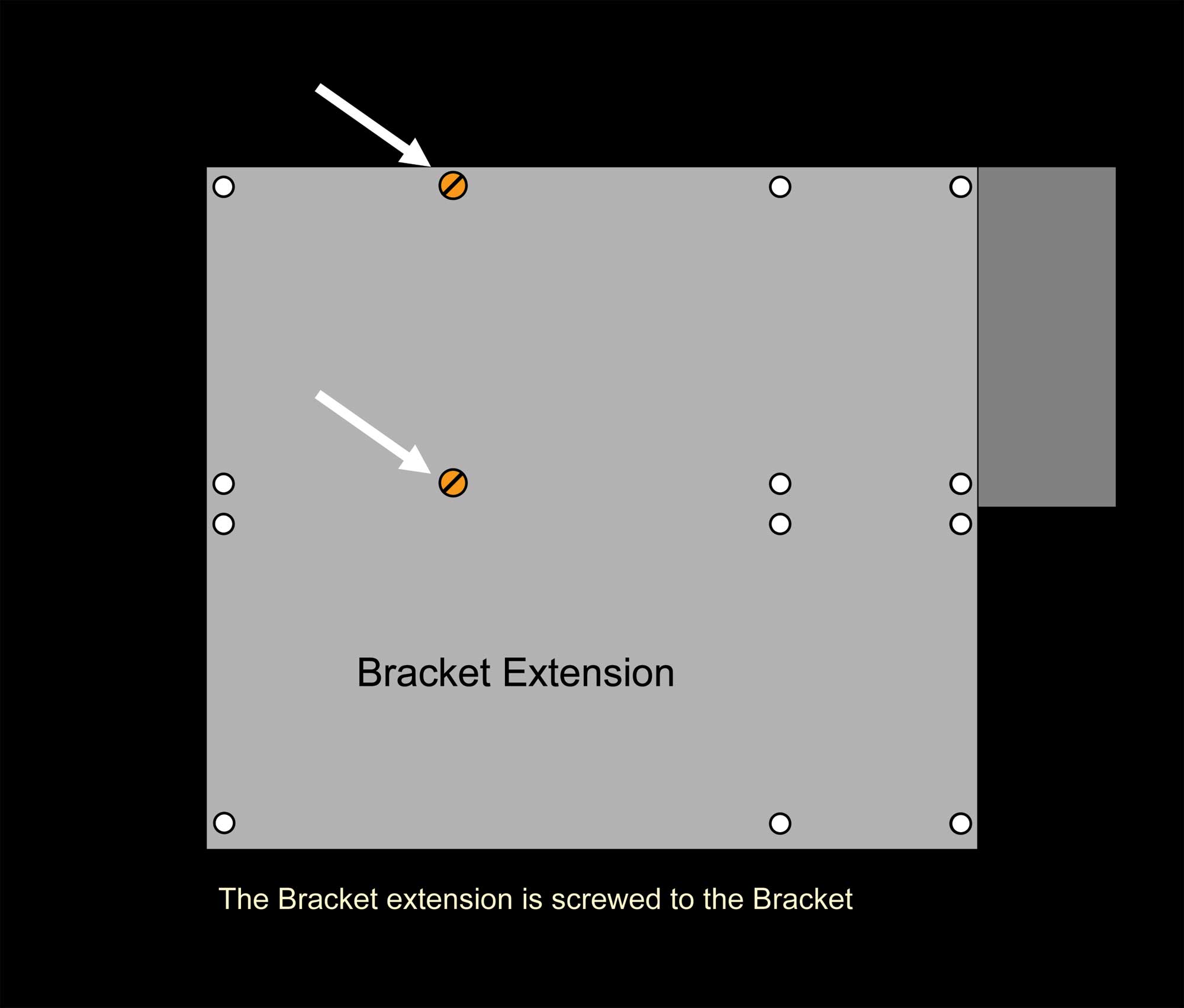
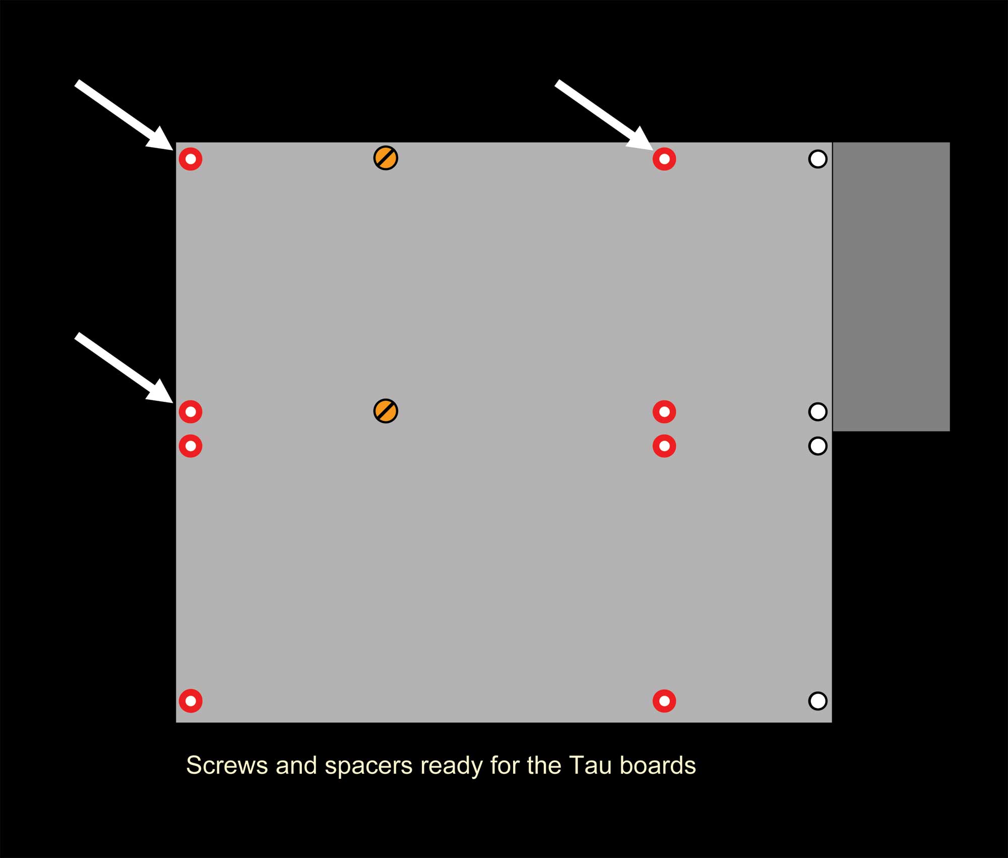
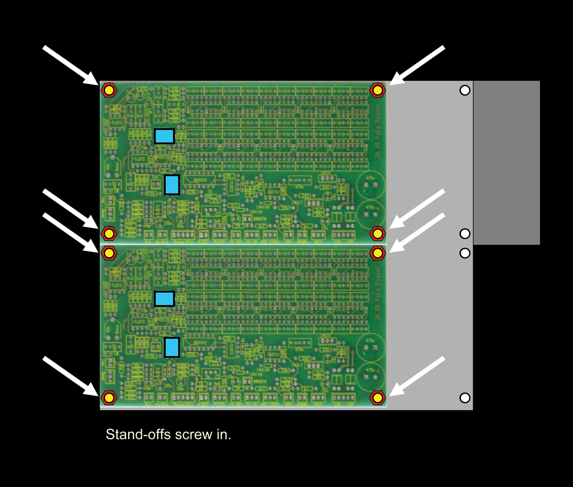
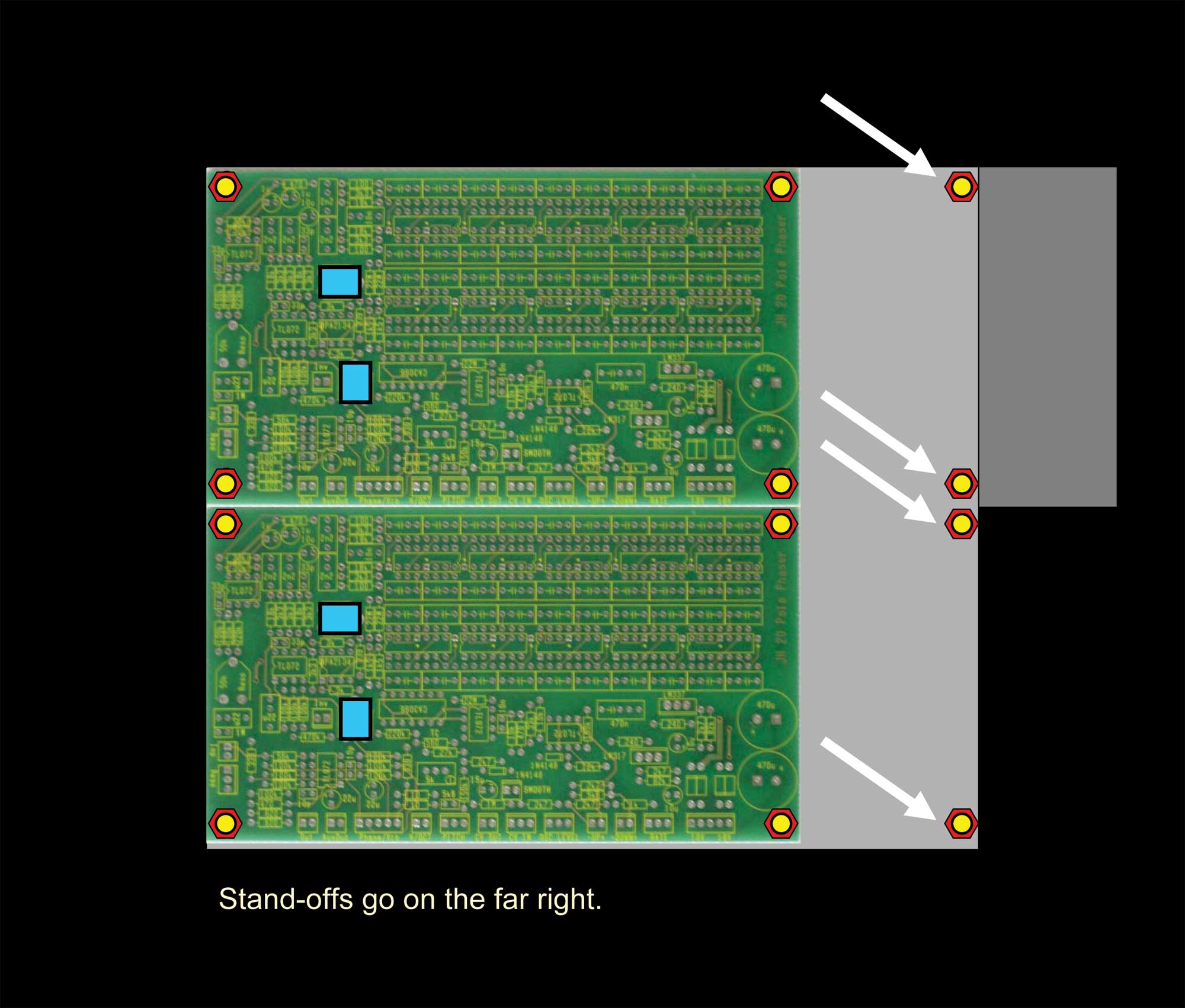
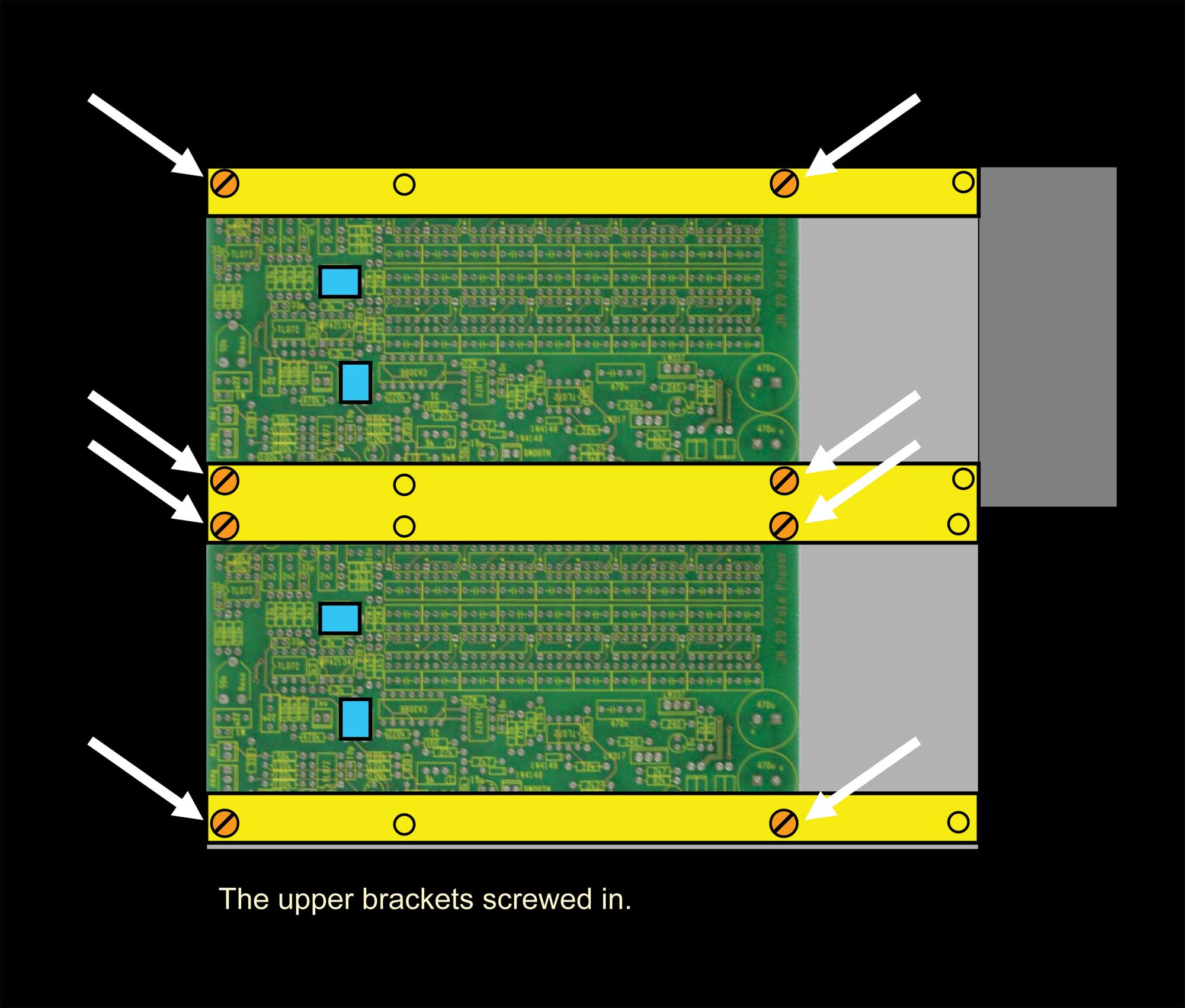
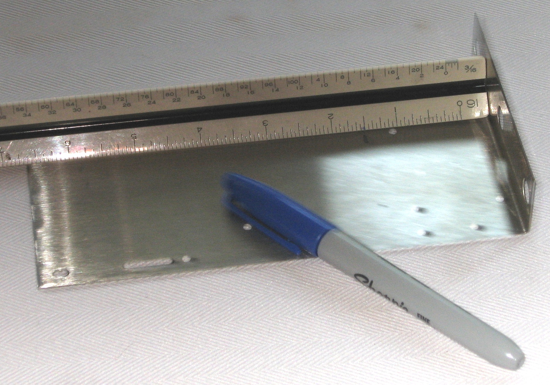
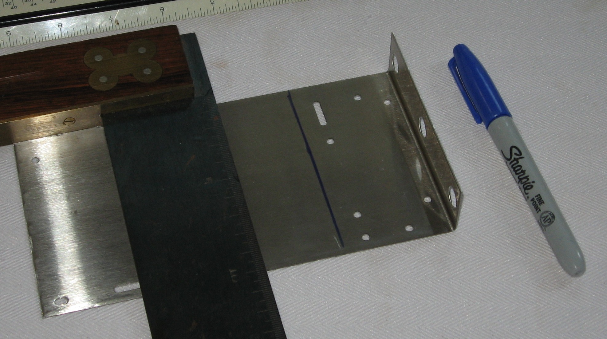
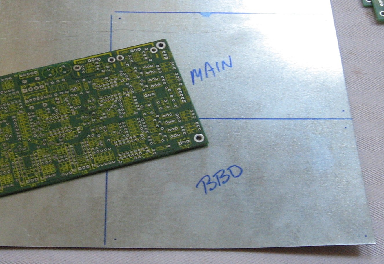
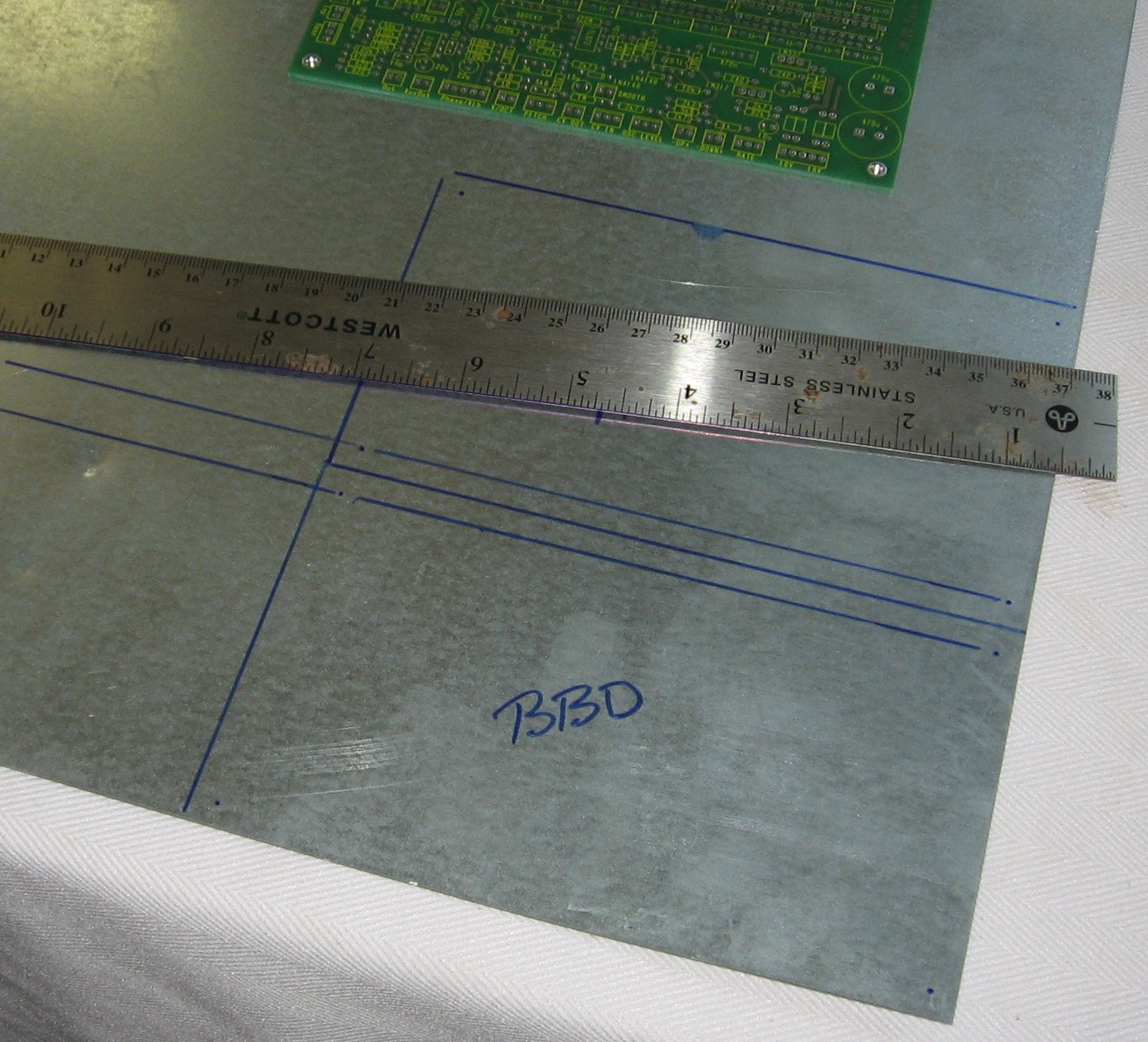
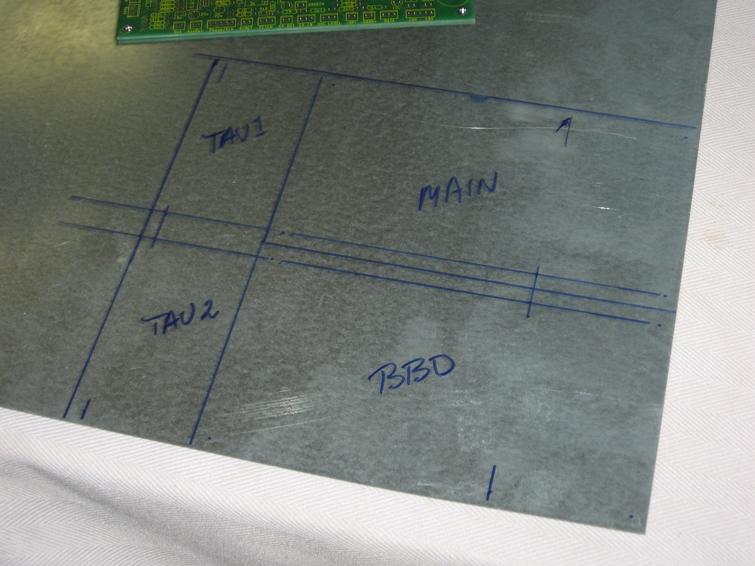
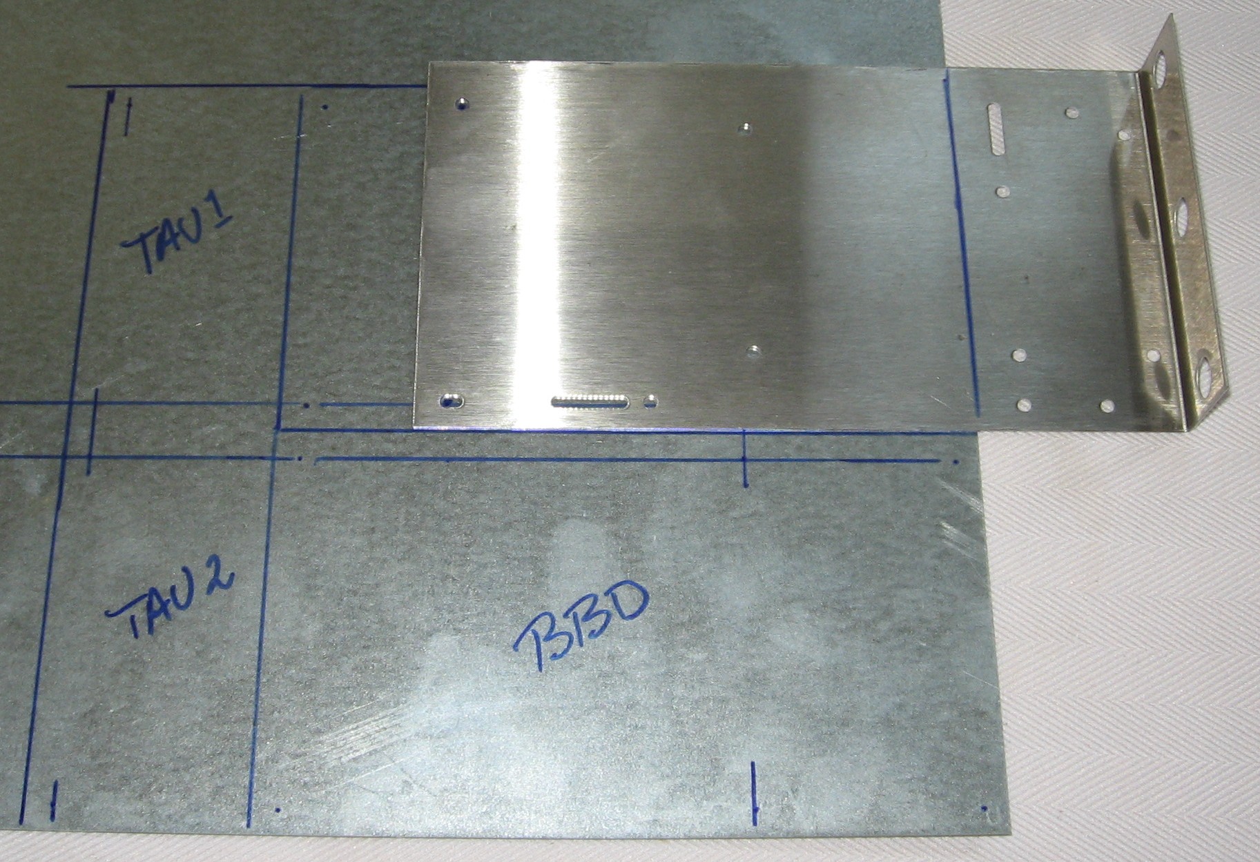
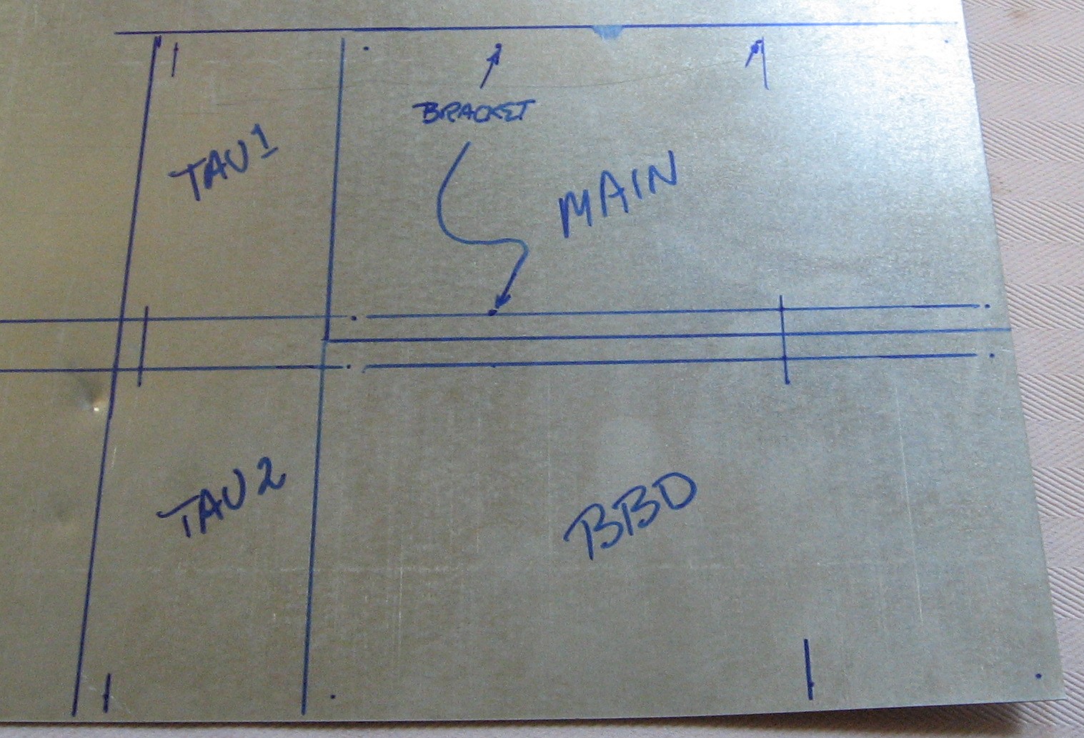
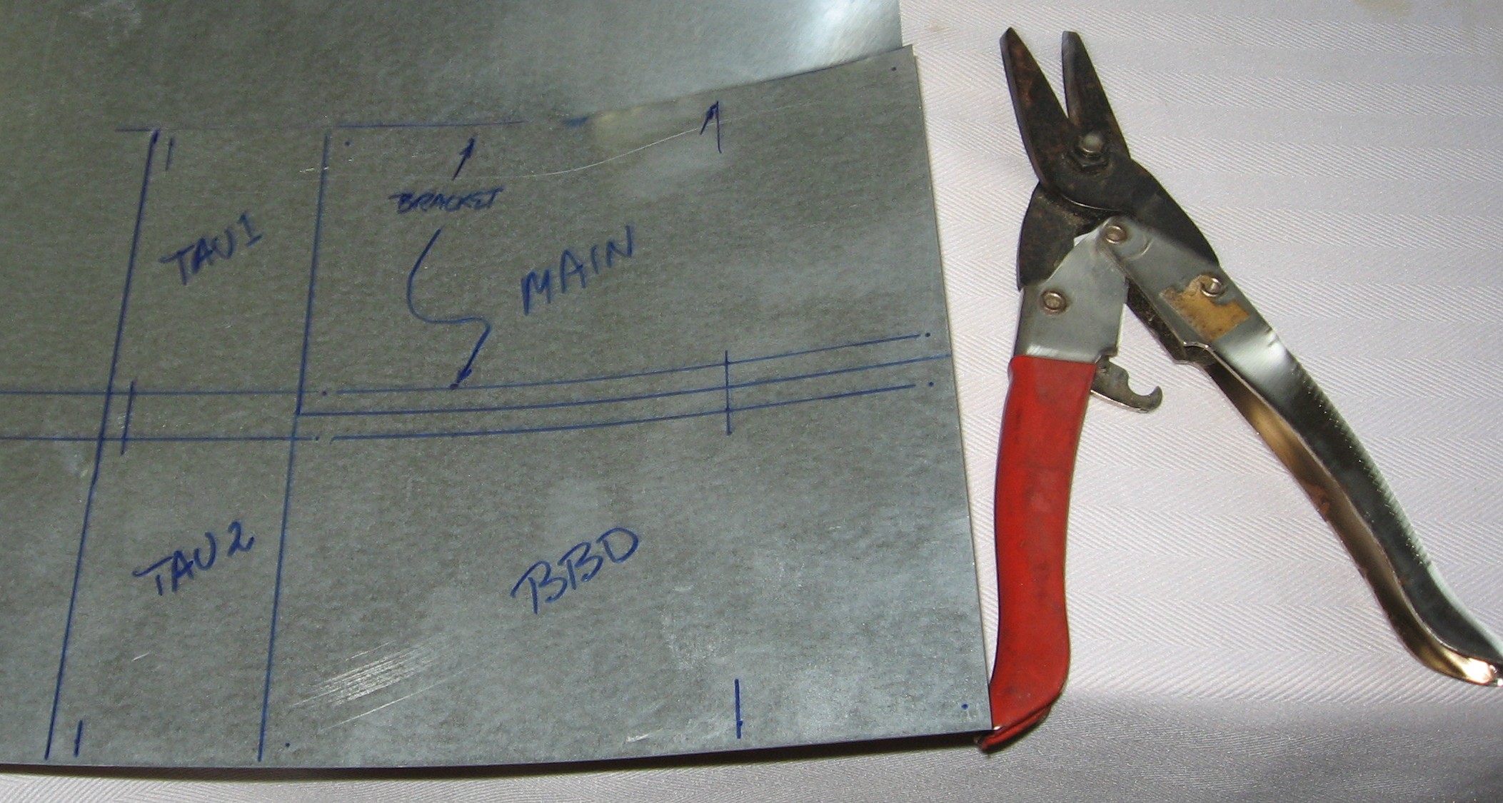
Mounting Bracket In order to arrange the four PCBs behind the panel we/ll need to create a supplemental bracket to attach to a Stooge 3-pot Bracket.
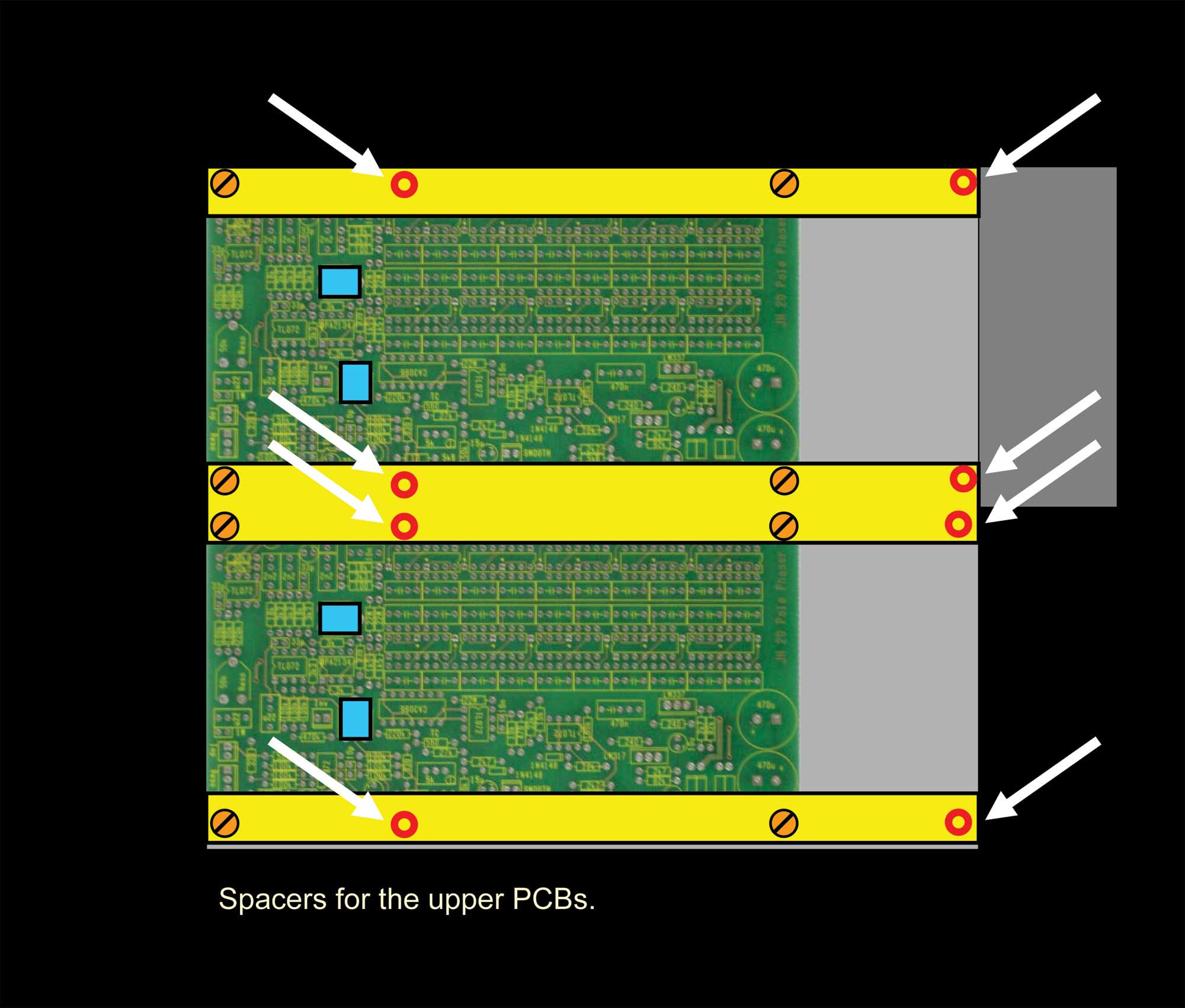
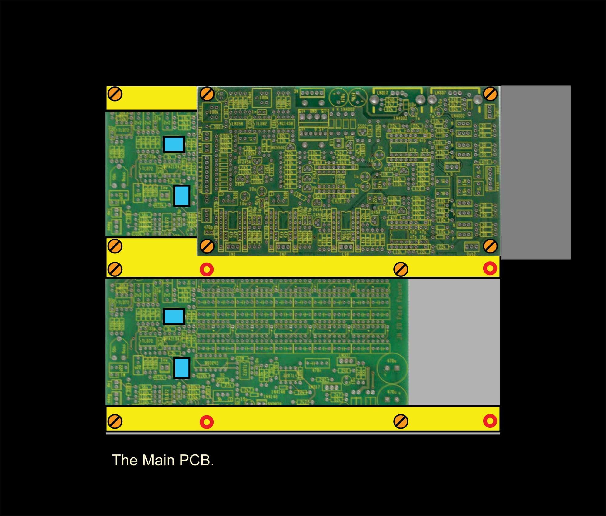
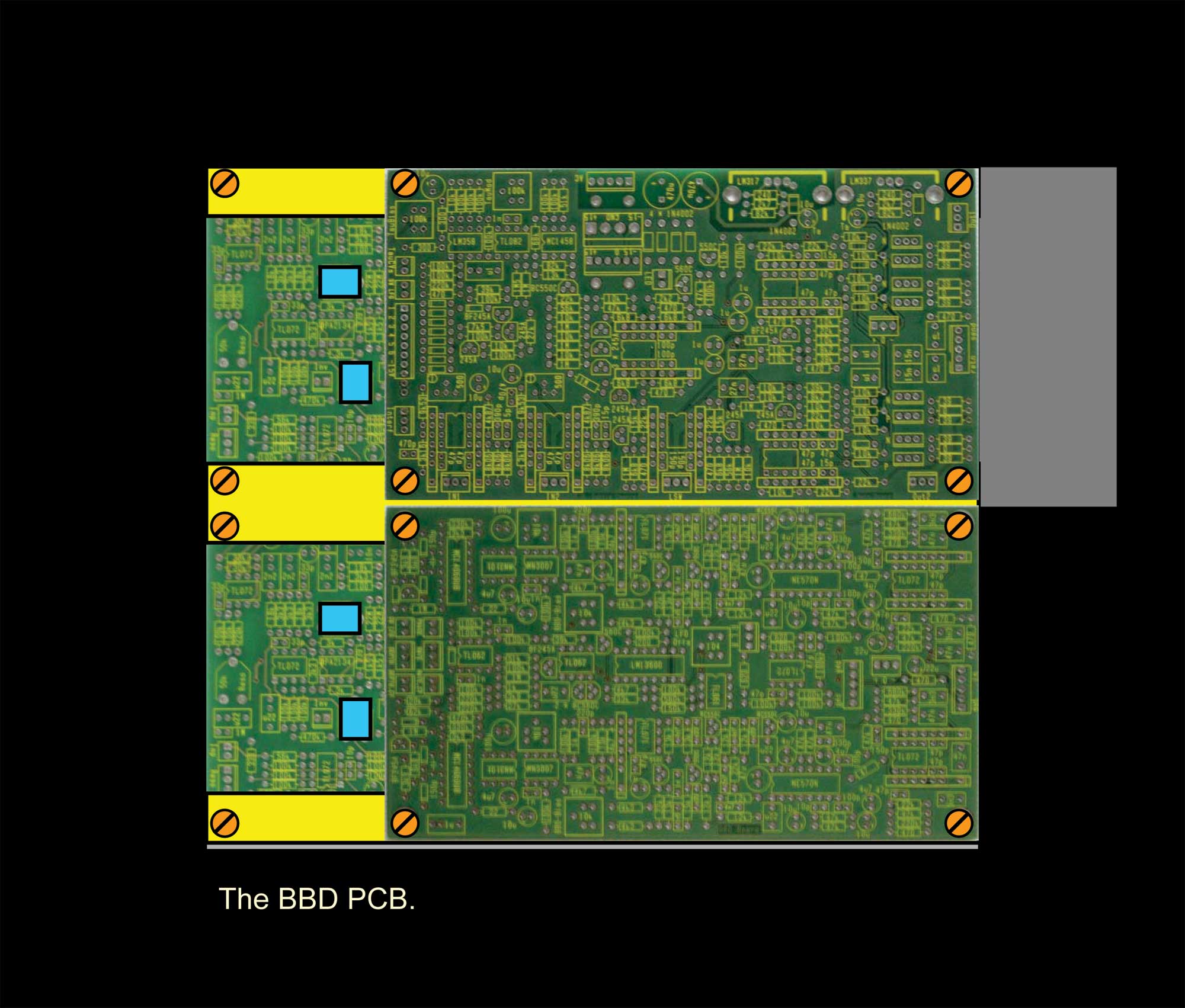
To access all the adjustment trimmers, we'll arrange the boards in two layers like this - with the Tau boards below the BBM and Main Boards - but extending beyond - so the two trimmers on the Tau boards are accessible. They'll take up about 9-3/4 in. depth and we'll create supports for the two top pcbs.
Here's how we'll do it:
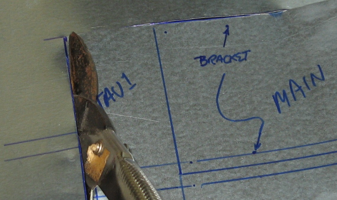
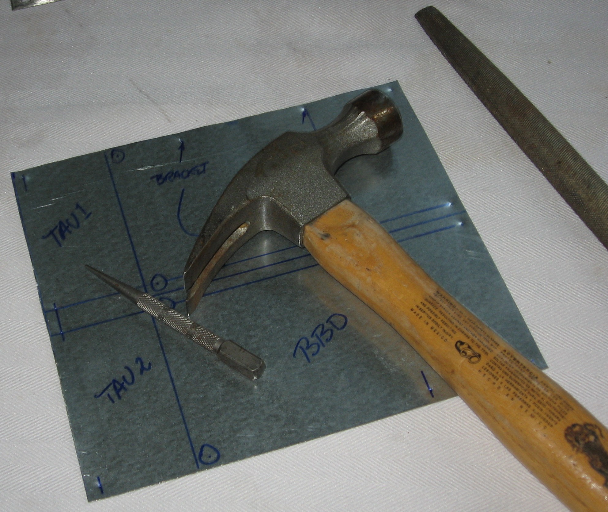
We got some 26 gauge sheet steel at Home Depot and began:
|
||
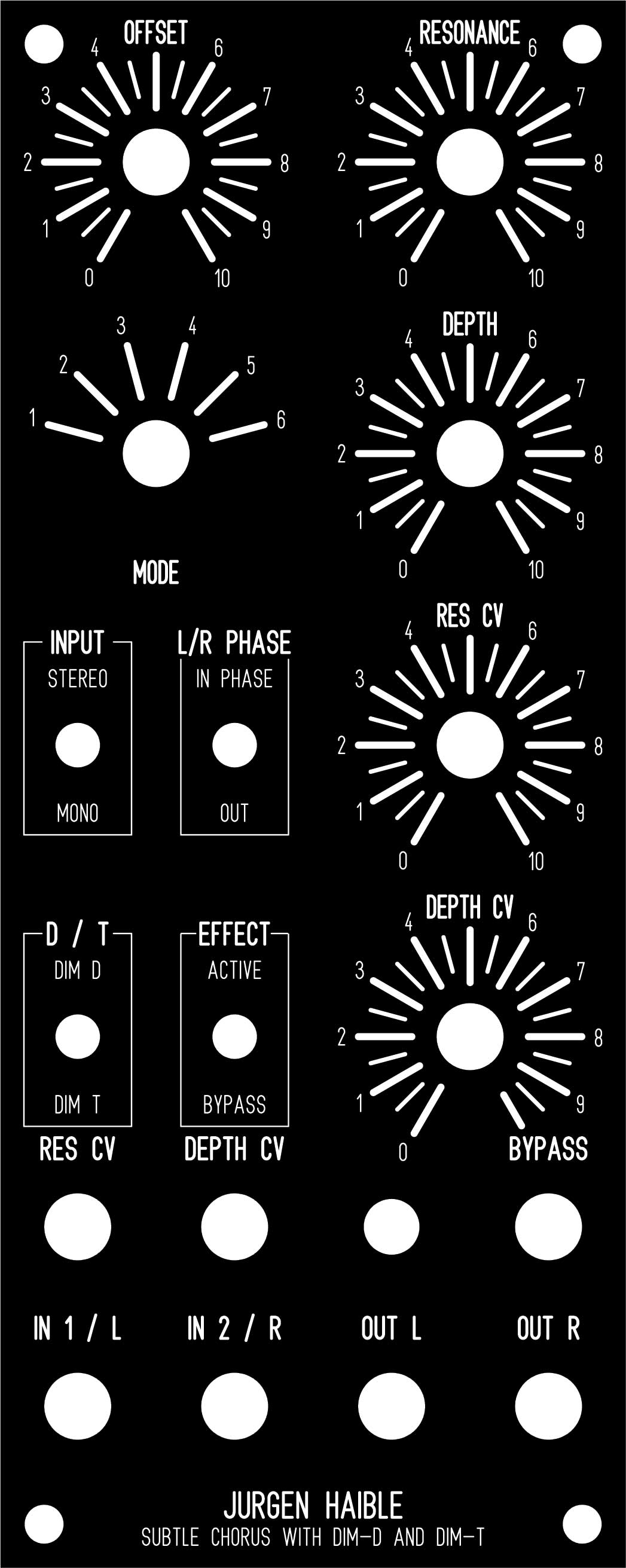
Panel
For our FPD panel design, click here.
|
||
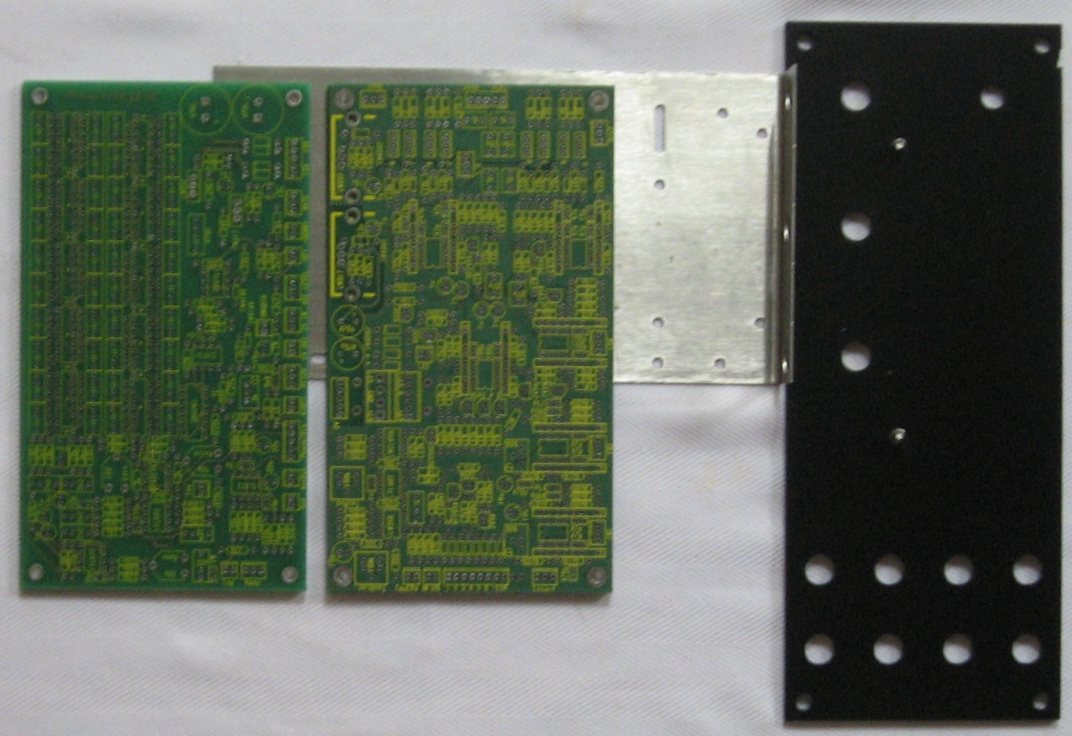
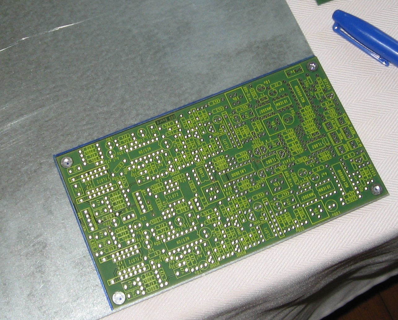
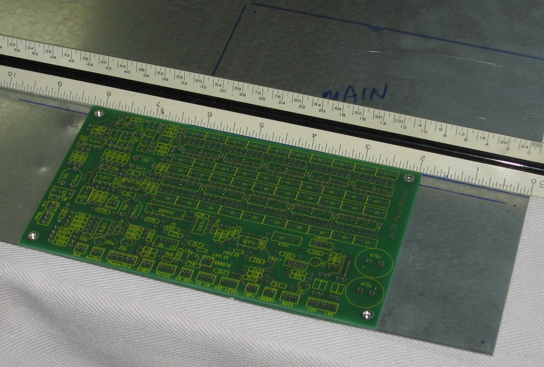
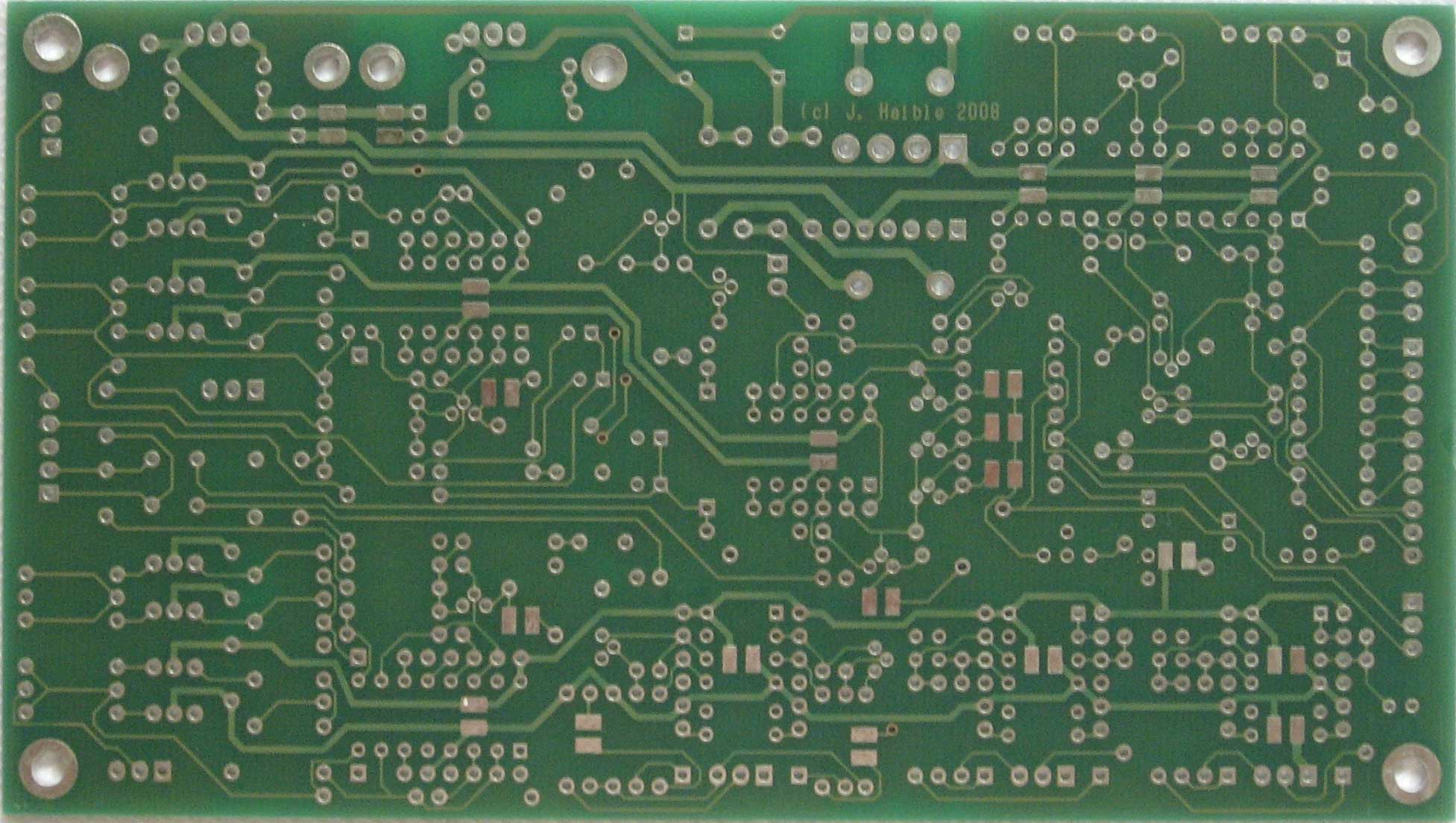
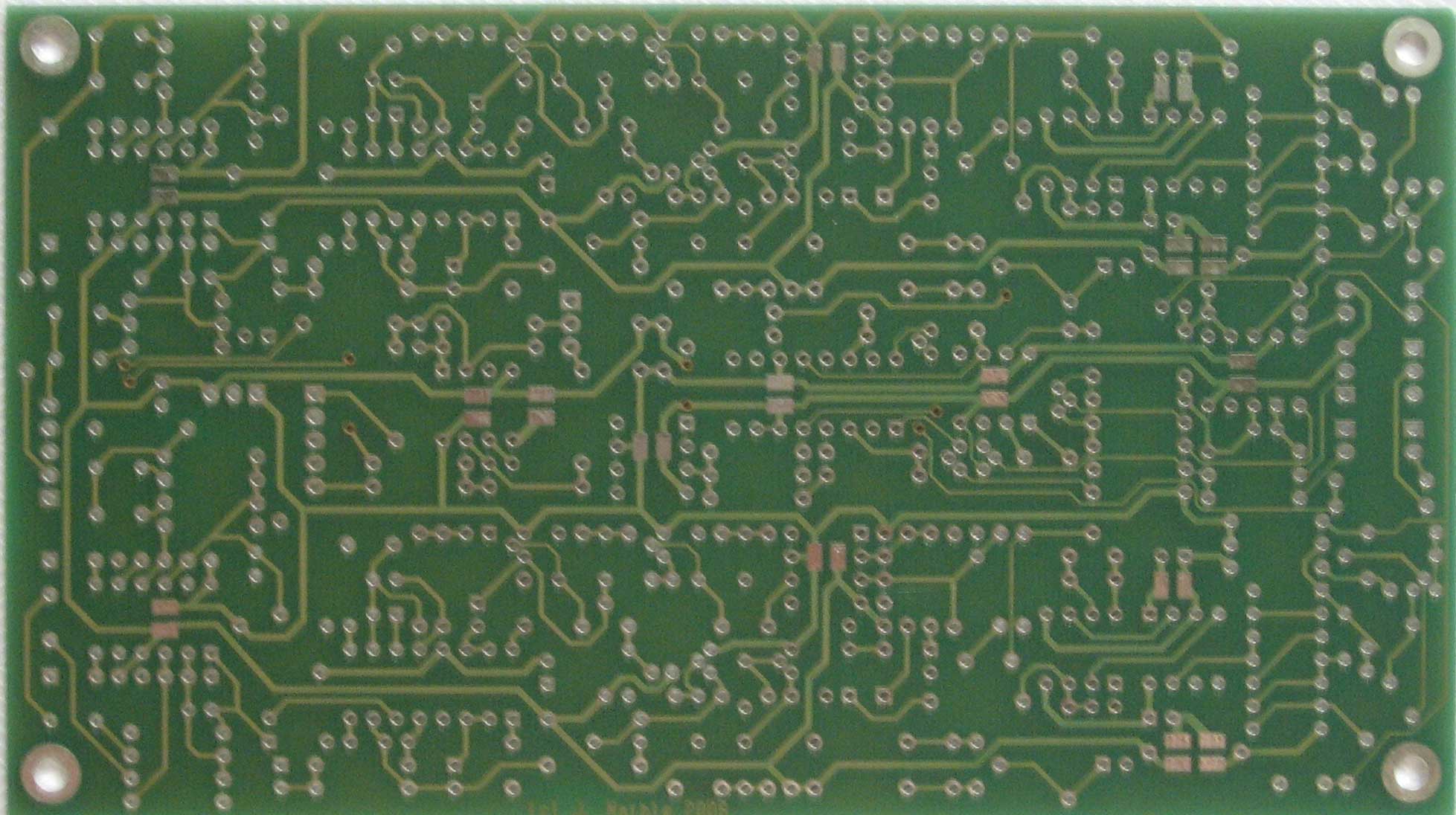
PCBsAgain, here are the PCBs:
|
||
Construction Phase 1All the stuff in Phase 1 gets soldered using "Organic" Solder. At every break in the action, we wash the board off to get rid of the flux. |
||
|
Resistors |
||
|
Capacitors |
||
|
IC Sockets |
||
Construction Phase 2All the stuff in Phase 2 gets soldered using "No-Clean" Solder and the PCB doesn't get washed off from here on. |
||
|
SMT caps / TL071 fix jumpers |
||
|
ICs and Trimmers |
||
|
Mounting Bracket |
||
|
Test Mount |
||
|
PCB Wiring |
||
|
Bracket mounting |
||
|
Bypass Switch |
||
|
Output Jacks |
||
|
Input Pot |
||
|
Rotary Switch |
||
|
Knobs |
||
|
Construction Done |
||
Set up / Testing |
||
Use Notes |
||
|
|
||
|
The fine Print: Use this site at your own risk. We are self-proclaimed idiots and any use of this site and any materials presented herein should be taken with a grain of Kosher salt. If the info is useful - more's the better. Bill and Will © 2005-2011 all frilling rights reserved
|