Bill and Will's Synth
|
Table of Contents |
|
This page has become really long, so here's a table of contents that we hope will make it easier to traverse: Background - presents an explanation and Jurgen's initial description of the effect Recapitulation of Construction/Feature Options - presents a simple list of the different possible implementations Parts - presents a Bill of Materials and notes about it Panel - presents how we, in collaboration with Jürgen and others, came up with our panels' design - ultimately Scott Deyo at Bridechamber fabricated the MOTM format one Construction Phase 1 - Resistors, Capacitors, IC Sockets, Power Plugs, MTA headers Construction Phase 2 - Trimmers - OK, this is where we've left off for now |
Background |
|
What's a Frequency Shifter? Hallgeir Hellands describes it like this: ..."Not to be confused with the Pitch Shifter, which shifts your pitch preserving the harmonic structure in the signal; the Frequency Shifter shifts your signal preserving the frequency structure. Neither to be confused with the ring modulator, which produces both sum and difference frequencies from the original signals; the Frequency Shifter gives you separate sum and difference signals. Confusing? Probably others can explain it better. "For me, the most useful and beautiful effect is the slow phasing like sound produced when we use a very low-frequency modulation (near zero hertz) - and especially in stereo, with up and down shifted signals fed to seperate channels." ..."I should try to explain what is happening inside the box. I will assume that you know how a ring modulator works. (basically a ring modulator multiplies two voltages - if you give it two sine curves of different frequencies, the ring modulator will produce the sum and difference frequencies.) There is inside the FS-1 a very interesting little oscillator called the Quadrature oscillator. It produces two sine waves of the same frequency but one is phase shifted 90 degrees compared to the other. Sine and Cosine, basically. The input signal also needs a 90 degree phase shifted counterpart, this is done by pushing it through a dome filter - two strings of filters that will give us two signals where one is shifted 90 degrees compared to the other. Sine and Cosine again. Then the two Sines are multiplied (the oscillator signal and the input signal) and same for the Cosine pair. Now we have two signals: one is carrier Sine multiplied by signal Sine, and the other is carrier Cosine multiplied by signal Cosine. Now when we sum and difference these two signals we get up-sifted and down-shifted output signals. "An interesting thing is the ability for the modulation oscillator to go through zero. This is because the 90 degree phase shift signifies a direction. So by inverting one of the two (either the Sine or the Cosine) you will get a reverse direction carrier signal, which means that we shift the other way. "Another interesting thing is that if you frequency shift something down, then the bass frequencies will come up on the "other side" before the treble frequencies, and therfore they will be on top. So by shifting down you will basically flip the frequency spectrum upside down." On his site, Hellgeir has some great illustrative sound clips. Jürgen's site describes the effect thus: "About 10 years ago I started to build a frequency shifter with the goal to have similar sound quality as the Moog / Bode frequency shifter. ..."I've chosen a slightly different approach than the famous Moog / Bode model: Instead of using a beat-frequency oscillator, I implemented a linear and exponential-controlled Quadrature-Thru-Zero VCO directly. This covers the whole audio range, and (unlike the Moog / Bode) goes down far into the sub-audio range, such that you can run it with something like 1 cycle in 10 seconds, for slow "Barberpole Phasing". Also, I've chosen a different approach for the noise reduction. Every Frequency shifter has to battle carrier bleed-thru. In the new version, I have implemented a second-order trimming which, beyond nulling the carrier in the output, also allows to suppress the quadratic term, which means cancelling the bleed-thru at twice the carrier frequency. Even with so much effort going into the carrier suppression, you want complete silence at the output when no input signal is present. Moog used a "Squelch" circuit for this, which is basically a noise gate, and needs manual adjustment of the threshold, depending on level and nature of the input signal. I am using a special Compander / Downward-Expander system, similar to the one found in the Roland VP330 Vocoder Plus (All opamps and OTAs, NE570 etc.!), slightly changed to fit the needs of a frequency shifter." |
|
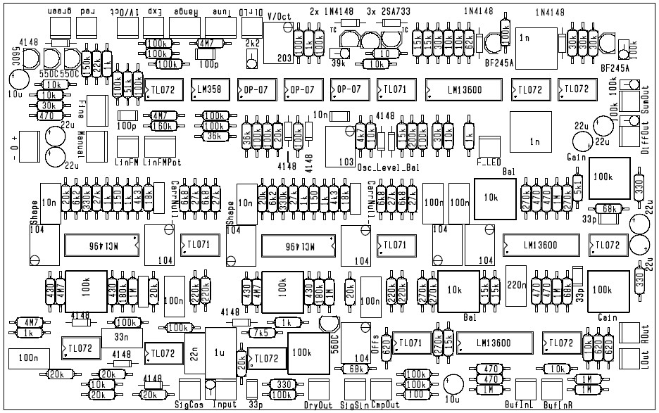
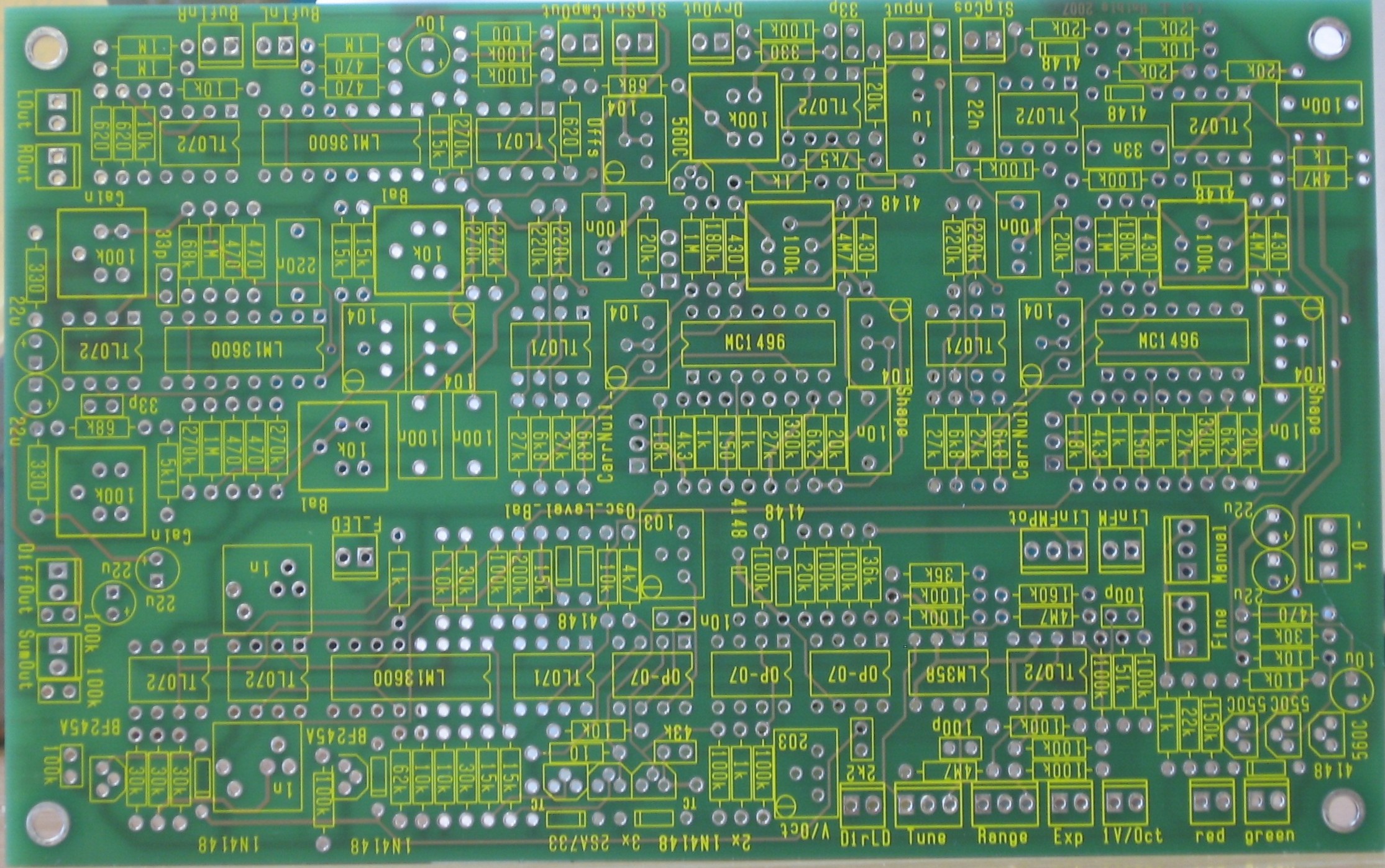
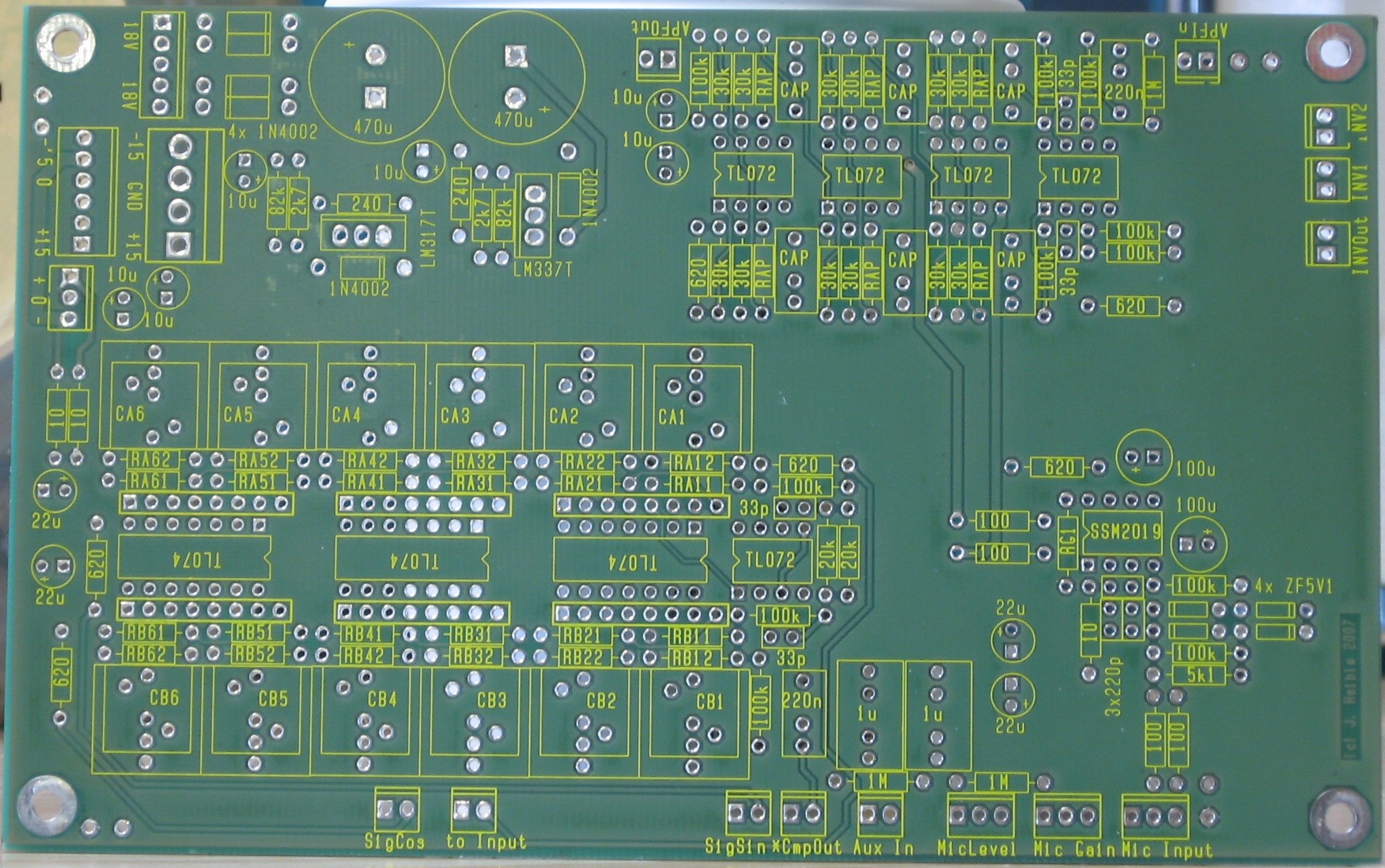
Jürgen's design uses two PCBs. "The whole circuit fits on two 160mm x 100mm sized boards:" Board 1 contains the Quadrature-Thru-Zero-VCO, the Ring Modulators, Summing Amps and Compander Circuit.
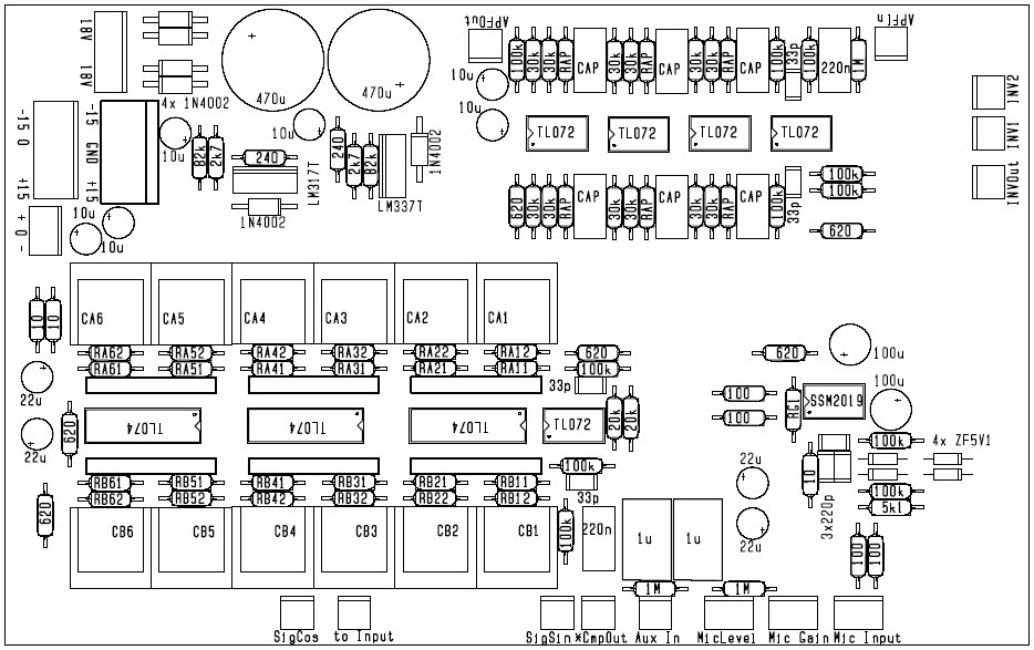
Board 1 diagram - you can click on the image to download a higher resolution image. Board 2 contains the Dome Filter, a Microphone Preamp, an extra 6-pole All Pass Filter for Barberpole Phasing, an Inverter for CV inversion, a Power Supply that only needs a transformer and fuses to be connected, as well as MOTM and Synthesizers.com system connectors for direct +/-15V power supply.
Board 2 diagram - you can click on the image to download a higher resolution image. |
Recapitulation of Construction/Feature Options |
|
1. The only real construction options for the FS1A are porwer supply options: Option 1 - On-board power supply. Option 2 - MOTM-style dual power supply. |
Option Details |
|
1. Power Supply Option 1 On-board power supply - per Jürgen, "It contains a power supply (less transformer and primary fuse). You only have to connect 18V AC from a transformer." Option 2 MOTM-style dual power supply - |
Parts |
|
Will and I have developed a parts-list / bill-of-materials in the form of an XL spreadsheet. Jürgen has been very patient and helpful answering our many pesky questions. As of today, 12 May 2008, it's almost complete. In the BOM, the left-most column is the "part." The parts we've ordered have a green background. These parts we have a high (but not perfect) level of confidence that we've specified correctly - we caught a mistake or two in part numbers / prices as we were ordering. please double-check us and let us know of mistakes you find. Click here to see Jürgen's Bill of Materials. Corrections to BOM: None yet - Notes: None yet - Click here to download the spreadsheet (apx. 350K).
|
Panel |
|
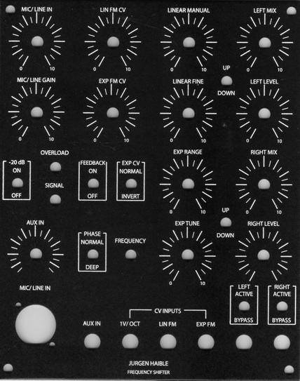
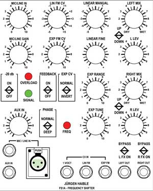
With the help of Jürgen and in collaboration with and with input from Mike (mrmike of clickbang) and Scott Deyo (Bridechamber.com), Will and I developed the Panel design at the top of the page. If you click on that drawing, you can see a bigger version. The evolution of the design isn't really worth exploring. The design went back and forth between us and Jurgen several times - each time he was clarifying how the features should be interpreted.
|
Construction Phase 1All the stuff in Phase 1 gets soldered using "Organic" Solder. At every break in the action, we wash the board off to get rid of the flux. |
|
|
Construction Phase 2All the stuff in Phase 2 gets soldered using "No-Clean" Solder and the PCB doesn't get washed off from here on. |
Set up / Testing |
Use Notes |
|
|


|
The fine Print: Use this site at your own risk. We are self-proclaimed idiots and any use of this site and any materials presented herein should be taken with a grain of Kosher salt. If the info is useful - more's the better. Bill and Will © 2005-2011 all frilling rights reserved
|