Bill and Will's Synth
|
||
Table of Contents |
||
|
This page has become really long, so here's a table of contents that we hope will make it easier to traverse: Background - presents an explanation and Ian Fritz's initial description of the Module Modifications - presents details of Dave Brown's modifications for 15V operation and improved triangle symmetry Parts - presents a Bill of Materials and notes about it Panel - presents the MOTM format panel Construction Phase 1 - Resistors, Capacitors, IC Sockets, Power Plugs, MTA headers Construction Phase 2 - Trimmers, Panel connections |
||
Background |
||
|
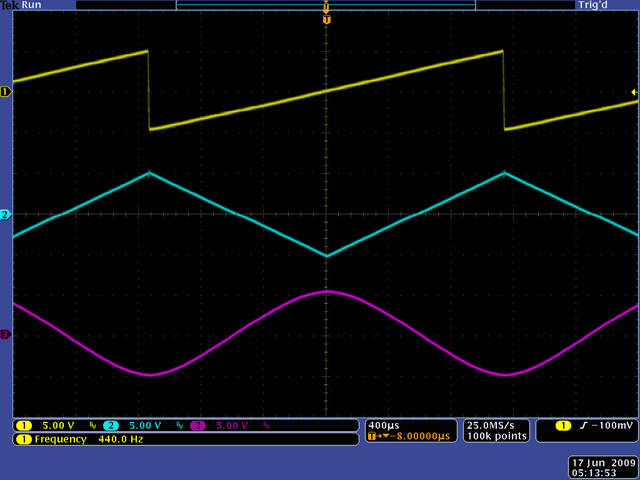
Ian Fritz - January 2009: "This module is a sawtooth-based VCO capable of frequency modulation (FM) extending past zero frequency into the negative-frequency regime. Thru-zero FM provides a much wider and richer variety of sounds than “ordinary” (positive frequency only) FM. "The negative-frequency version of a waveform is simply a time-reversed replica of the original waveform. When a VCO is modulated through zero frequency, the waveform slows down to a stop and then speeds back up in the reverse direction. "The Teezer’s output waveforms also include triangle and sine waves, for producing sounds with fewer high harmonics, as typically used for bell sounds, train whistles, and so on. The unit also features a variable synchronization control that can be adjusted over a range of settings from hard sync to a fairly loose soft sync. The module can also serve as a highly accurate and stable “ordinary” VCO (i.e., without the deep FM), with upramp, downramp, triangle and sine output waveforms." OK, but what does this mean? A. Sawtooth-based Well... the Teezer has three outputs each for a different wave shape; SAW, TRIANGLE, and SINE. These are the three output jacks on the panel. If you put them through an oscilloscope, you can see a representation of these waves. Dave Brown did this on his site:
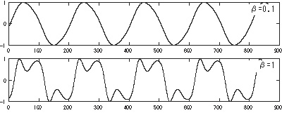
Picture, Dave Brown The top one, the "saw" wave-form is what the Teezer's "core" oscillator is producing. Technically, it's a reverse-saw or ramp wave. The other two wave-forms - the "triangle" and "sine" waves - are being produced from the saw wave by the Teezer's "wave-shaper" circuit. Hence, the Teezer is "sawtooth-based." By the way, Dave's measurement shows the wave-shaper creating opposing peaks of the triangle and sine waves. B. Frequency Modulation Wikipedia: "In audio and music frequency modulation synthesis (or FM synthesis) is a form of audio synthesis where the timbre of a simple waveform is changed by frequency modulating it with a modulating frequency that is also in the audio range, resulting in a more complex waveform and a different-sounding tone. The frequency of an oscillator is altered or distorted, 'in accordance with the amplitude of a modulating signal.' "
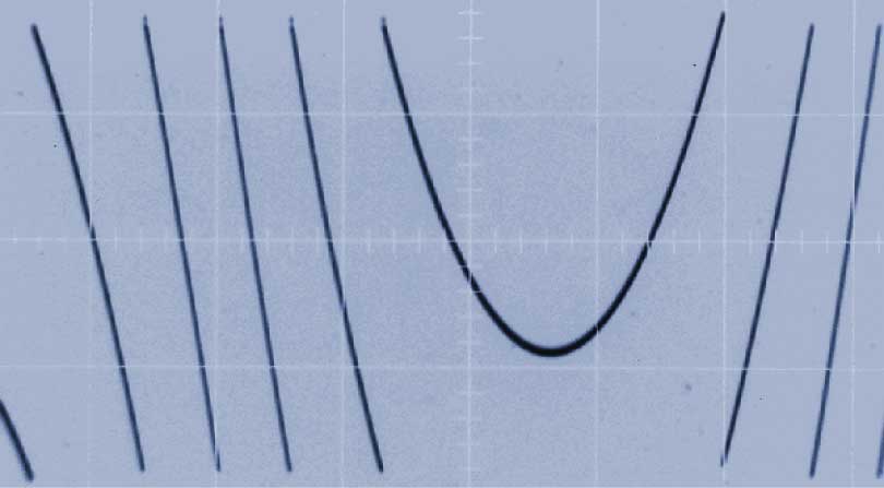
Picture, Wikipedia In the Wiki illustration, above, a 220 Hz "carrier" tone is modulated by a 440 Hz "modulator" tone. In the case of the Teezer, the Carrier Tone would be the output of the Oscillator and the Modulator Tone would be inputted at either the EXP FM or the LIN FM jack. C. "...extending past zero frequency into the negative-frequency regime." Ian Fritz: "Through-zero refers to modulation where the signal frequency goes to zero then reverses sign. What does negative frequency mean? The phase of a wave is freq. x time. (Phase is where you are with respect to the peaks and troughs of the signal.) Therefore, changing the sign of frequency is the same as making time run backwards! So the modulated wave slows down then runs backwards... If the oscillator core could not reverse direction, then the right-hand part of the figure would be flat, from the dip on."
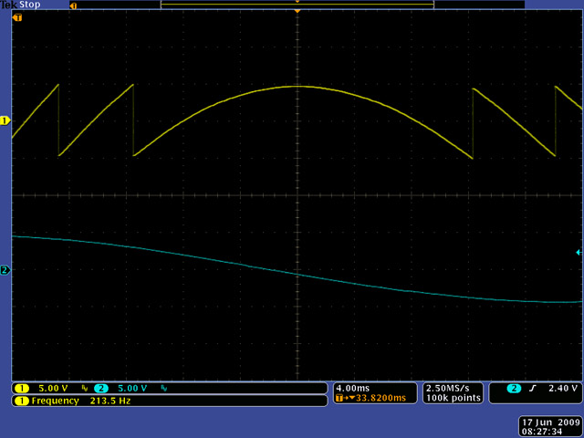
Picture, Ian Fritz Dave Brown: "In a regular oscillator, increasing the linear FM voltage will increase the frequency. Decreasing the linear FM voltage will decrease the frequency. Nothing special happens at 0 volts. The frequency at 0 volts depends on the initial settings of the VCO. Taking the linear FM voltage negative just continues to decrease the frequency. "In a thru-zero oscillator, a negative FM voltage has the same effect as a positive FM voltage except the waveform is reversed. Think of it this way - the absolute value of the linear FM voltage modulates the frequency. The sign of the linear FM input determines the polarity... "Look at the lower waveform which is the linear FM input. When you see zero (at the center) the VCO output is stopped. To the right (e.g. below zero) the waveform is reversed (e.g. was a ramp (positive slope) and now is a saw (negative slope)."
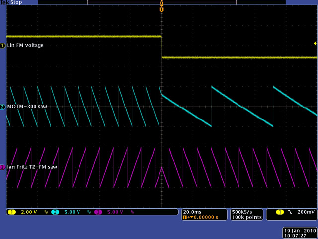
Picture, Save Brown "Connect a MOTM-300 and an Ian Fritz thru-zero oscillator to the same control voltage and same linear FM voltage... As you lower the linear FM voltage, both oscillators decrease in frequency. As the linear FM voltage decreases to 0, the thru-zero oscillator stops while the MOTM-300 produces some frequency. As you decrease the linear FM voltage negative, the MOTM-300 just continues to lower in frequency. The thru-zero VCO now increases in frequency but with an inverted output. That is the significance of the photo..." (above) And in the picture below - "In a conventional VCO, the same positive and negative linear FM voltage produce two different frequencies with the negative FM voltage always producing a lower frequency than the positive FM voltage... "In a thru-zero VCO, the same positive and negative linear FM voltage produces the same output frequency, but the waveform is inverted.
Picture, Save Brown |
||
Modifications |
||
1. 15 Volt Power Supply Mods per Dave Brown |
||
|
Dave Brown writes: TZ-FM Schematics part 1 1. Change R28 from 18K to 27K4 to keep the gate off voltage at -6.3 volts. TZ-FM Schematics part 2 2. Change R116 from 390K to 487K to keep Iabc at 58.4 µA. 3. Change R119 from 22K to 30K to keep a 0 to 3.75 volt range at the negative input of A9a. (I used a 100K potentiometer for R120 so changed R119 to 300K) 4. Change R128 from 47K to 59K to keep the negative input of A10 at 0.65 volts. Probably not required as it keeps the sync reference level at 0.65 volts instead of increasing to 0.81 volts I did not change any other values in the sync circuit. A9 and A10 both operate as comparators with rail to rail output. While the output is higher with 15 volt supplies, the ratio between the R123-R124-R130-R131 and R132-R133 dividers remains constant. TZ-FM Schematics part 3 5. Change R201 and R202 from 1K8 to 2K55 to keep the current at 3.88 mA. Probably not required 6. Change D203 and D204 from 5.1V to 8.2V (1N5237B) to keep the U2 and U3 supply at +/-7 volts. 7. Change D205 and D206 from 3.3V to 6.2V (1N5234B) to keep the A4 supply at +/- 9 volts (on Part 1 this supply is mislabeled as +/-8V) |
||
2. Improve Triangle Symmetry Mod. |
||
|
Dave Brown: "I found that I could improve the symmetry at the top of the triangle by changing C6 to 33 pF. It took some tweaking between the 'Saw symm' and the 'Thresh trim' adjustments to make the triangle peaks match for both the integrator upramp and downramp." |
||
Parts |
||
|
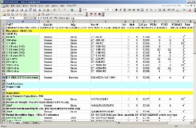
Will and I have developed a parts-list / bill-of-materials in the form of an XL spreadsheet (as usual). After some scrounging, we found everything OK. Please don't take it as gospel. Even so, just now we've used it to make our Mouser and Digikey purchases and we are relatively confident in our specifications.
Click here to download our XL spreadsheet Parts List |
||
Panel |
||
|
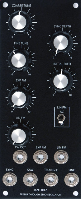
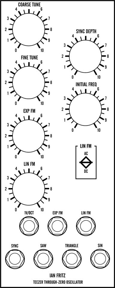
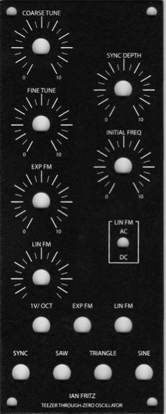
We got ours from Bridechamber:
|
||
Construction Phase 1All the stuff in Phase 1 gets soldered using "Organic" Solder. At every break in the action, we wash the board off to get rid of the flux. |
||
Construction Phase 2All the stuff in Phase 2 gets soldered using "No-Clean" Solder and the PCB doesn't get washed off from here on. |
||
Set up / Testing |
||
Use Notes |
||
|
|
||
|
The fine Print: Use this site at your own risk. We are self-proclaimed idiots and any use of this site and any materials presented herein should be taken with a grain of Kosher salt. If the info is useful - more's the better. Bill and Will © 2005-2011 all frilling rights reserved
|