Bill and Will's Synth
|
Table of Contents |
|
This page has become really long, so here's a table of contents that we hope will make it easier to traverse: Background - presents Thomas White's list of the Module's features Parts - presents a Bill of Materials and notes about it Panel - presents the MOTM format panel Construction Phase 1 - Resistors, Capacitors, IC Sockets, Power Plugs, MTA headers Construction Phase 2 - Trimmers, Panel connections |
Background |
|
Thomas lists the features thus:
|
Parts |
|
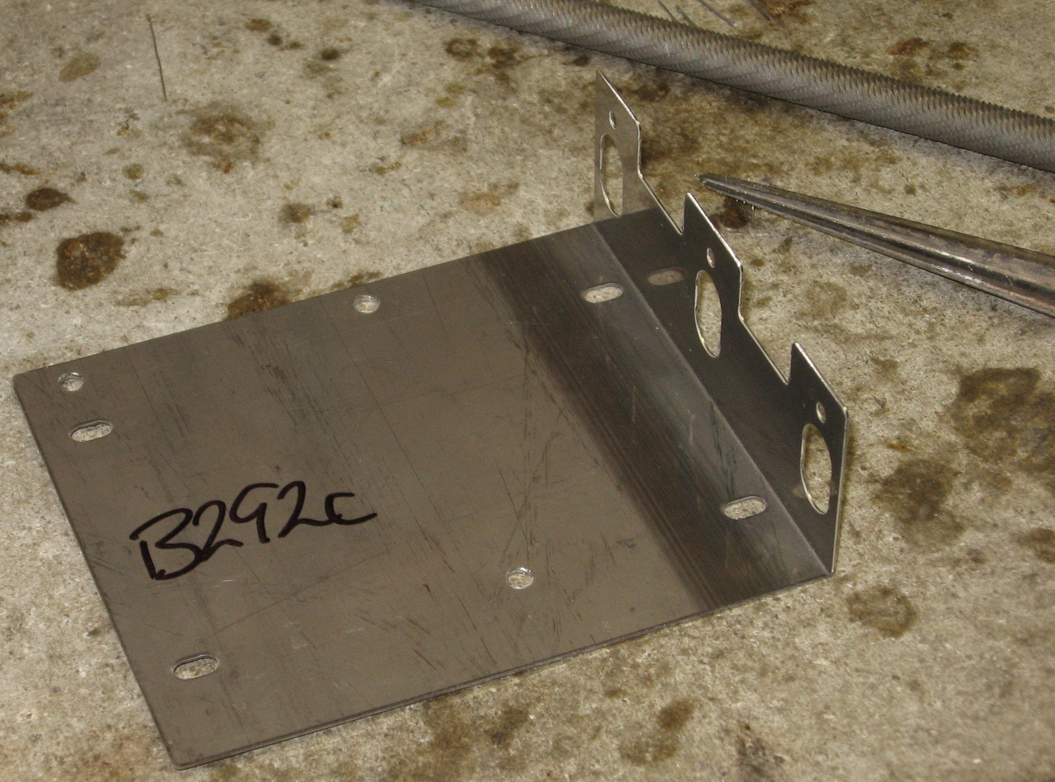
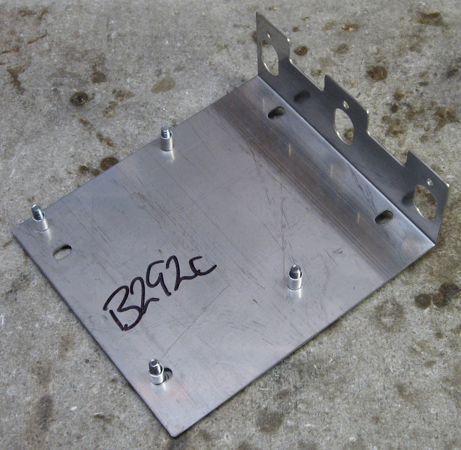
Will and I used the BOM provided by Thomas White. Mounting Bracket This was easy to prepare - just drilled the holes into a short, 3-pot bracket.
|
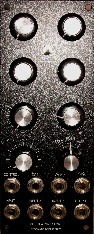
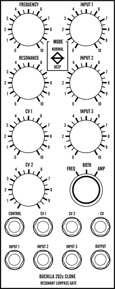
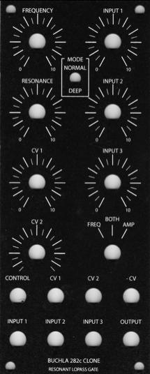
Panel |
|
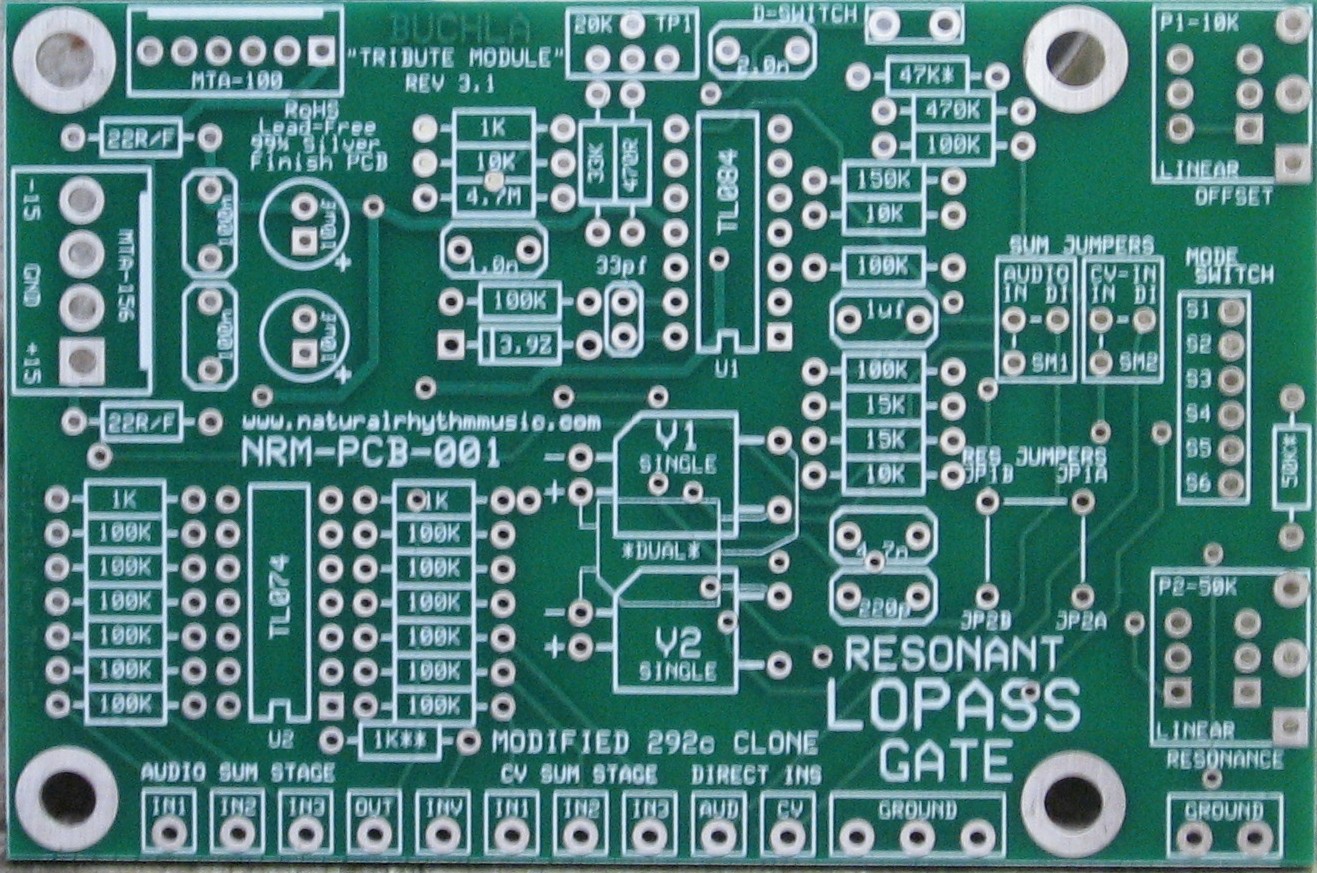
We got ours from Bridechamber:
|
Construction Phase 1All the stuff in Phase 1 gets soldered using "Organic" Solder. At every break in the action, we wash the board off to get rid of the flux.
|
|
Jumpers |
|
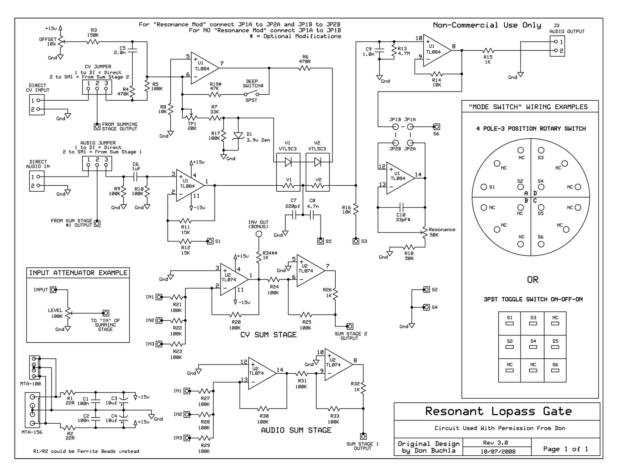
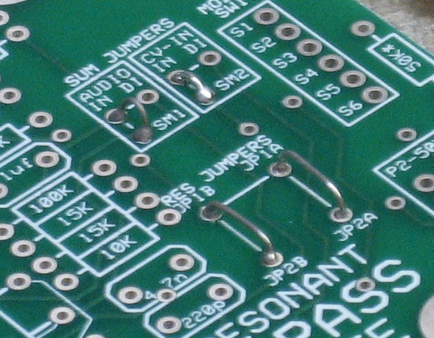
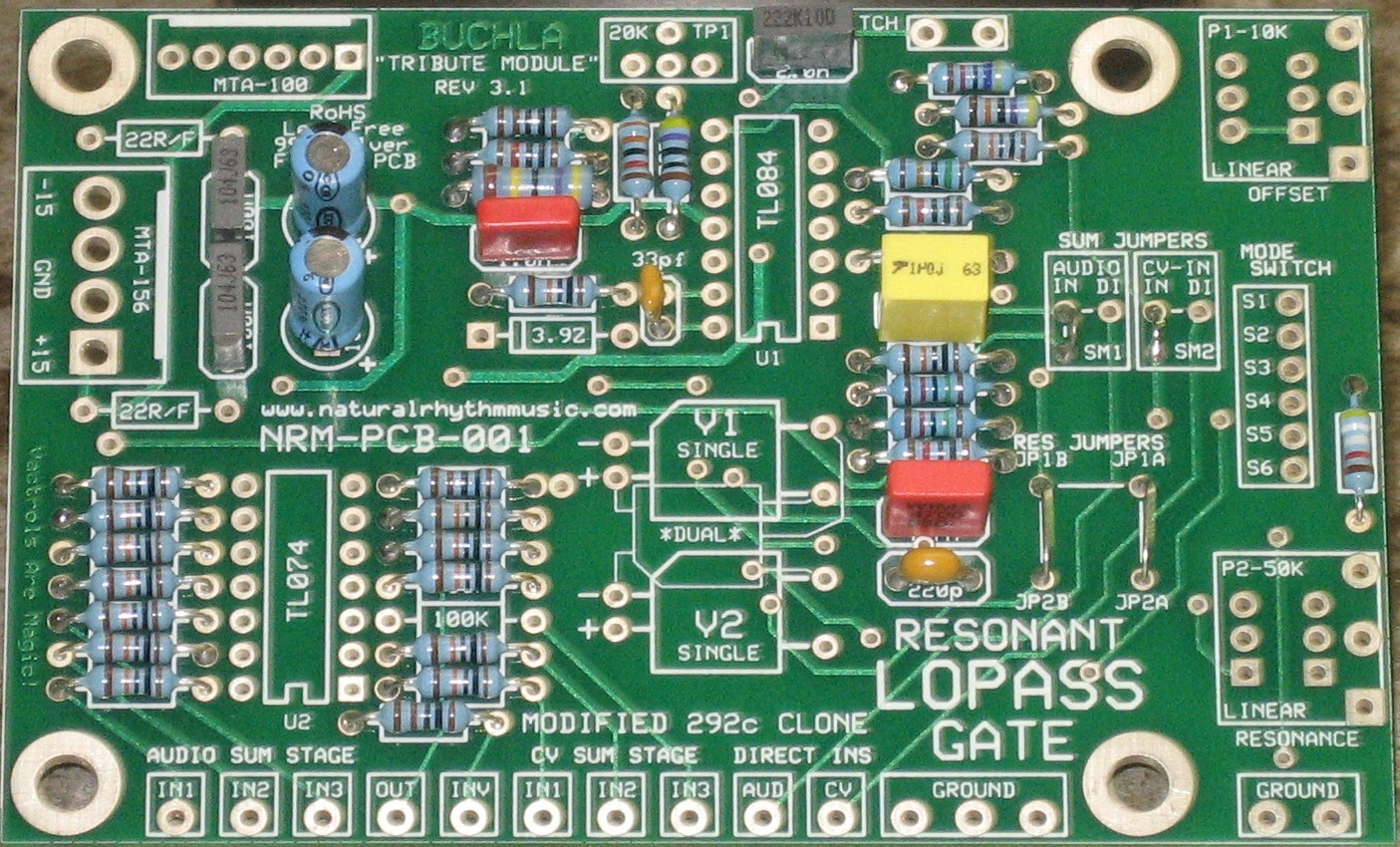
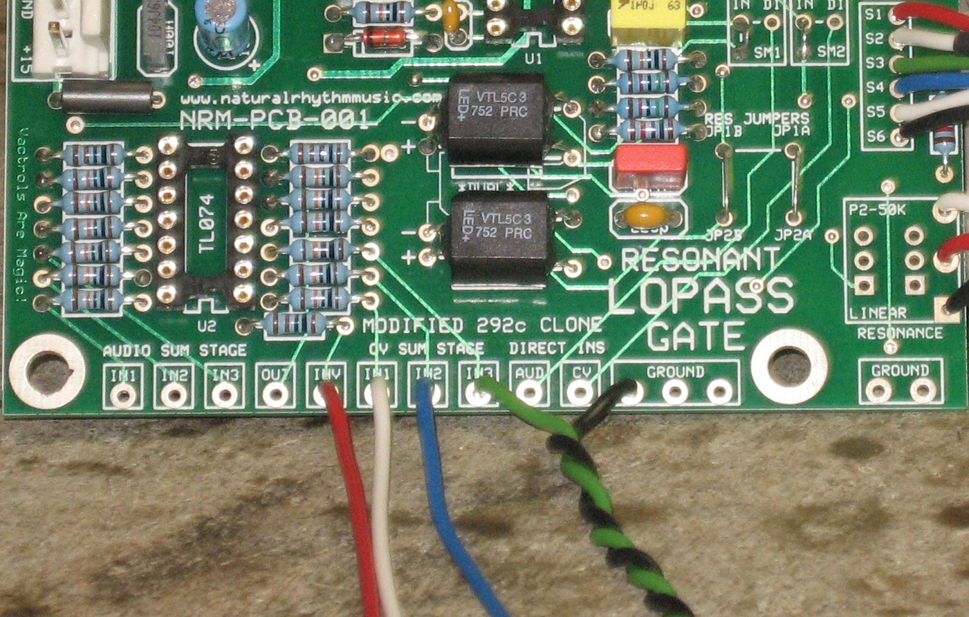
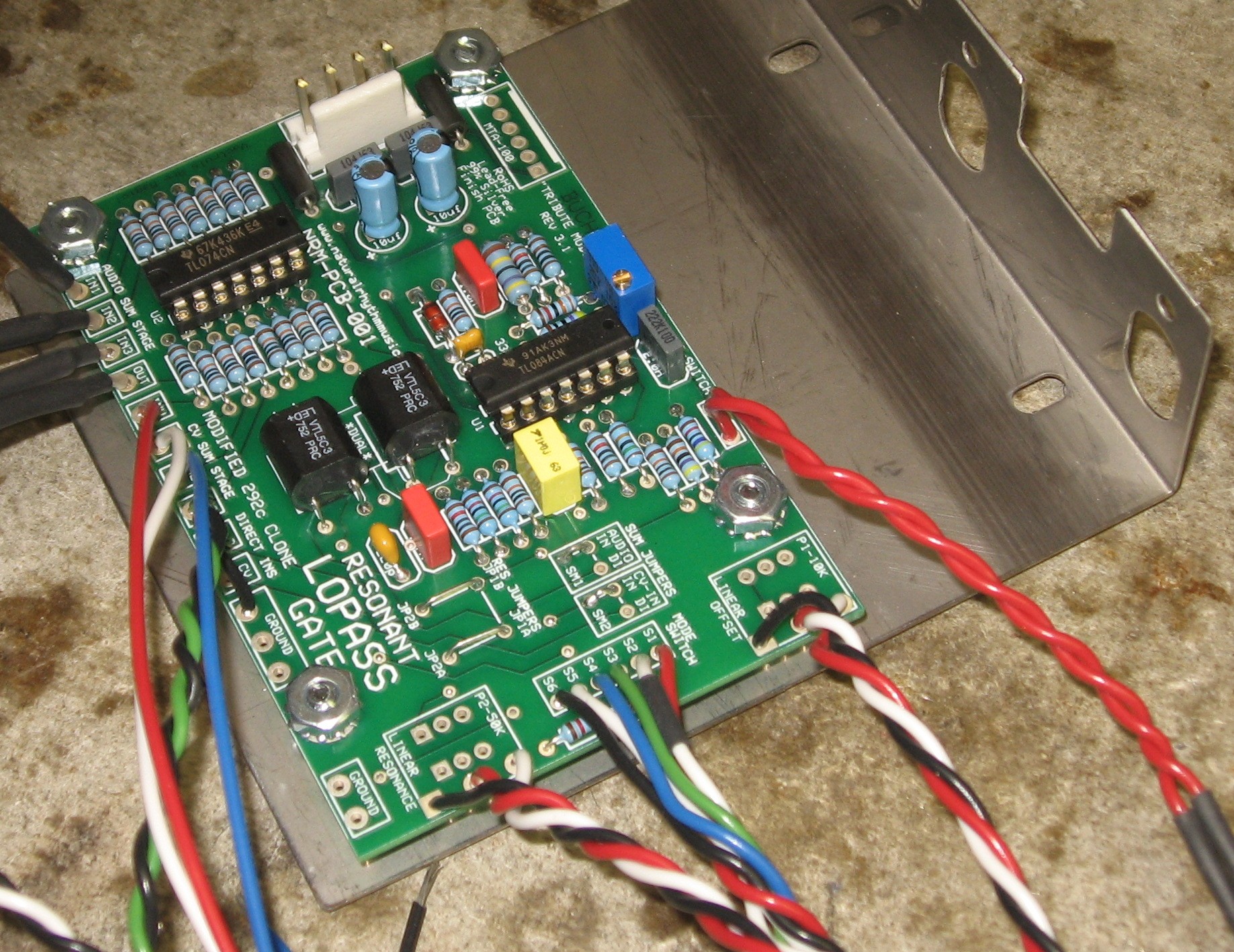
We want resonance and, because the Bridechamber panel has 3 audio inputs and 3 CV inputs, we'll want to use the little on-board summing features; hence the placement of these four jumpers:
|
|
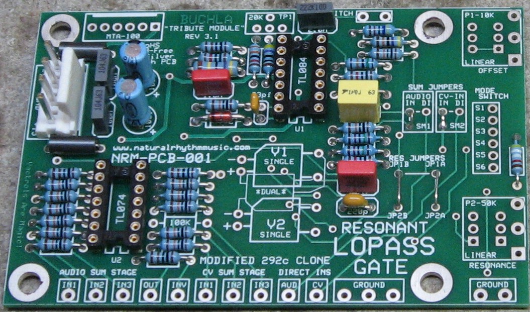
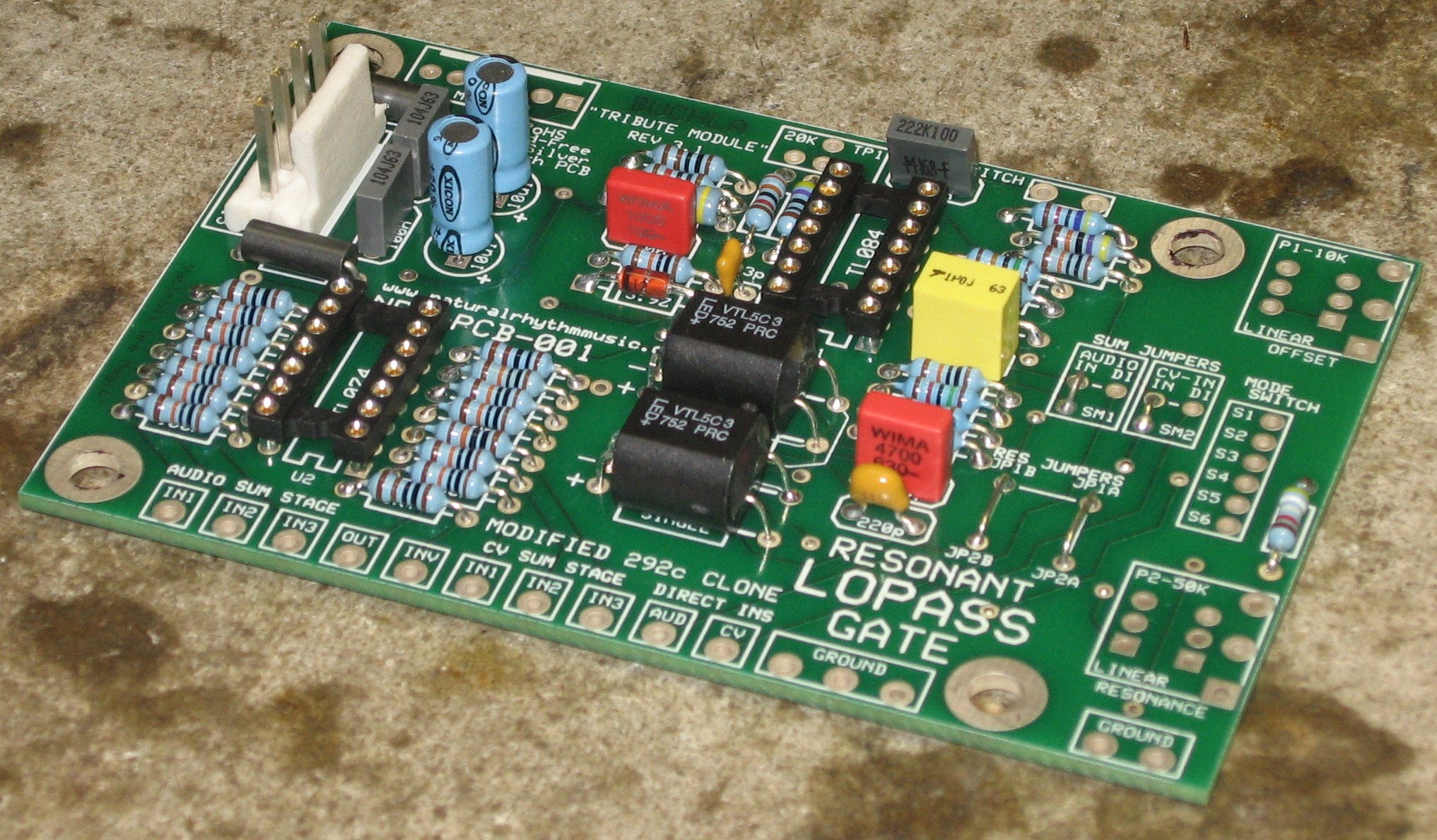
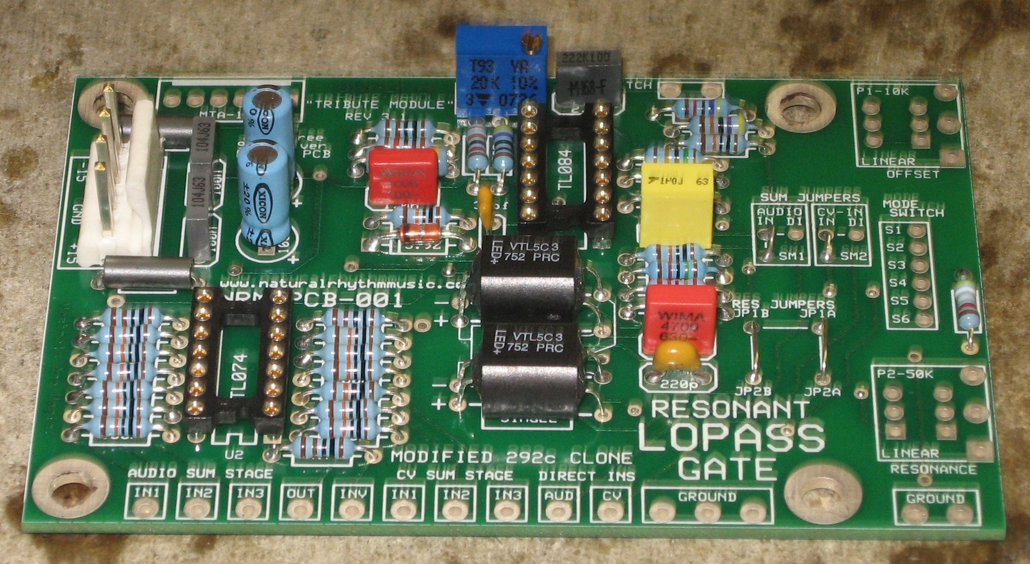
Resistors & Capacitors |
|
You can see we left one of the 100K resistors out - the one that's down near the TL074 IC. We thought we wouldn't need that one because it's for a third CV input and the panel only has CV1 and CV2 jacks and pots. Later on, we put it in too because we realized we'd need to use it for the "CONTROL" CV.
|
|
IC sockets, Diode, Power Stuff |
|
|
|
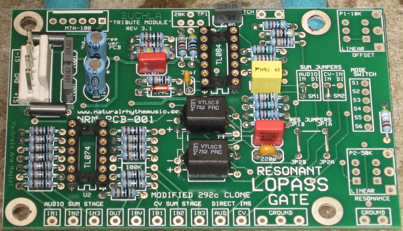
Vactrols |
|
|
|
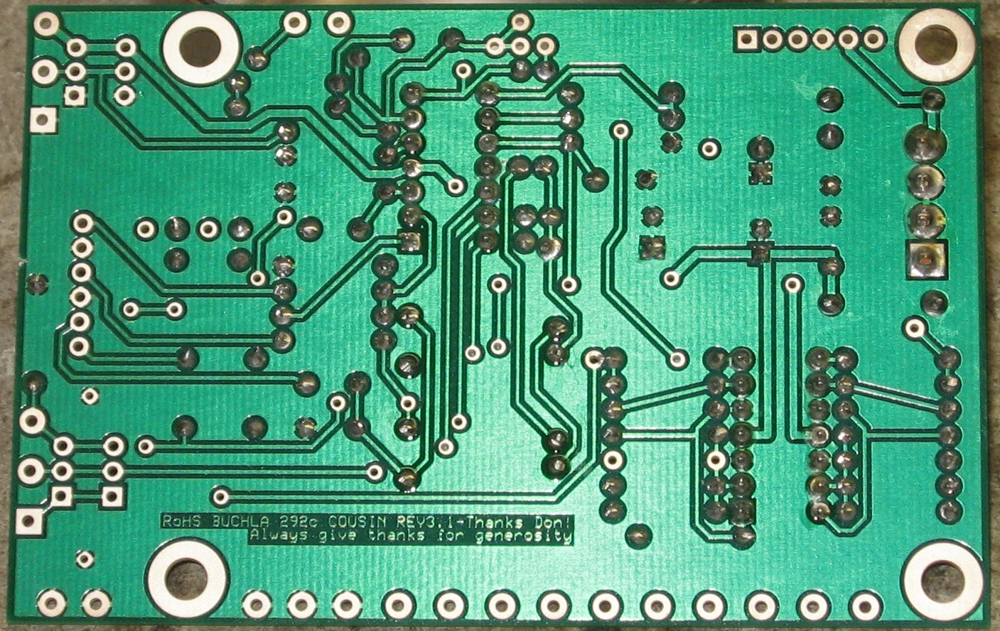
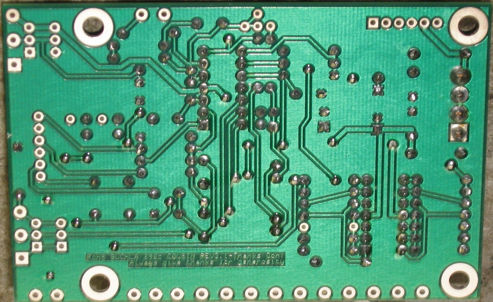
Via Holes |
|
|
|
The CONTROL CV resistor (CV3) |
|
|
|
|
Construction Phase 2All the stuff in Phase 2 gets soldered using "No Clean" Solder. |
|
The 20K trimmer |
|
|
|
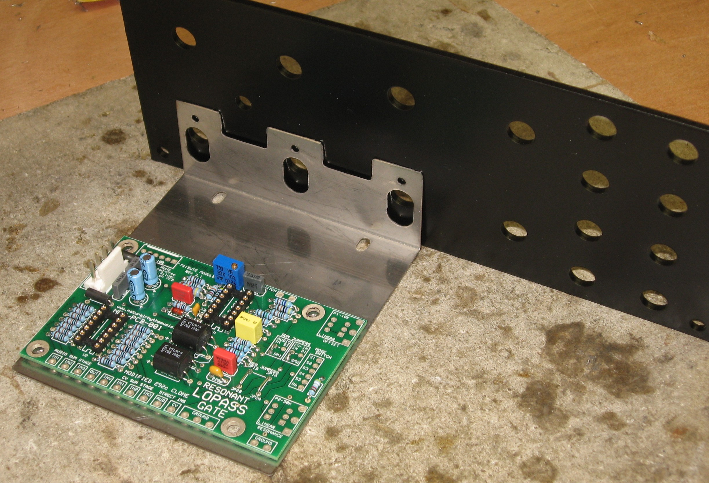
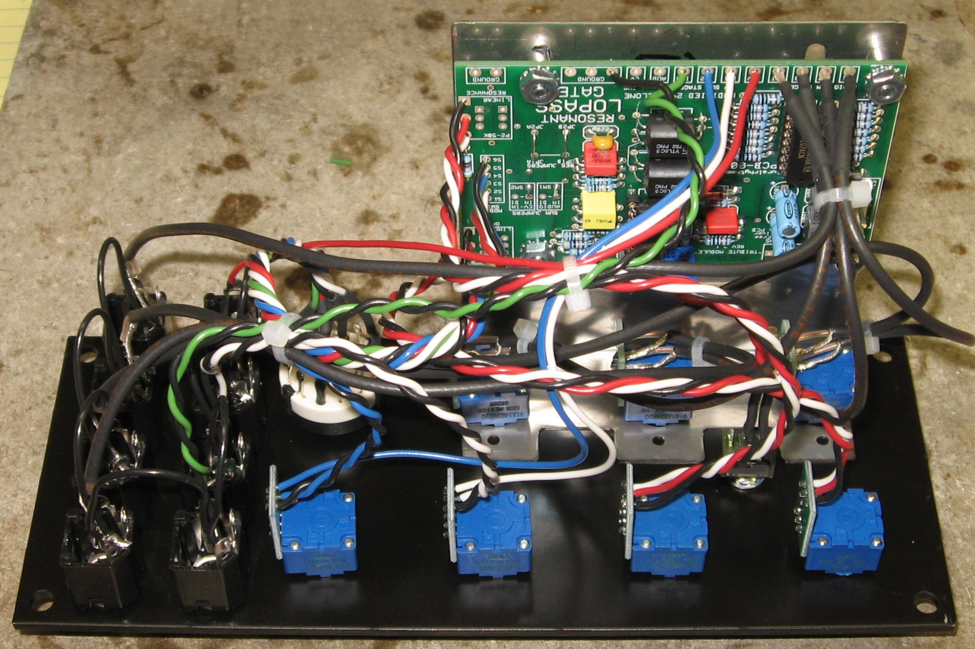
Wires |
|
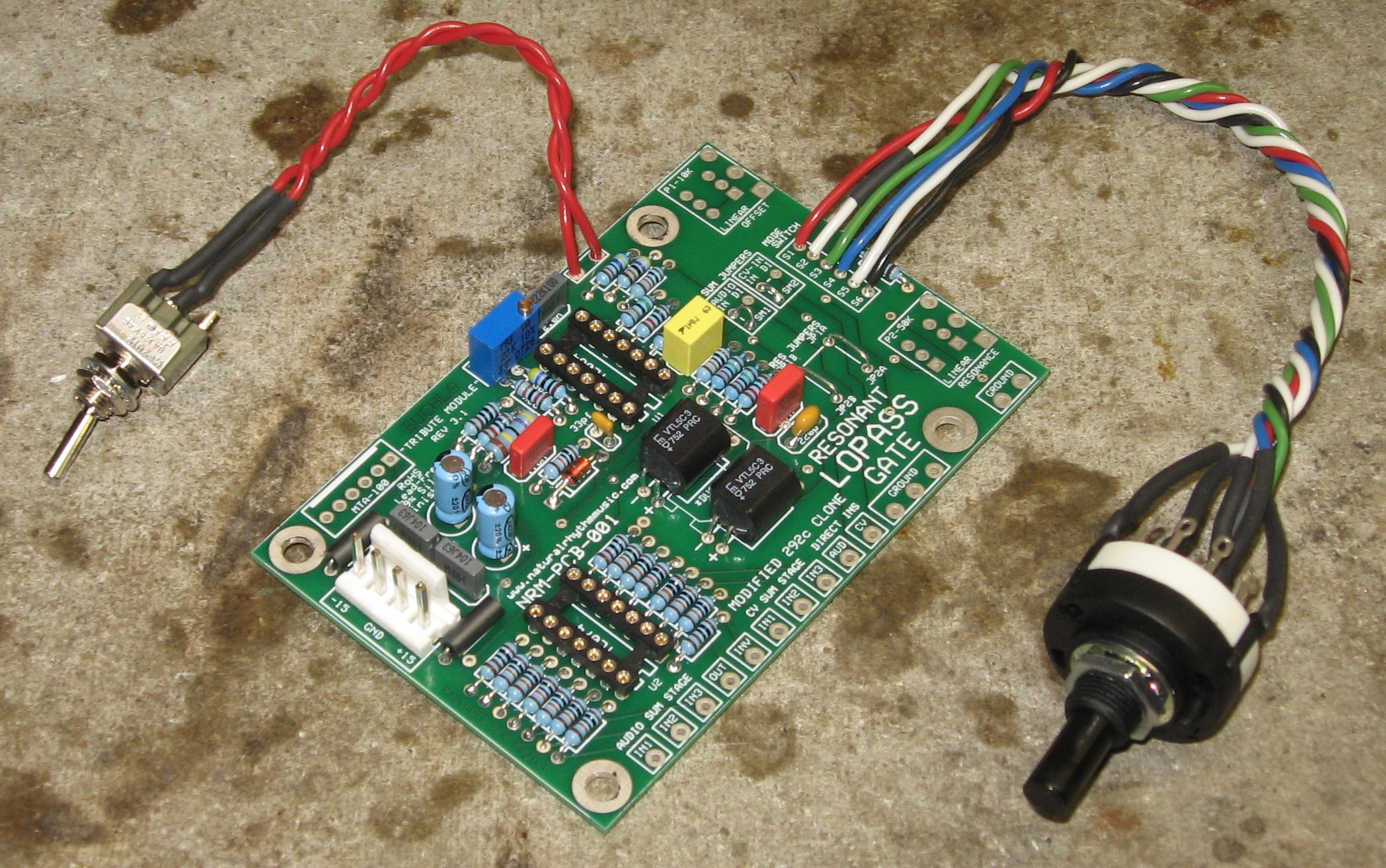
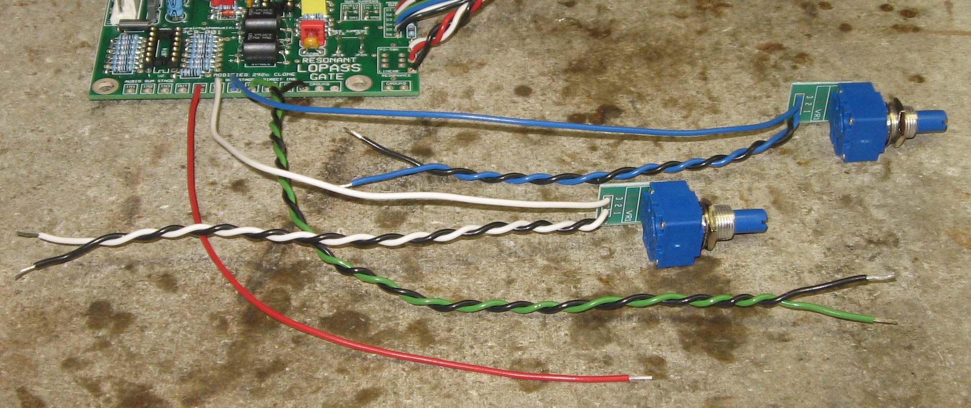
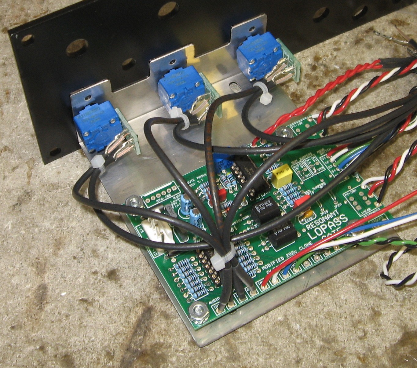
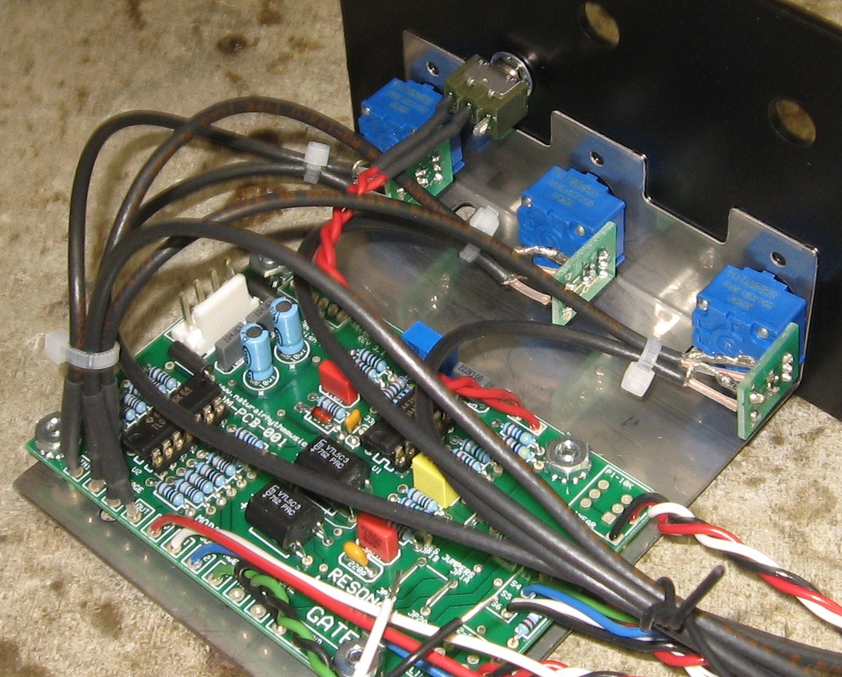
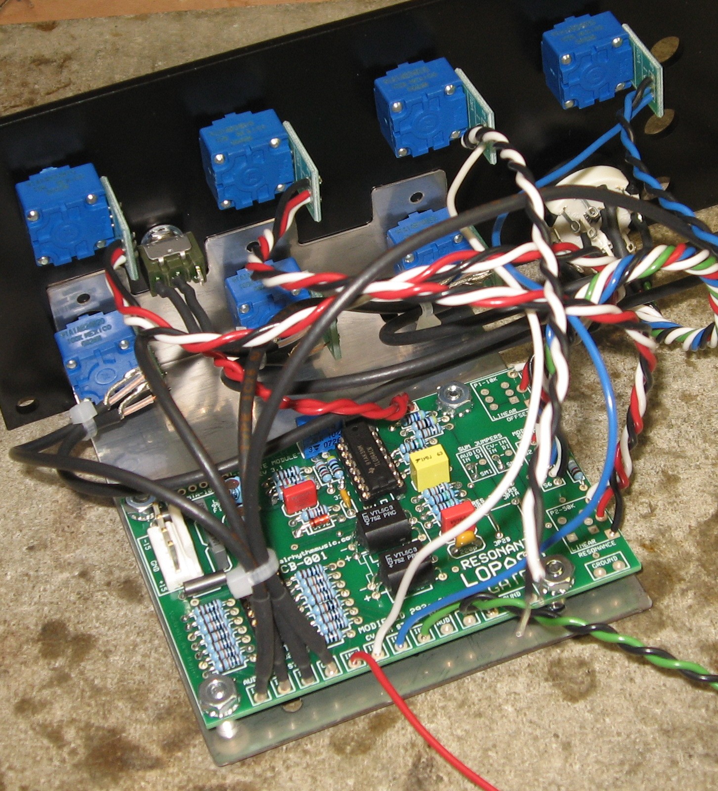
This required some consideration - so we set the PCB, bracket, and panel up like this to check things out:
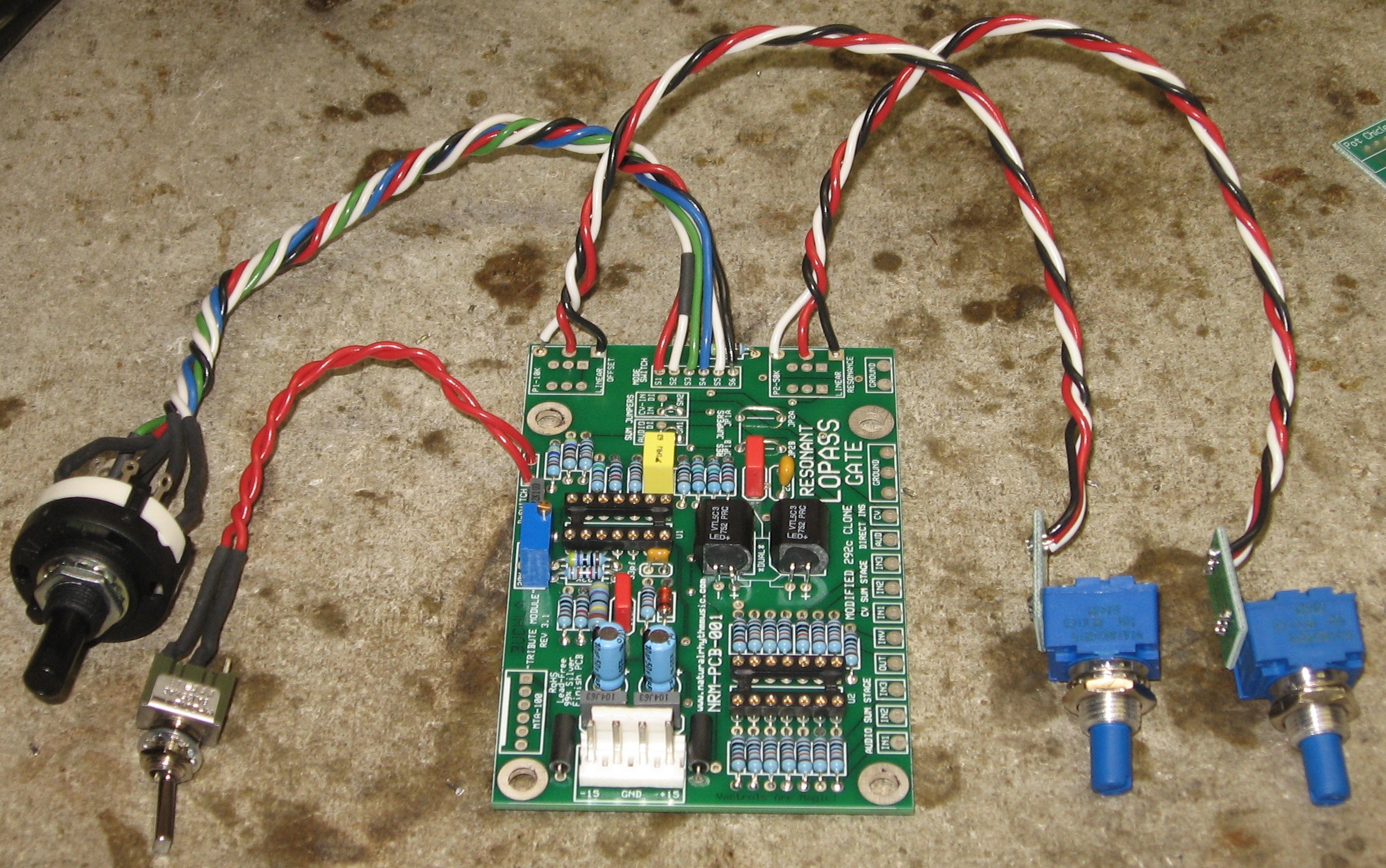
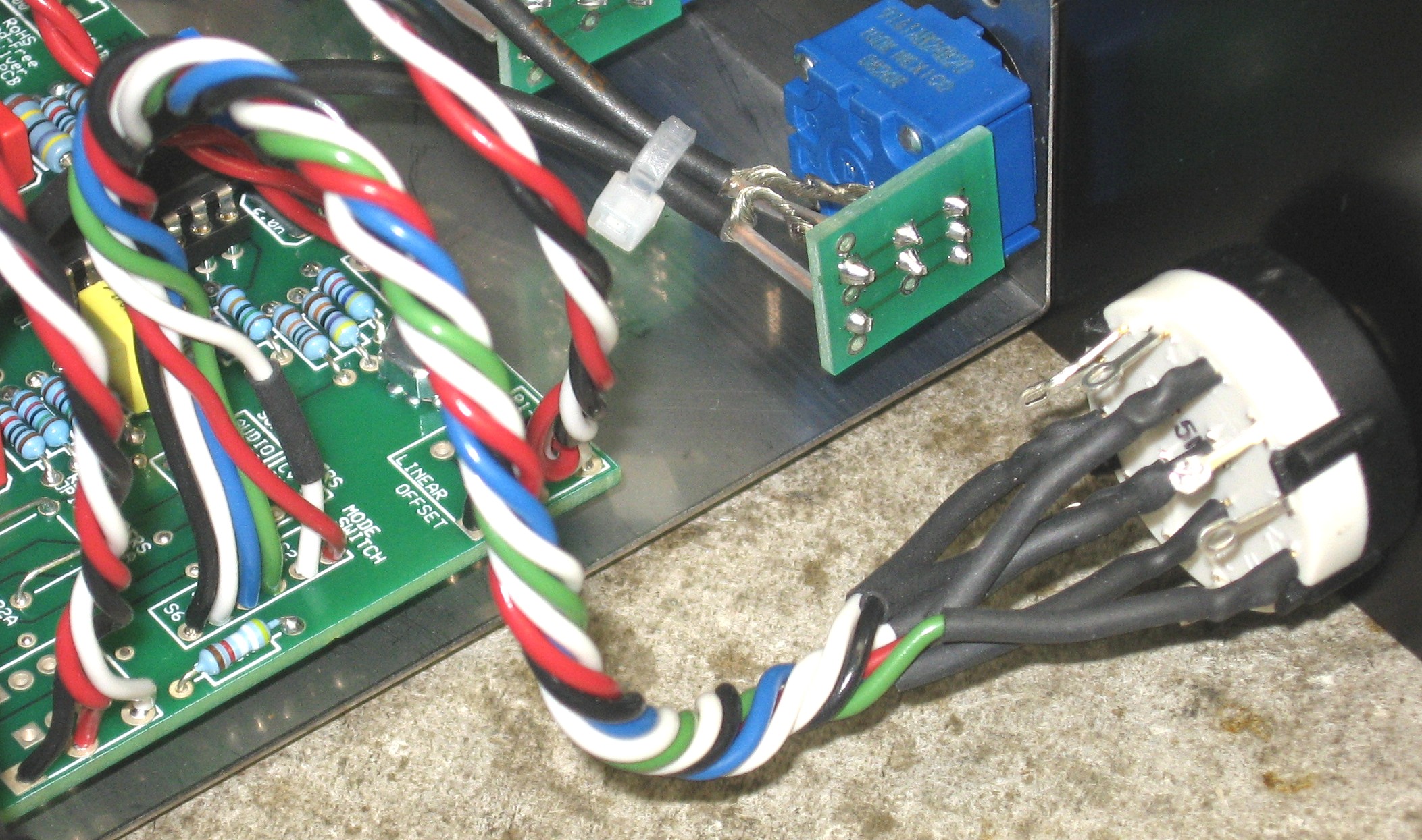
We wanted to mount the PCB on the right side (from the front) of the panel. So we decided not to solder the FREQUENCY and RESONANCE pots into the PCB, we wired them up instead. We figured out the lengths of wire to use: COAX - we used this for the Audio inputs and the Output. The PCB has just one pad/hole per connection so in all cases, we connected the shield to ground on the opposite end from the PCB. We grounded all the jacks with a separate wire:
IN1 (Audio) - PCB to INPUT 1 Pot: 6-1/2 in.; Pot to INPUT 1 Jack: 12 in. WIRE - here again, the PCB has just one pad per connection so the grounding came from the jacks. We used the CONTROL jack for that ground connection to the PCB:
-CV - (single) PCB to -CV Jack: 8 in. |
|
Switches |
|
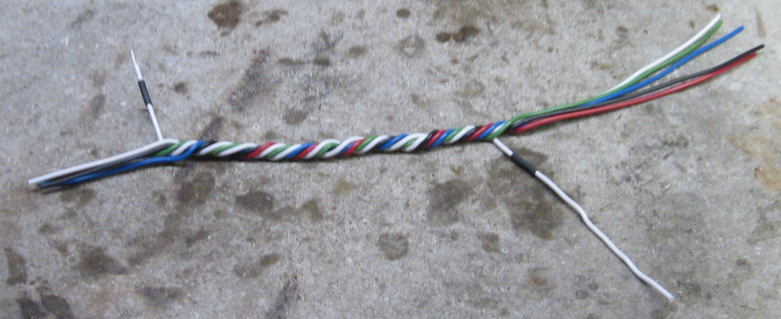
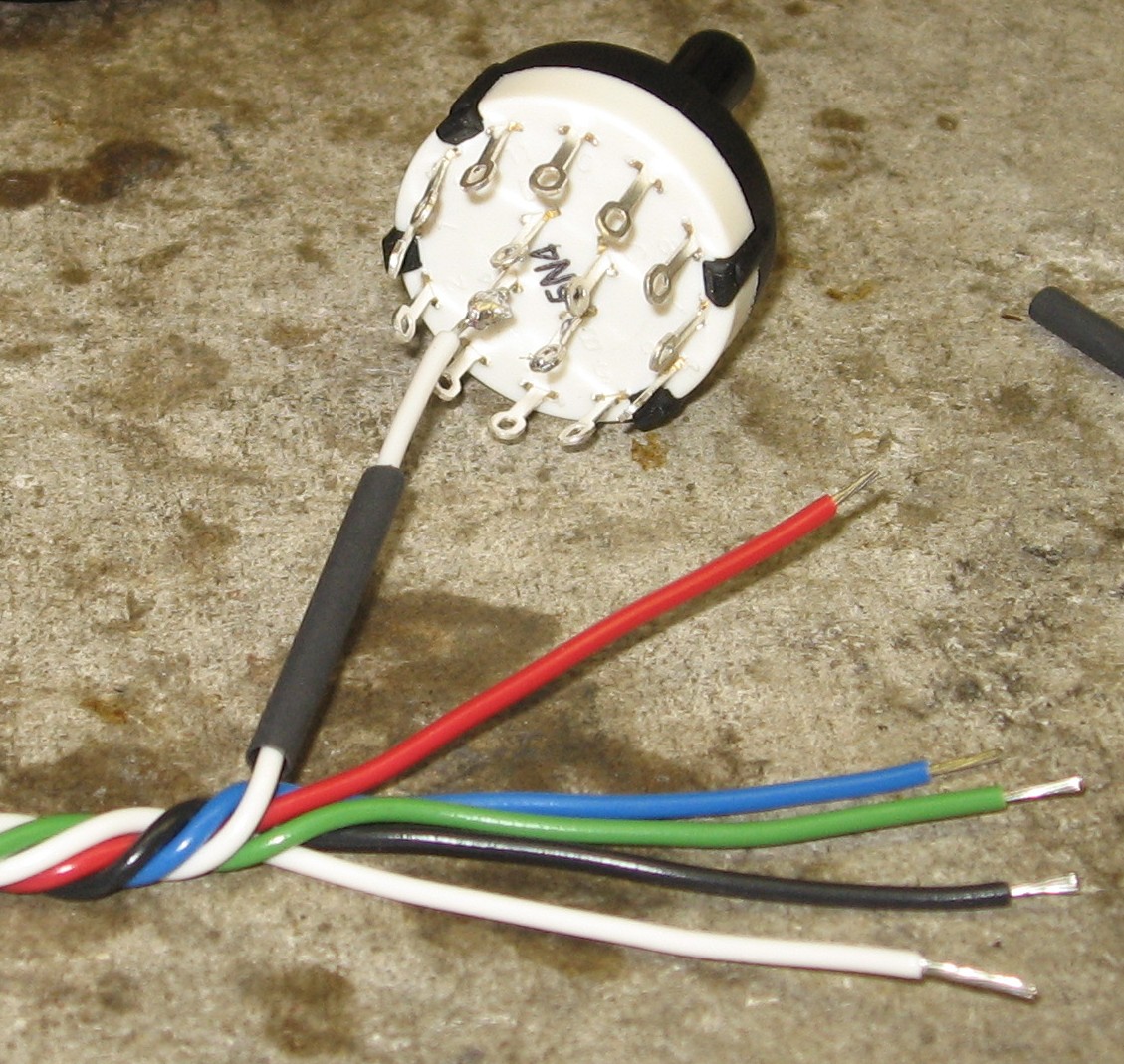
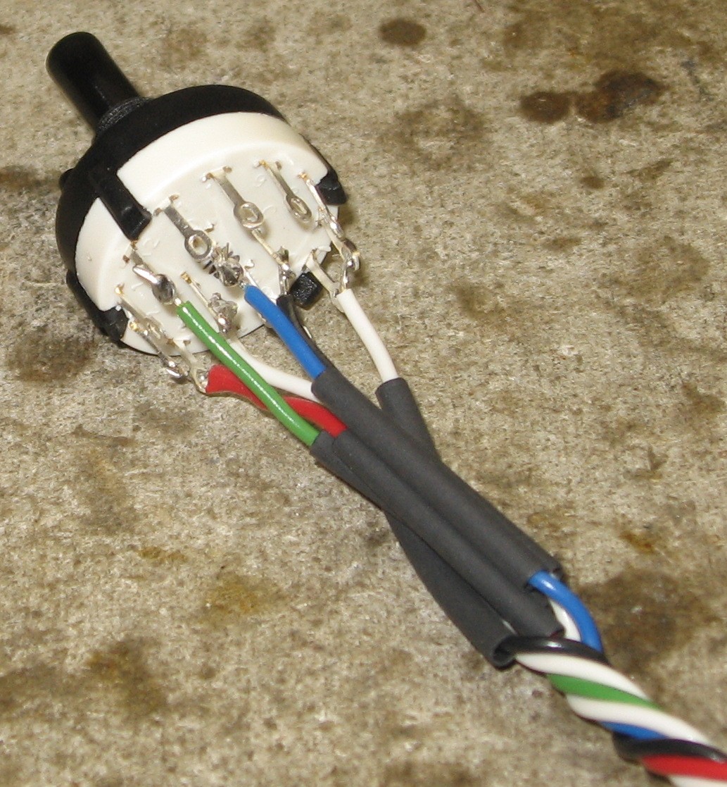
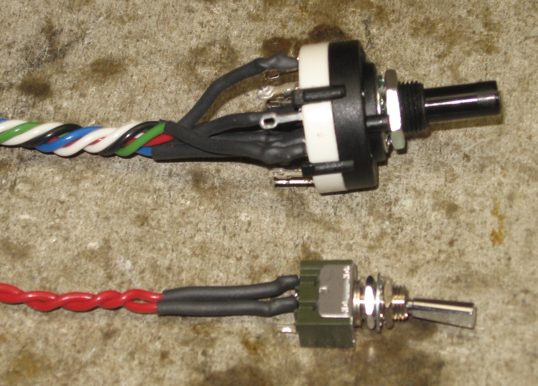
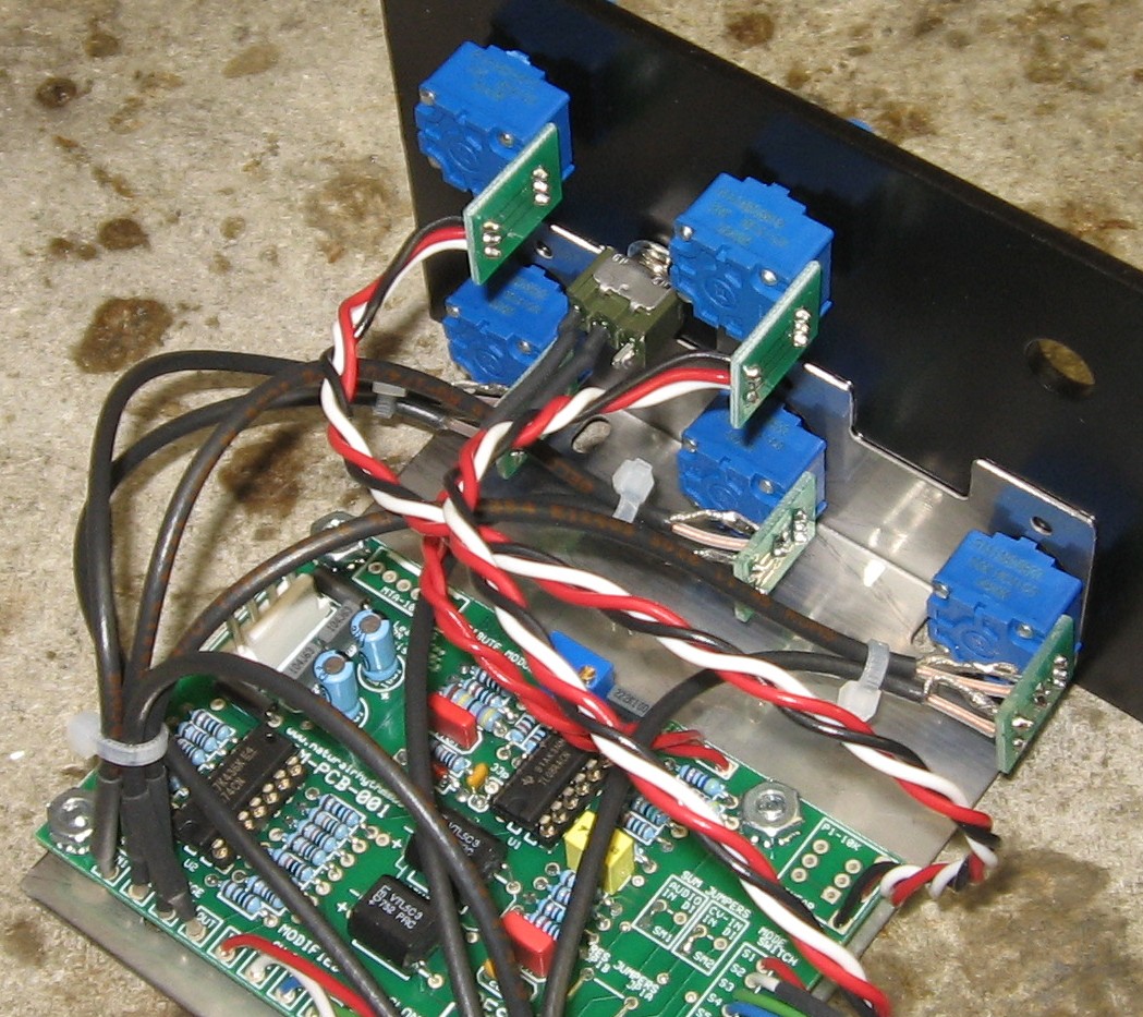
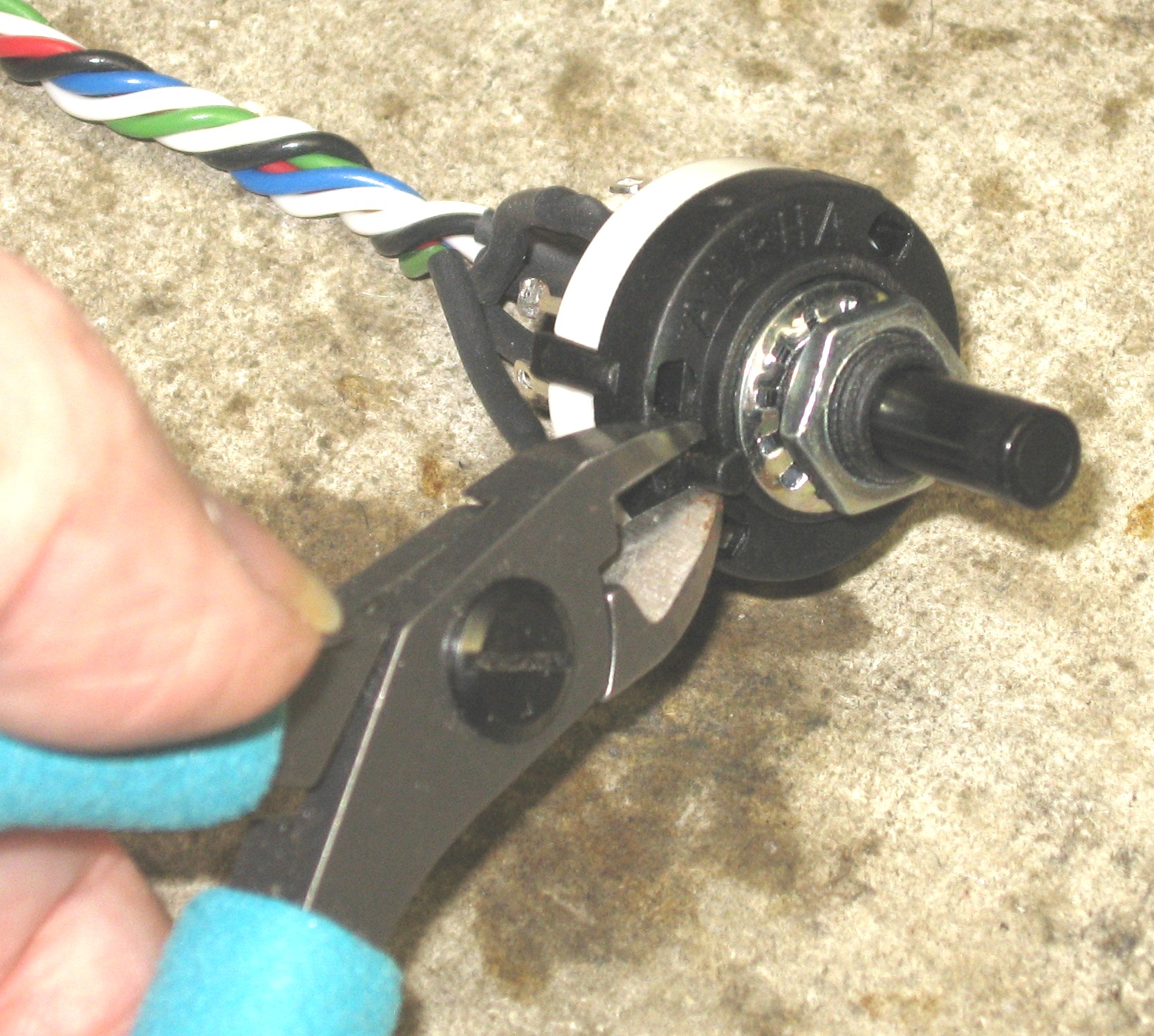
OK - so we started with the switches - the rotary switch and the SPDT "deep" switch. Rotary Switch - we needed six wires - we have five colors - so we marked one of the white ones with a bit of heat shrink. We later removed the heat-shrink from the switch-end 'cause we realized it would be in the way - but we immediately soldered that wire to the switch pad A. Here's how the wires worked out:
S1 - red - switch pad 3
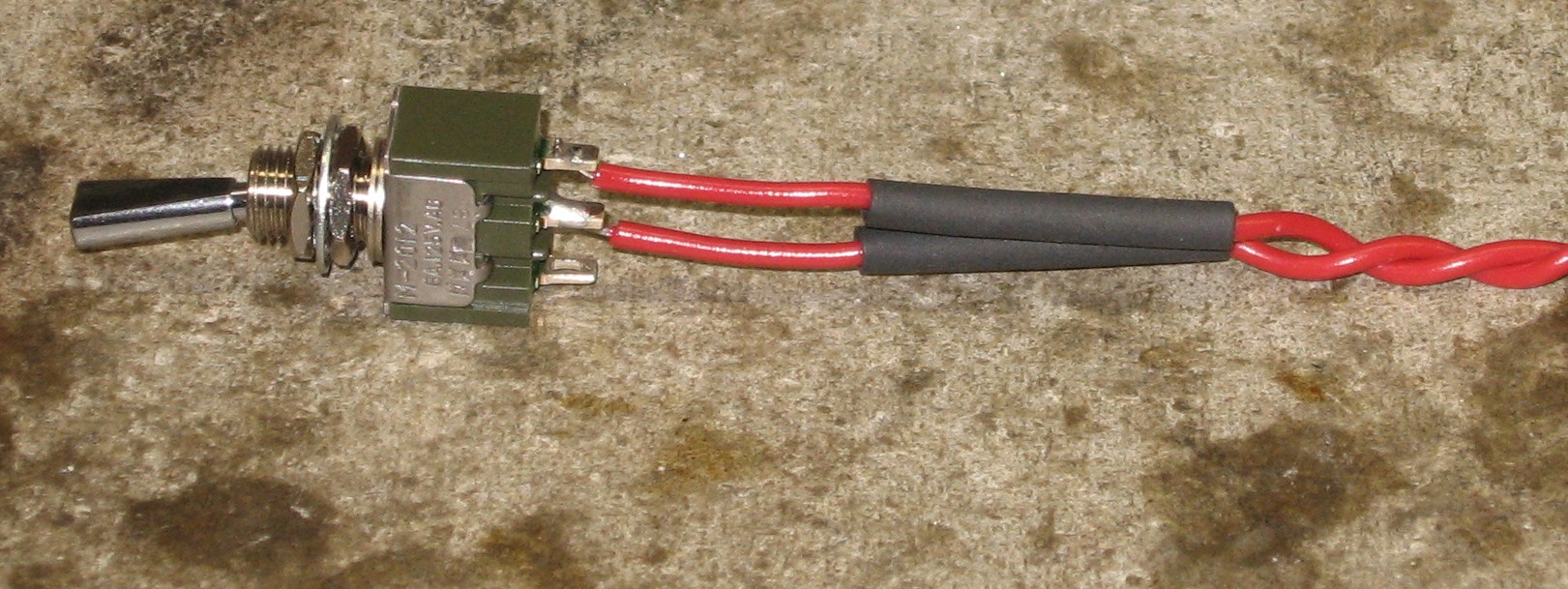
SPDT - We used two red wires - polarity doesn't matter here:
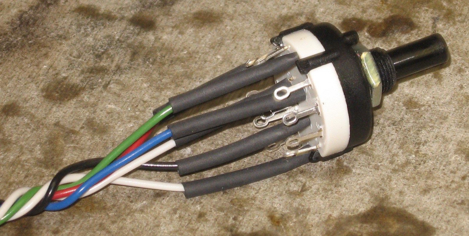
Heat Shrunk and Soldered:
|
|
Control Pots |
|
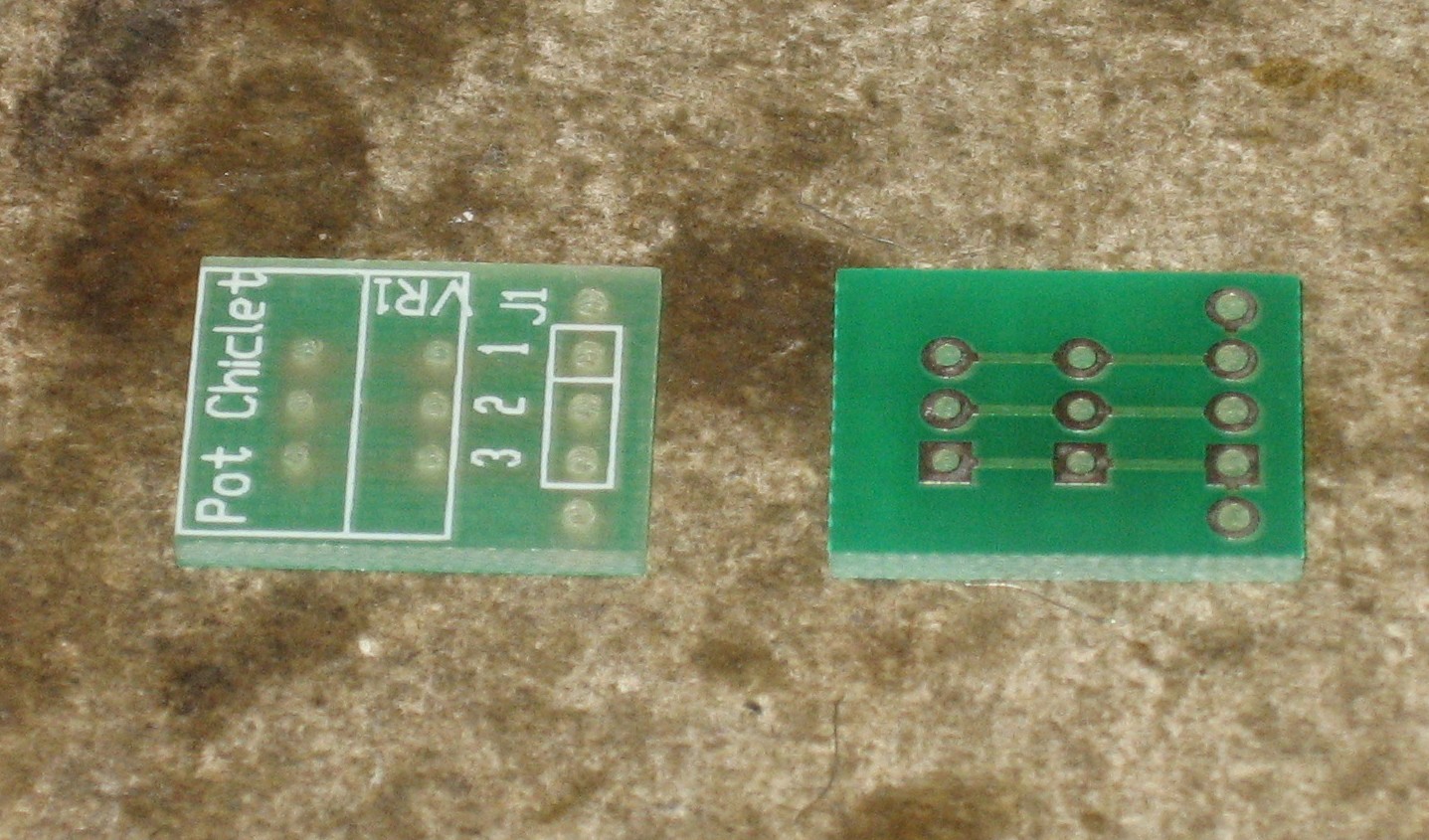
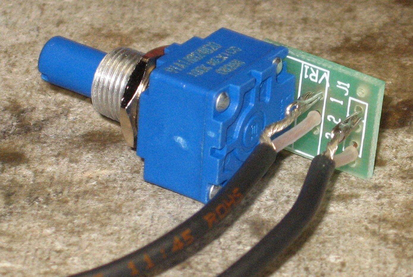
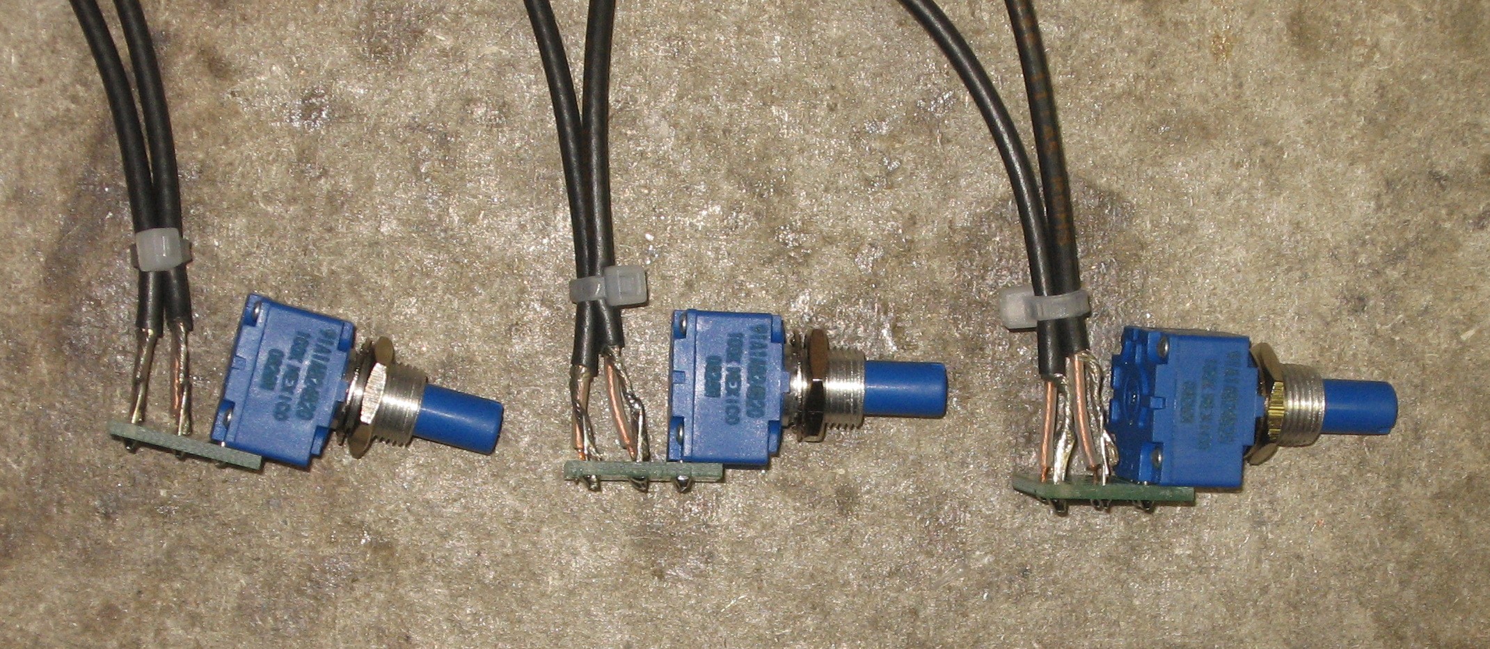
Next, we dealt with the FREQUENCY and RESONANCE pots. We used "chicklets," from Bridechamber, to make the connections.
|
|
CV inputs |
|
|
|
Output |
|
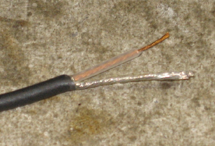
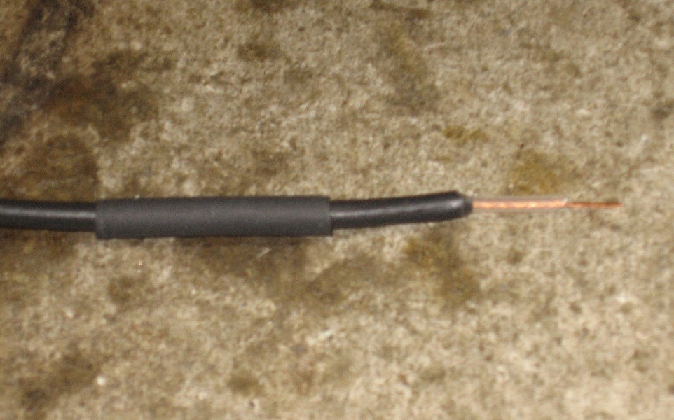
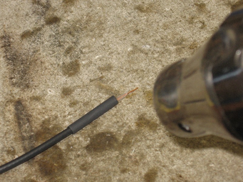
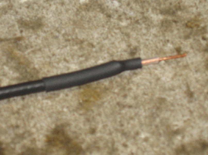
OK - so on the PCB side of the output and input, there's only the one pad for the signal. The ground connection needs to come separately. But we wanted to use coax for the audio ins and the output so we prepared those bits of coax to solder into the PCB like this:
The OUTPUT coax soldered in like this:
The ground (shield) is fed fron the jack-side of the coax. |
|
Audio inputs |
|
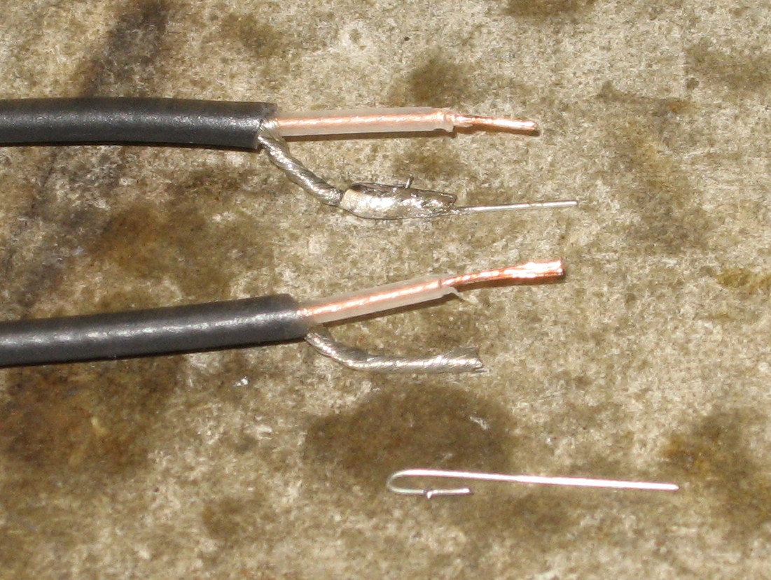
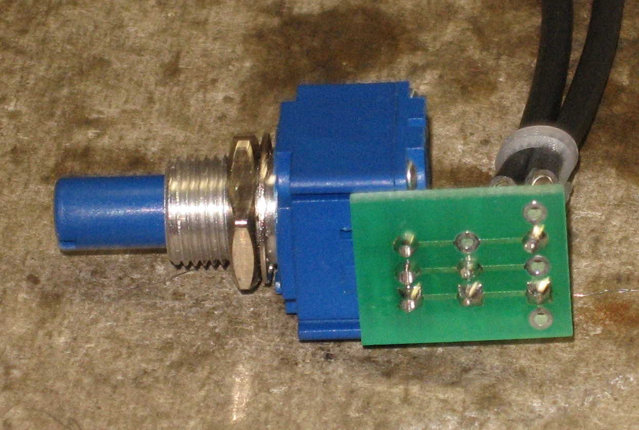
The audio inputs required two sections of coax; one from the PCB to the panel-mounted potentiometer, and one from that potentiometer to the jack. So the grounded coax shield connection needs to come through the potentiometer from the input jacks. Here's the neat way we dealt with this issue:
|
|
Mounting Bracket |
|
We stuck the ICs into their sockets and mounted the PCB:
|
|
Controls |
|
We started with the input pots - they hold the mounting bracket onto the panel.
|
|
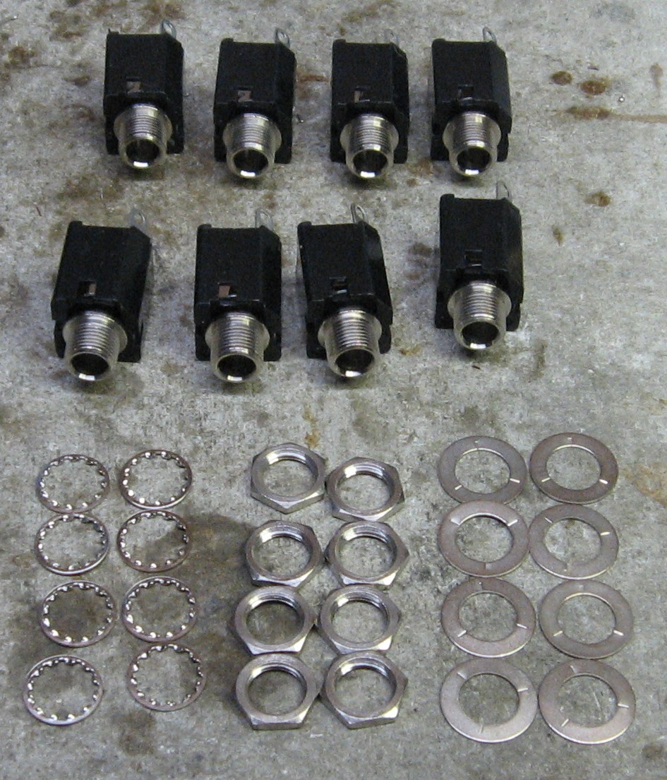
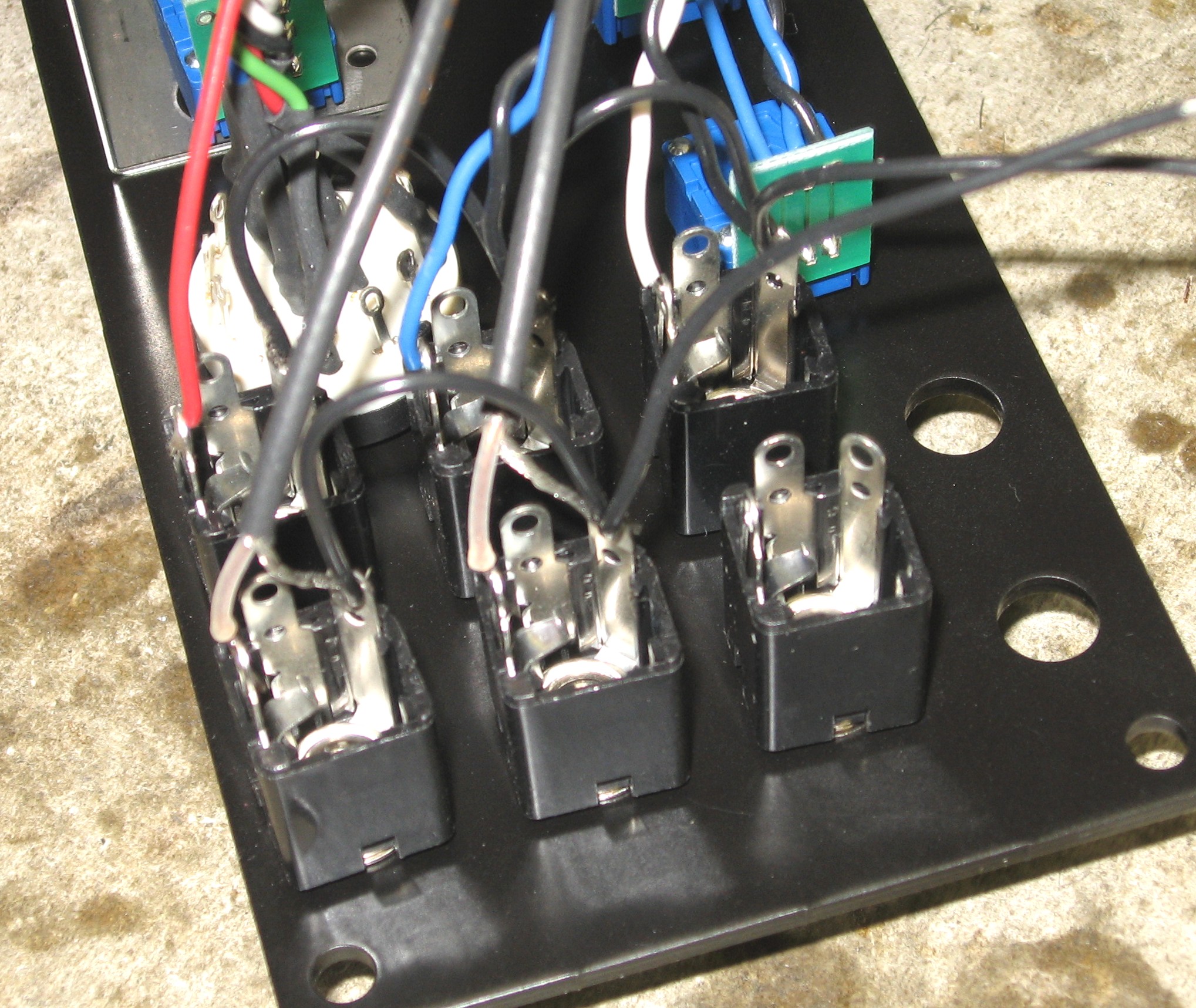
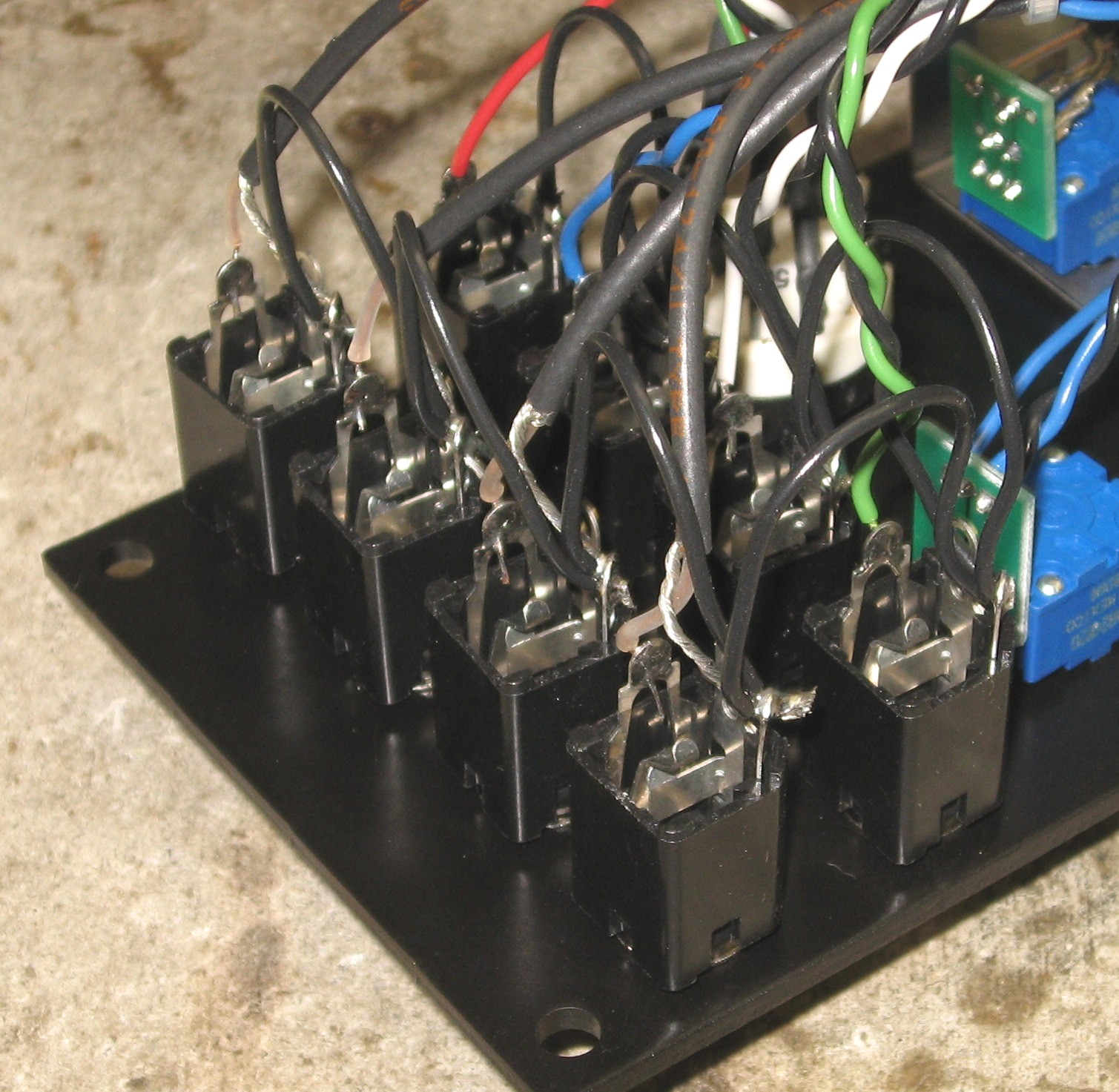
Jacks |
|
The ground will come from the CONTROL connection - so every jack's ground is linked together:
|
|
Connections Done |
|
|
Set up / Testing |
Use Notes |
|
|


|
The fine Print: Use this site at your own risk. We are self-proclaimed idiots and any use of this site and any materials presented herein should be taken with a grain of Kosher salt. If the info is useful - more's the better. Bill and Will © 2005-2011 all frilling rights reserved
|